An electrical enclosure outdoor selection starts with actual exposure, the NEMA or IP rating, material, and complete installed assembly, not a weatherproof label. Use Type 3R for falling rain where other hazards are absent, Type 4 for hose exposure, and Type 4X when corrosion resistance is also needed.
You may be replacing a disconnect with water tracks inside the door, or reviewing a submittal that names the cabinet but leaves every hub and accessory to the installer. The immediate problem isn't finding another box. It's identifying what the existing specification missed before you buy the same failure in a different finish.
A rooftop junction cabinet mounted tight to a masonry parapet can look acceptable until the cover comes off. The gasket may be intact while corrosion rings the mounting bolts, a field-made top entry leaves a water path above the terminals, and moisture marks the back panel. The nameplate only describes the enclosure; outdoor suitability depends on the complete installed assembly.
Start with the condition of the equipment, using appropriate electrical safe-work procedures before opening or inspecting it. Look for trails below hubs, corrosion around mounting bolts, damaged paint at field cuts, and uneven gasket compression. Those details distinguish water entering through an opening from moisture forming inside. They also show whether the problem began with the enclosure rating, the mounting arrangement, or an accessory.
The installation is part of the requirement
OSHA's general industry electrical rule requires cabinets, cutout boxes, fittings, boxes, and panelboard enclosures in damp or wet locations to prevent moisture or water from entering and accumulating; in wet locations, those enclosures must be weatherproof. 29 CFR 1910.305 also requires at least 6.35 mm, or 0.25 inch, of airspace between the enclosure and its supporting surface, with an exception allowing nonmetallic enclosures directly against concrete, masonry, or tile.
That makes a tighter seal an incomplete answer by itself. A sealed cabinet can trap condensation, while an unrated field penetration, wrong hub, or improper mounting arrangement can void the rating. Select the enclosure type from the dominant site exposure, then verify that the installed assembly preserves it.
Weatherproof means constructed or protected so weather exposure doesn't interfere with successful operation. Rainproof, raintight, or watertight construction can satisfy that purpose when additional conditions such as snow, ice, dust, or temperature extremes aren't factors. A rain-shedding cabinet beside a chemical exhaust isn't automatically suitable just because rain stays out.
Practical rule: Investigate where water travels, not just where it finally collects.
Turn the location into a specification
Before selecting a replacement, record the conditions that the purchase document needs to address:
Water exposure: Falling rain, wind-driven rain, splash, hose cleaning, or potential inundation.
Atmosphere: Salt, process chemicals, airborne dust, and nearby exhaust.
Support conditions: Wall construction, mounting arrangement, drainage, and service access.
Operating conditions: Internal heat, temperature swings, door-opening frequency, and security.
Use the dominant exposure to choose the enclosure type. Use the remaining conditions to test whether the material, finish, fasteners, drainage, and accessories suit the site. Hose cleaning, for example, presents a different water path than falling rain, while salt or process chemicals make construction materials part of the decision.
Confirm the enclosure type against the NEC edition adopted in the project jurisdiction and applicable local amendments before finalizing the drawing. OSHA requirements don't replace that project-specific code review, manufacturer instructions, or engineering judgment.
The useful procurement description reads like an installed condition. It states the environmental exposure, mounting conditions, required construction, and field penetrations or accessories the supplier must evaluate as one assembly.
NEMA Types for Outdoor Exposure
Outdoor NEMA types by exposure
Type
Dust
Water
Ice
Corrosion
Typical use
3
Windblown dust
Rain and sleet
External ice
No added corrosion designation
Dusty outdoor equipment
3R
Not dust-tight
Falling rain, sleet, and snow
External ice
No added corrosion designation
General outdoor gear, often with a drain
3S
Windblown dust
Rain and sleet
Must operate when ice-laden
No added corrosion designation
Mechanisms that must work under ice
3X, 3RX, 3SX
Same as the base type
Same as the base type
Same as the base type
Yes
Corrosive-area versions of the base types
4
Windblown dust
Rain, sleet, snow, splashing, and hose-directed water
External ice
No added corrosion designation
Washdown and hose exposure
4X
Windblown dust
Same water protection as Type 4
External ice
Yes
Coastal, chemical, salt, and wastewater
6
Dust protection specified by the type
Hose-directed water and temporary submersion
External ice
No added corrosion designation
Brief submersion at limited depth
6P
Dust protection specified by the type
Hose-directed water and prolonged submersion
External ice
Yes
Prolonged submersion under specified conditions
Choose the row from site evidence, not the type used on the previous project. This is a selection aid, not a substitute for ANSI/NEMA requirements or the manufacturer's listing, including any applicable submersion conditions.
The Nidec enclosure guide distinguishes Type 3 protection against windblown dust and weather from Type 3R rain protection, and identifies the additional hose-water and corrosion protection associated with Types 4 and 4X. Those differences should drive the specification before price or appearance narrows the product list.
Falling rain isn't washdown
A sheltered exterior wall may justify Type 3R when the actual exposure is falling precipitation. Many such designs shed and drain water rather than seal every seam. Don't caulk a drainage path closed because it looks like an unfinished joint.
Use NEMA 3R junction boxes as candidates for that exposure, then review entry locations and mounting instructions for the particular product. A suitable cabinet can still be the wrong choice beside a dusty transfer point or within reach of a sanitation hose.
Type 3 addresses windblown dust as well as weather. Type 3S adds an important operational distinction: external mechanisms must remain operable when ice-laden. Protecting equipment against damage from external ice formation isn't the same thing as being able to operate a handle through that ice.
Hose water and corrosion change the purchase
Type 4 is the practical step up when splashing or hose-directed water is credible. Type 4X adds corrosion resistance, making it a stronger starting point for wastewater, coastal, chemical-processing, and deicing-salt exposure. Neither designation identifies the exact alloy, coating, or resin you should buy.
Submersion needs a different review. Types 6 and 6P address temporary and prolonged submersion respectively under specified conditions, but they aren't unrestricted flood-service claims. Obtain the manufacturer's applicable limits rather than treating submersible as permission for any depth or duration.
The Electrical Contractor discussion of ANSI/NEMA 250 identifies its scope as enclosures for equipment rated up to 1,000 volts in nonhazardous locations and notes that the 2020 edition superseded the 2018 edition. A copied drawing note therefore deserves an edition check, not automatic reuse.
Buy the environmental performance of the finished enclosure, not the promise of an empty shell.
Require the rating to cover the door, gasket, hubs, and installed accessories. An unrated window or an unapproved knockout modification can invalidate the claimed protection, even if the original nameplate remains attached.
None of these types is, by itself, a flood-depth, wildfire, or ultraviolet-resistance specification. Keep those site hazards explicit rather than trying to hide them inside a higher type number.
How IP Ratings Differ from NEMA Types
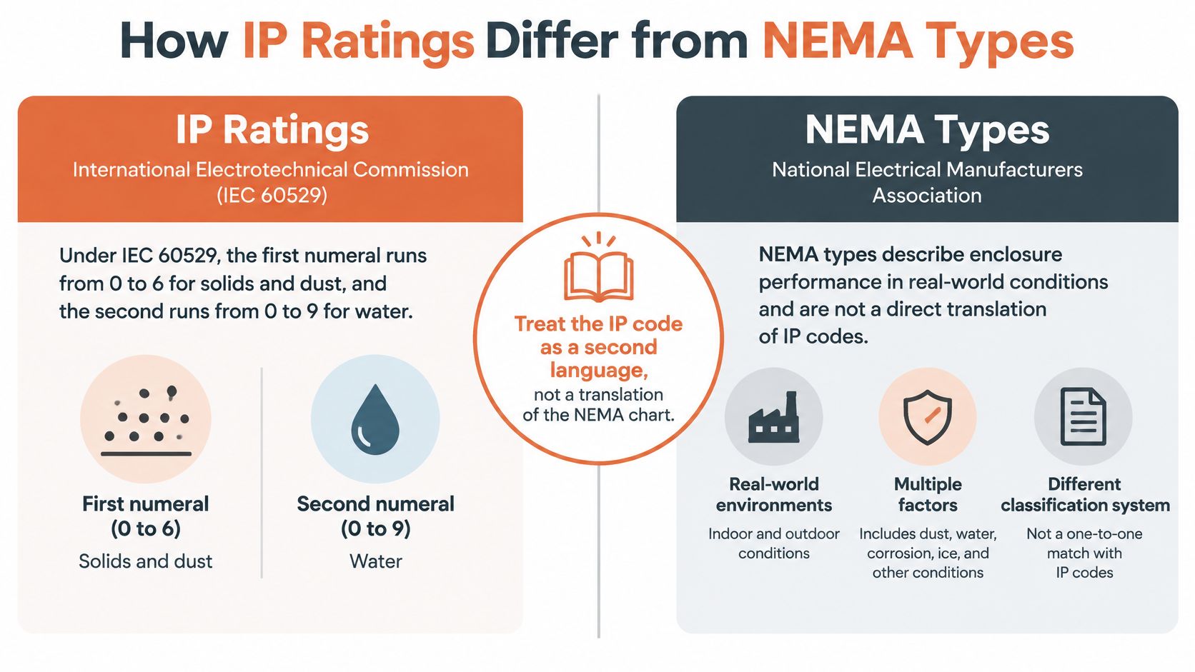
Treat an IP code as another protection language, not a direct translation of a NEMA type. It describes ingress performance through defined tests, but it doesn't answer every environmental question a North American enclosure specification may need to address.
The IEC explanation of IP ratings identifies a first numeral from 0 to 6 for solid objects and dust and a second from 0 to 9 for liquids; IEC 60529 applies to enclosures for equipment rated up to 72.5 kV. An X means the protection characteristic isn't specified by that position, so don't read it as either zero protection or a passed test.
Read each protection claim separately
IP codes often cited for outdoor equipment
Code
Solids
Water
What it does not prove
IP54
Dust protected
Splashing water from any direction
Not dust-tight and not a hose test
IP55
Dust protected
Water jets
Not a Type 4 conversion and not corrosion performance
IP65
Dust-tight
Water jets
Not high-pressure or immersion performance
IP66
Dust-tight
Powerful water jets
Not immersion, ice, or corrosion performance
IP67
Dust-tight
Temporary immersion under specified test conditions
Not a hose-down substitute and not corrosion performance
IPX9
Not specified
High-pressure, high-temperature spray
Says nothing about dust or ordinary-rain performance as a separate test
The digits don't create a universal ladder where every larger water digit automatically includes every lower water test. Temporary immersion and powerful jets impose different conditions on joints and seals. If equipment will experience both, obtain documentation that addresses both instead of choosing whichever code looks higher.
Likewise, high-pressure, high-temperature spray performance isn't a general endorsement for every cleaning chemical, nozzle practice, or cleaning temperature used at a plant. The enclosure's materials and the manufacturer's application limits remain separate checks.
Reject the conversion shortcut
There isn't an official one-to-one conversion that turns IP66 into Type 4X. NEMA and IEC use different test frameworks, and a water-ingress result doesn't establish corrosion resistance. Outdoor NEMA types also address external ice in ways that aren't expressed by the IP digits.
For an imported control cabinet, ask whether the project requires an IP code, a NEMA type, or documented compliance with both. Don't let a supplier substitute an approximate comparison table for the required evidence.
Inspect the features that determine whether the delivered installation supports its declared code:
Unused openings: Use appropriate closures rather than improvised plugs or sealant patches.
Door compression: Check continuous gasket contact and latch adjustment.
Accessories: Verify drains, breathers, and mounting orientation against the approved design.
Record the required designation in the submittal and inspect seals after penetrations are complete. The inspector needs to see the assembled condition, not just a catalog page photographed before fabrication.
Materials That Survive the Atmosphere
A rating describes performance, but it doesn't tell purchasing which metal or polymer to order. Rainfall and atmospheric chemistry damage enclosures differently, and replacing painted steel with an unspecified stainless cabinet isn't a complete corrosion strategy.
Start with the contaminant, exposure route, and cleaning practice. Salt deposited on a rooftop cabinet, caustic splashed during sanitation, and chemical vapor entering around a door require different material checks, even when all the cabinets share the same environmental rating.
Outdoor enclosure materials
Material
Corrosion and weather
Typical failure
Where it fits
Painted carbon steel
Protection relies on an intact coating
Rust at scratches, cut edges, and salt-exposed areas
Inland industrial sites without aggressive chemical or coastal exposure
Aluminum
Doesn't develop red rust; galvanic couples matter
Attack near incompatible dissimilar-metal fittings
Weight-sensitive outdoor equipment
Fiberglass-reinforced polyester
Chemical suitability depends on resin selection
Weathering, impact damage, or corroded hardware
Corrosive areas where a nonmetallic body helps
Polycarbonate
Impact, chemical, and sunlight performance require a suitable grade
Chalking, embrittlement, or chemical attack of an unsuitable grade
Covers, windows, and smaller instrument housings
Steel and stainless need different scrutiny
Painted carbon steel is a practical inland industrial choice when the atmosphere isn't aggressive and maintenance can preserve the coating. Its weak points are predictable: field-drilled holes, mounting damage, door edges, and areas where water remains against a damaged finish. Specify a compatible touch-up procedure for fabrication damage rather than accepting exposed substrate.
Type 304 stainless steel suits many washdown and mild industrial environments. Coastal chlorides or road-salt deposition push the evaluation toward Type 316 stainless steel or a suitable nonmetallic construction, but neither is a blanket chemical-resistance guarantee. Review the actual contaminant and cleaning solution with the manufacturer.
Match the surrounding installation too. A stainless cabinet connected through unsuitable fittings can leave the connection as the first maintenance problem; stainless steel conduit is a relevant option where the raceway system also needs corrosion resistance.
Nonmetallic doesn't mean maintenance-free
Fiberglass-reinforced polyester can be useful where a metal body would face persistent chemical attack. Specify the resin system and outdoor exposure suitability, then inspect the hardware package. A sound composite body doesn't prevent a mismatched hinge pin or latch from corroding.
Polycarbonate is useful for small housings and transparent covers, but impact resistance doesn't establish chemical compatibility or sunlight durability. Name the grade or require manufacturer confirmation for the service conditions. Don't accept clear plastic as a material specification.
Aluminum reduces enclosure weight, which can help with pole mounting and handling. Check compatibility at dissimilar-metal fasteners and fittings, and use the manufacturer's recommended isolation or joining approach where needed.
Material check: The first rust stain may come from a hinge, latch, or fastener rather than the enclosure body.
Write material and finish on the same specification line as the environmental rating. Include hardware, coating treatment at modifications, and any transparent parts. A corrosion-resistant designation alone doesn't identify the alloy or resin that will arrive.
Condensation and Heat Inside the Cabinet
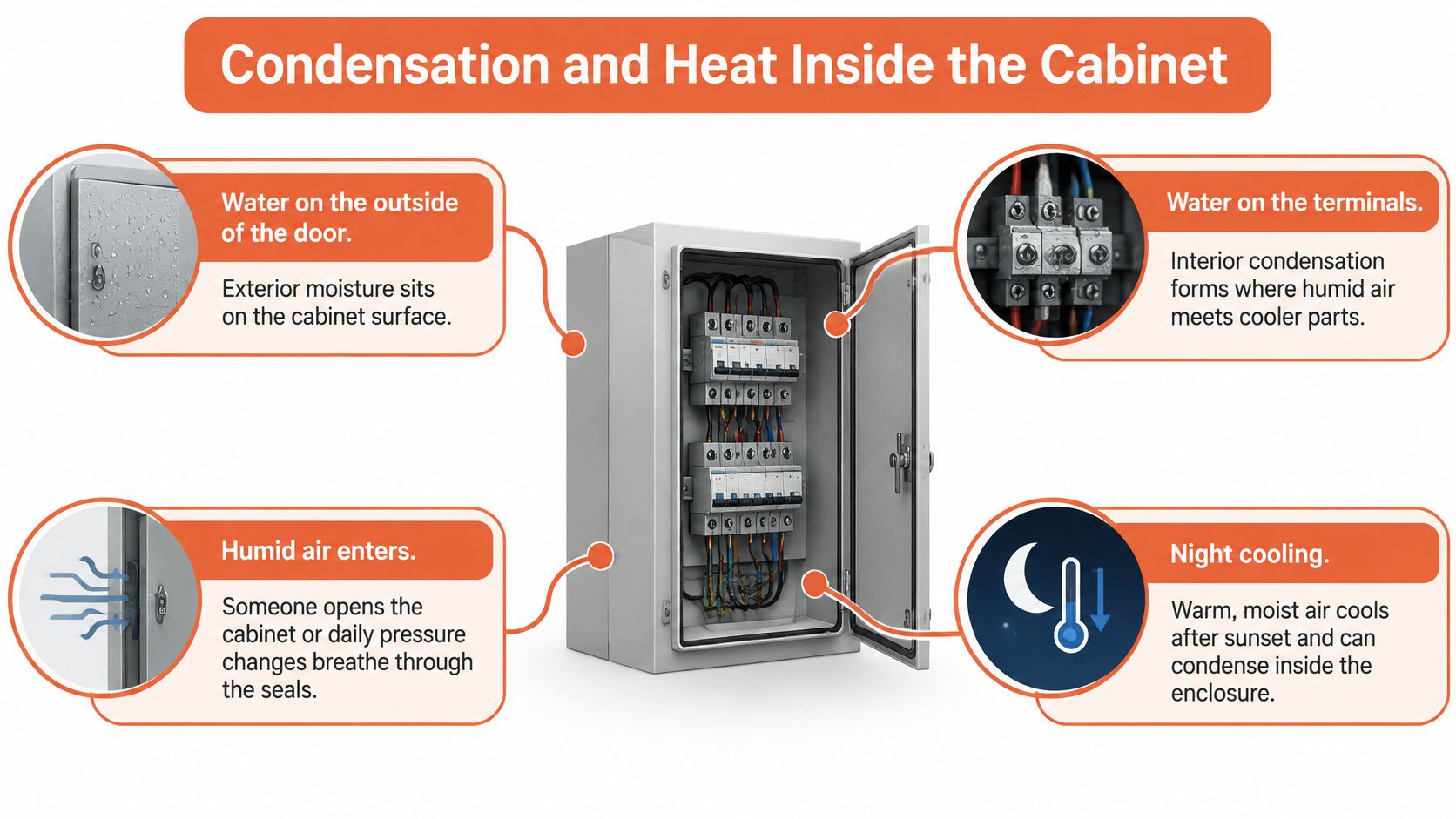
Water on the outside of a door and water on internal terminals are different problems. A cabinet can exclude external water yet contain humid air that later condenses on cooler surfaces.
Humid air enters during maintenance or through pressure-driven air exchange. When temperatures fall overnight or during a seasonal change, internal surfaces can reach the air's dew point. A fine moisture film may appear without a visible leak through the roof, seam, or conduit hub.
The Institution of Engineering and Technology's outdoor-assembly guidance identifies ventilation, internal heating, drainage, and similar measures for humid environments with wide temperature variation, and notes that maintaining the interior approximately 5°C above outside ambient can prevent condensation under relevant conditions. That's a design consideration, not a universal heater setting independent of cabinet load and site conditions.
Select the control for the moisture mechanism
Condensation and heat controls
Condition
Control that fits
Risk if misapplied
Night cooling toward dew point
Controlled heater selected for the enclosure and environment
Uncontrolled heat wastes energy or overheats components
Pressure change draws humid air in
Listed or approved breather or drain compatible with the enclosure rating
An open hole or unsuitable drain invalidates the ingress claim
Door opened in humid weather, then sealed
Dry-out and gasket inspection; desiccant where access is rare
Humid air remains trapped inside
Heat from drives or power supplies
Rated ventilation, a sunshield, or compatible cooling
Field-added fans or filters compromise the approved construction
Washdown plus wide temperature swings
External-water protection plus a separate internal-moisture plan
Treating a water rating as a condensation solution
A thermostat-controlled heater can fit utility controls, solar combiners, EV charging equipment, and industrial cabinets exposed to pronounced day-night swings. Select it using the enclosure's thermal conditions and component limits. Locate it so wiring and temperature-sensitive parts aren't exposed to inappropriate localized heat.
A breather or drain serves a different purpose. It may manage pressure or release small amounts of condensate, but only if the device and installation preserve the required protection. Drilling a hole at the low point isn't an acceptable substitute for an approved drainage arrangement.
Desiccant is reasonable for a sealed cabinet opened infrequently. It requires inspection and replacement or regeneration according to the product instructions. A saturated packet left inside for the life of the cabinet isn't a moisture-control plan.
A tighter seal isn't automatically safer
A higher ingress rating can trap humid air already inside the cabinet. Conversely, ventilation can introduce dust or corrosive contaminants if the design doesn't account for the surrounding atmosphere. Choose between sealing, controlled heating, ventilation, and cooling by evaluating both internal conditions and external hazards.
Solar exposure adds heat even when internal electrical losses are modest. A sunshield may reduce that load without creating another enclosure opening, while a drive cabinet may need engineered cooling. Don't add a fan because the internal air feels hot without checking component temperature limits and the approved assembly design.
IP and NEMA water tests don't validate every real-world thermal cycle. During commissioning, include the following checks:
Gasket compression: Inspect corners, hinge-side contact, and areas around the latch.
Heater control: Verify operation, sensor location, and the specified control setting.
Drain location: Confirm the approved device sits at the intended low point and remains clear.
Early operating inspection: Look for water trails or internal moisture after representative weather changes.
Log whether moisture appears after rain, cleaning, maintenance access, or overnight cooling. That sequence gives maintenance staff a useful diagnostic trail instead of another unexplained moisture report.
Site Examples for Mounting and Penetrations
A site survey should produce drawing notes, not just a rating recommendation. IEC 61969-3 addresses environmental and safety requirements for outdoor enclosures in locations that aren't weather-protected, reinforcing the need to consider the surrounding installation.
These scenarios show where a suitable cabinet still needs project-specific decisions.
Coastal lift station and food-plant wall
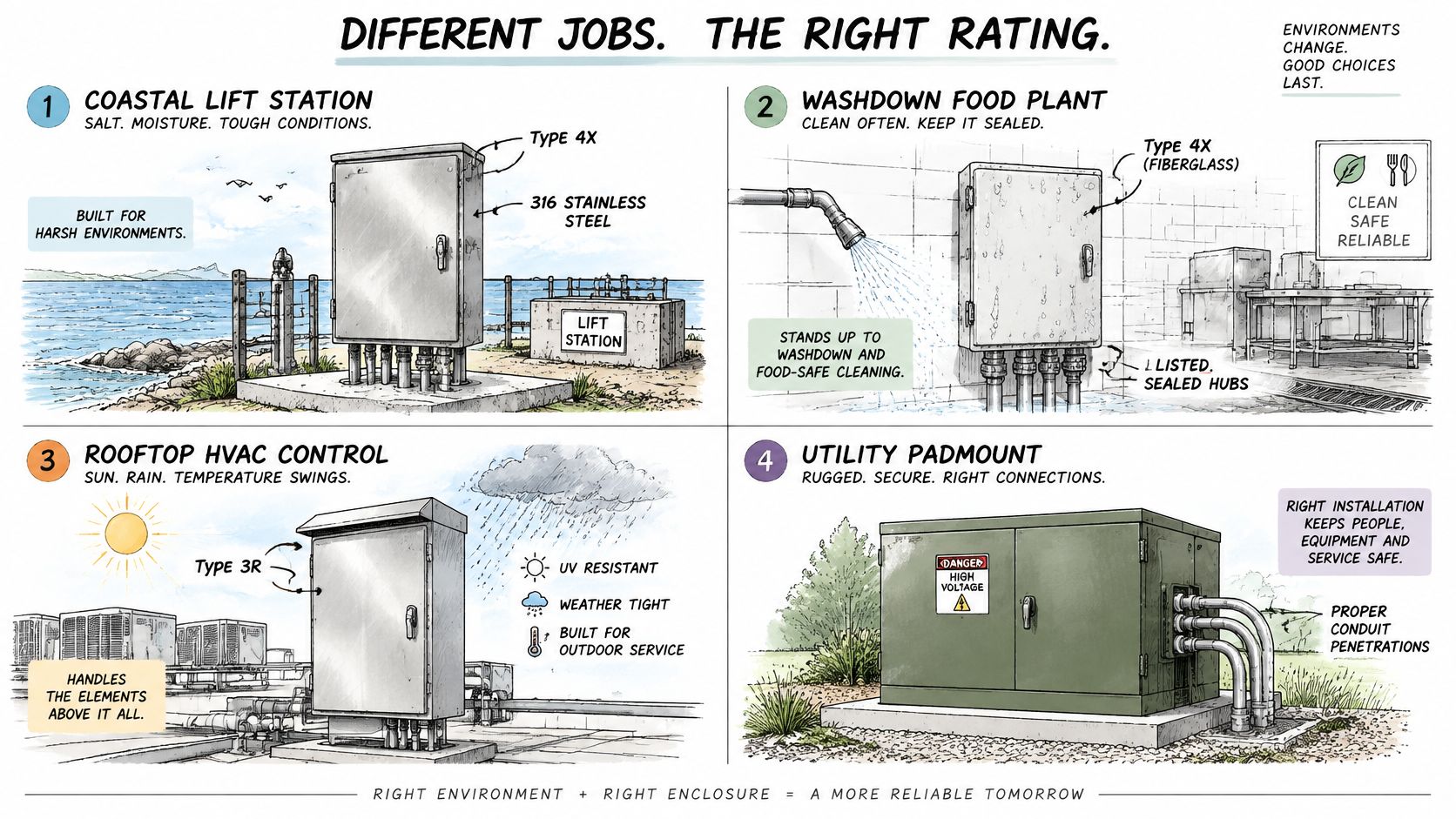
At a coastal lift station, start with corrosion-resistant construction appropriate to salt exposure, such as a suitable stainless alloy or fiberglass system. Evaluate the hubs, mounting hardware, and cable support as part of that selection. Determine elevation from applicable flood information and the project's freeboard criteria, not the position shown in a product photograph.
The drawing note needs the mounting elevation, support arrangement, and sealed-entry schedule. For flood-exposed equipment, distinguish cabinet protection from site-level measures such as watertight secondary barriers and verified penetrations. Battery-storage flood planning provides a useful model: establish the protection level and check the entire protective arrangement.
At a food plant's exterior washdown wall, account for the cleaning stream and the actual chemical used. A corrosion-resistant cabinet with an incompatible viewing window or field-added operator cutout can still be unsuitable. Require the window, operator, and sealing arrangement to be included in the accepted construction.
Add cleaning compatibility and inspection access to the drawing. Leave room for technicians to examine the door seal instead of placing pipework immediately across the opening.
Rooftop combiner and ordinary building wall
A rooftop solar combiner combines sunlight, wind-driven rain, temperature variation, and difficult access. Review the coating or polymer's outdoor suitability, mounting security, and internal moisture control. Cable routing should avoid unsupported entries and water collection around fittings.
Specify a reachable service position and a replacement path. A cabinet that requires dismantling adjacent equipment for removal creates a foreseeable outage problem, even if its ingress protection is suitable.
A building wall exposed only to falling rain may be an appropriate application for NEMA 3R pull boxes. Verify that hose cleaning, salt, and significant dust really are absent rather than assuming that all building exteriors have the same conditions.
Record entry orientation and drainage provisions on the installation detail. Preserve access to fasteners and the cover so inspection doesn't depend on removing unrelated building services.
Keep a site-risk worksheet
An ingress designation doesn't establish protection against wildfire heat, windborne debris, arbitrary flood depth, or inaccessible maintenance. Keep the remaining decisions visible in a compact worksheet:
Hazard: Identify weather, contaminants, cleaning, and credible emergency exposure.
Construction: Name body material, finish, hardware, and accessory compatibility.
Elevation: State the design basis for mounting height.
Drainage: Show approved drainage and routes that avoid water collection.
Access: Provide working access, gasket inspection, and replacement clearance.
Documentation: Retain drawings, approvals, inspection requirements, and replacement lead-time information.
Specify and Source the Complete Assembly
An RFQ should let a supplier quote a buildable assembly without guessing which details the installer will resolve later. The lowest cabinet price isn't a useful comparison if one quotation excludes the hubs, back panel, heater, and modifications needed for the project.
Write the specification around the delivered configuration. Separate mandatory requirements from preferences so procurement can evaluate alternatives without changing the engineering intent.
Put the essential fields in the RFQ
Environmental designation: Required NEMA type or IP code, with the applicable project standard.
Material and finish: Body construction, hardware, coating, and any transparent components.
Electrical and dimensional requirements: Equipment voltage rating, usable interior space, back-panel layout, and cable-entry clearance.
Mounting arrangement: Wall, pole, floor, or freestanding installation, including orientation and support details.
Access and security: Hinge position, door swing, latch, lock, and authorized-access requirements.
Installed accessories: Every hub, gland, window, operator, breather, drain, heater, and back panel.
Ask the manufacturer to confirm in writing that the environmental rating applies to the complete proposed assembly, not merely the unmodified catalog enclosure. Request the listing or third-party test documentation available for that configuration, and resolve discrepancies before release for fabrication.
Control substitutions before they reach the field
Check compliance with the jurisdiction's adopted electrical requirements during submittal review. For government and institutional purchasing, flag Buy American Act or Trade Agreements Act requirements only when the contract imposes them, and request the corresponding documentation before ordering. Don't treat distributor location as proof of product compliance.
Lead time belongs in the approval discussion. If the preferred stainless construction isn't available when needed, fiberglass or another manufacturer's design may be an option, but it can change mounting, thermal behavior, entry methods, and maintenance practices. Obtain the engineer's written acceptance before treating it as interchangeable.
Keep a substitution register showing the proposed part, deviations, supporting documents, approval owner, and delivery commitment. That gives the contractor, panel builder, and facilities team a shared record instead of conflicting email assumptions.
For an electrical enclosure outdoor purchase, the actionable package is straightforward: an exposure description, drawing callout, accessory schedule, and required-by date. Send it to the manufacturer or a distributor with technical sourcing support so the quote addresses the specification rather than the word outdoor.
ATEK Distribution offers BOM review, hard-to-source enclosure and accessory sourcing, manufacturer coordination, and compliance-documentation support. Visit ATEK Distribution with your site exposure, drawing callout, and required-by date to discuss availability and alternatives for engineering approval.
A 5/8-inch-diameter by 8-foot copper-clad steel rod is a common listed ground rod size; 8 feet of soil contact is the code minimum, while diameter must satisfy the listing and project specification. A larger diameter doesn't compensate for insufficient soil contact, and extra length doesn't make an otherwise unsuitable rod acceptable.
For engineers and buyers, ground rod sizes are a system-selection question, not just a catalog lookup. The right purchase includes the electrode, its material and listing, compatible connections, the grounding electrode conductor, and an installation plan suited to the soil.
Rod length and diameter control different parts of the installation. The NFPA 70 development document identifies 2.44 meters (8 feet) of contact with earth as the installation requirement for rod and pipe electrodes. A rod's nominal length does not by itself confirm that the installed electrode achieves the required soil contact.
The 2023 NEC summary from EEPower states that rod or pipe electrodes must be at least 2.44 meters (8 feet) long. Check both the product length and the installed contact with earth.
Common sizes and the checks behind them
The table shows familiar purchasing descriptions, not blanket approvals. Confirm the specified material, listing, and project requirements for the application.
Common ground rod sizes, materials and typical use
Size (diameter x length)
Typical material
Typical application
Listing or specification note
5/8 in x 8 ft
Copper-clad steel
Common listed electrode for residential and light commercial grounding
Confirm listing and required soil contact
5/8 in x 10 ft
Copper-clad steel
Longer soil contact where the design calls for more depth
Confirm listing and availability
3/4 in x 8 ft
Copper-clad steel
Heavier-duty engineered systems
Project specification required
3/4 in x 10 ft
Copper-clad steel
Engineered and federal specifications
Confirm listing and the applicable federal or project specification
5/8 in x 8 ft
Galvanized steel
Sites where the design calls for zinc-coated electrodes
Confirm listing, coating requirements and soil compatibility
5/8 in x 8 ft
Stainless steel
Corrosive soils or projects specifying stainless material
Confirm listing, grade and availability
1/2 in x 8 ft
Manufacturer-specified metal
Limited applications only
Below the standard diameter threshold unless listed
For stainless-steel, copper, or zinc-coated steel rod electrodes, Galvan Electrical's catalog description of NEC requirements states a 15.87 mm (5/8-inch) minimum, unless the rod is listed. A smaller listed electrode and an unidentified metal stake are not equivalent products.
Length and diameter solve different problems
Length controls soil contact and access to deeper soil layers. Diameter affects mechanical strength, resistance to driving damage, and the amount of metal available to withstand corrosion. Neither dimension guarantees a particular ground resistance.
Driving conditions matter. Rocky or compacted ground can make a rod harder to install; bending, a damaged head, or lost cladding can compromise the product. Select the driving equipment and accessories to suit the rod before ordering.
Purchasing rule: Specify diameter, length, base material, coating or cladding, and listing. A size-only description is incomplete.
If a supplier offers a longer rod than the approved item, assess handling clearance, driving equipment, connection details, listing, and the engineer's specification before accepting the substitution. Extra length alone does not establish compliance.
Material and Coating Options Compared
Choose the material for the soil and installation method, not for a general claim that one metal is always better. Copper-clad steel combines a conductive outer layer with a steel core that supports driving. Its suitability still rests on the actual product construction and the site's corrosion exposure.
Galvanized steel uses a zinc coating rather than copper cladding. Coating thickness, soil chemistry, and compatibility with connected metals deserve review before substitution. Neither a copper-colored surface nor a silver finish establishes the electrode's material or listing.
Ground rod materials compared on the criteria that affect selection
Material
Corrosion behavior
Driving and strength
Listing and typical use
Copper-clad steel
Copper outer layer protects a steel core
Steel core supports driving; protect cladding from damage
Common listed option for general grounding
Galvanized steel
Zinc protection; service life is influenced by coating thickness and soil
Steel core supports driving
Confirm coating thickness and listing
Solid copper
High corrosion resistance in suitable environments
Softer metal; confirm suitability and driving method for rocky soil
Confirm listing and obtain a project-specific price
Stainless steel
High corrosion resistance in many soils; grade and chemistry matter
Strong; driving suitability requires grade and product review
Confirm listing and grade with manufacturer
Painted or enameled steel
Nonconductive coating makes it unsuitable as a made electrode
Mechanical strength doesn't resolve the coating problem
Excluded where OSHA prohibits nonconductive coatings
Read the construction details
A supplier data sheet should identify the base metal, coating or cladding type, applicable listing reference, and intended burial conditions. Don't infer coating thickness from a product photograph or treat solid copper and copper-clad steel as alternate descriptions of the same item.
Ask the manufacturer to confirm:
Corrosion suitability: Whether the proposed construction is appropriate for the site's known soil exposure.
Driving accessories: Which heads, couplers, and tools are compatible with the electrode.
Connection compatibility: Which clamps accept both the rod material and the specified conductor.
Commercial terms: Current price, available quantity, and lead time for the exact catalog number.
Solid copper and stainless steel can be legitimate engineered choices, but they aren't universal upgrades. Compare the complete installed cost, including driving difficulty, accessories, documentation, and replacement risk. Treat unquoted prices and unconfirmed delivery dates as unknown, not as estimates suitable for a purchase order.
Installing Ground Rods to Depth in Real Soil
A correct catalog selection can still produce an unacceptable installation. Before driving begins, qualified personnel should confirm underground utility locations, available working space, the approved electrode layout, and the installation method.
Use this field sequence to coordinate the rod, soil location, and final inspection.
Installation sequence
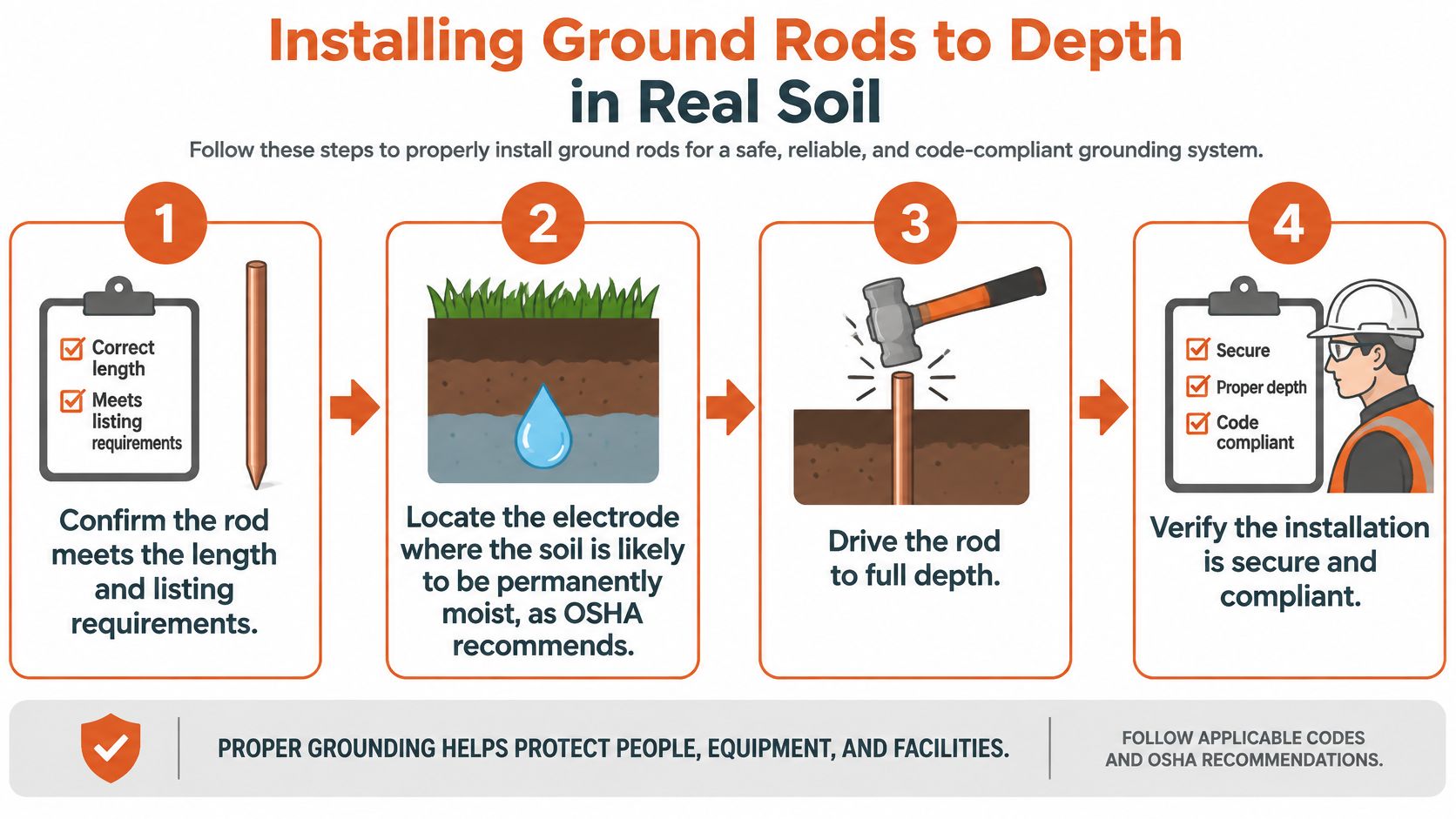
Verify the electrode before driving. Compare its label and submittal with the approved material, dimensions, and listing. Discovering a mismatch after burial makes identification and correction harder.
Confirm the installation location. Choose the approved position with attention to persistent soil moisture, underground services, access, and conductor routing. Convenient placement beside the equipment isn't enough if the soil or layout is unsuitable.
Drive to the required installed depth. Use a compatible driving head and appropriate equipment. Don't cut off a refused rod or leave it partly exposed and assume its original length still proves compliance; rock refusal requires an approved installation response.
Make the conductor connection. Use a listed clamp compatible with the rod, conductor, and burial conditions, tightened to the manufacturer's instructions. A clamp that physically fits isn't necessarily suitable for the application.
Inspect and test as specified. Check mechanical security, conductor protection, and the required resistance test before acceptance. Record deviations while the installation remains accessible.
OSHA's construction grounding guidance requires made electrodes to be free of nonconductive coatings such as paint or enamel, recommends installation below the permanent moisture level where practicable, and requires a single rod, pipe, or plate electrode exceeding 25 ohms to be supplemented by another electrode at least 6 feet (1.83 meters) away. That supplemental-electrode rule isn't a guarantee that the completed system will meet a more demanding project target.
Resolve soil problems through design
Soil resistivity, moisture, corrosion exposure, and electrode geometry affect the result. A longer rod may reach more favorable soil, but increasing length or diameter won't reliably resolve every site condition. Sensitive industrial installations may require an engineered electrode arrangement rather than a larger version of the original purchase.
The following video provides additional installation context; use the applicable code, manufacturer instructions, and engineer's requirements for the actual work.
The grounding path must remain permanent and continuous. Give connections and routing the same inspection attention as the buried electrode.
Sizing the Grounding Electrode Conductor
The grounding electrode conductor isn't sized from the rod diameter. Increasing the electrode's diameter doesn't authorize a smaller conductor, and specifying a heavy conductor doesn't correct an unsuitable electrode.
EC&M's explanation of NEC Section 250.66 states that sizing generally follows the largest ungrounded service-entrance conductor, while the connection solely to rod, pipe, or plate electrodes need not be larger than 6 AWG copper or 4 AWG aluminum under the cited rules. This is a limit on the size required for that connection, not a prohibition against using a larger conductor or blanket permission to use either material in every location.
Separate the rod connection from the full system
A service can include connections to metal water pipe, a concrete-encased electrode, and other qualifying electrodes. The rod-specific sizing provision doesn't automatically govern those connections. Review each conductor segment by its function and termination points.
On the bill of materials, identify the rod connection separately from the other grounding electrode conductors and bonding jumpers. Include conductor material, connection method, physical protection, and terminal compatibility rather than leaving the installer to interpret a generic grounding-wire line item.
A conductor exception applies to a defined connection. It doesn't replace a review of the complete grounding electrode system.
Raceway bonding also deserves its own line of review. A split grounding bushing addresses a different connection detail from the electrode clamp; confirm the fitting's function and compatibility instead of treating grounding accessories as interchangeable.
Questions before conductor release
Which electrodes are present? Identify the actual system, not only the rod shown in a purchasing schedule.
What service conductors govern sizing? Obtain the approved service information rather than estimating from equipment appearance.
Is this connection solely to rods? Confirm the conductor's complete route and what it connects along the way.
Will the termination accept it? Check conductor material and size against the clamp or lug documentation.
What local requirements apply? Resolve authority-having-jurisdiction interpretations before ordering.
This separation makes BOM review more useful. It prevents a correct rod connection from being mistaken for a correctly specified grounding electrode system.
Matching Rod Size to Each Application
An electrode suitable for a building service isn't automatically the right purchase for a generator, fence energizer, or sensitive equipment installation. Identify the governing document before selecting the catalog item. The application determines which questions need engineering review and which require manufacturer confirmation.
For a service entrance, review the grounding electrode system as a whole. For a portable generator, establish how the generator will supply loads and what the manufacturer requires before assuming that a separate rod is necessary.
Ground rod sizing questions by application
Application
Typical electrode arrangement
Sizing question to confirm
Governing reference
Service entrance
Rod plus other electrodes present in the system
Which other electrodes are present, and what conductor sizing applies?
NEC and authority having jurisdiction
Portable generator
Rod or system as the generator manual directs
Does this operating configuration require an electrode, and what does the manual specify?
Generator manufacturer and applicable code
Electric fence
Rod count and spacing per energizer design
What rod size and count does the manufacturer specify for these soil conditions?
Energizer manufacturer instructions
Industrial or sensitive equipment
Multiple electrodes or engineered system where required
Can the proposed arrangement meet the specified resistance target?
Engineer specification and applicable code
Federal or public-sector project
Electrode defined by the contract specification
Are diameter, length, material, and required listing matched exactly?
Project specification
Application details that change the order
Fence grounding is part of the energizer's operating arrangement. Obtain the manufacturer's electrode material, count, and layout requirements rather than importing a building-service detail into that application.
For industrial equipment, distinguish an equipment manufacturer's performance requirement from a generic electrode description. If the specification calls for a measured result, request the acceptance method and responsible testing party before releasing the order.
Public-sector procurement adds a documentation issue: a commercially available substitute can still conflict with the contract. Submit the proposed alternative with a side-by-side comparison of construction, listing, dimensions, and connection accessories. Availability alone isn't approval, even when the substitute appears mechanically more substantial.
Measuring Ground Resistance and Soil Conditions
A dimensionally acceptable electrode doesn't establish the resistance of the installed system. Soil resistivity describes how strongly the soil opposes current flow, while electrode resistance describes the installed electrode's electrical relationship with the surrounding earth. Buyers need the distinction because soil investigation and installation acceptance are different tasks.
A fall-of-potential test commonly uses auxiliary test electrodes placed away from the electrode under test. The test technician follows the instrument manufacturer's placement and measurement procedure, checks whether the test geometry is valid, and confirms the method with the engineer.
Choose a test method that fits the site
Space restrictions, buried conductive infrastructure, and parallel grounding paths can affect the measurement. A clamp-on tester isn't automatically a substitute for a fall-of-potential test, particularly where the required return paths aren't present. Specify an appropriate instrument and method rather than accepting any displayed resistance value.
For preconstruction investigation, a four-pin method such as the Wenner method estimates soil resistivity at different probe spacings. Engineers can use those measurements to evaluate whether deeper electrodes, a distributed arrangement, or another engineered solution is appropriate. Use applicable guidance such as IEEE 81 with the project's testing requirements.
Test-record check: Keep the method, instrument identification, electrode layout, soil conditions, and measured result together. An isolated resistance value is difficult to evaluate later.
Turn measurements into procurement decisions
Moisture and temperature can change readings. A measurement made after rain may not represent dry conditions, so record the environmental context and let the engineer determine whether further testing is needed.
Agree on the acceptance test before installation and complete it before energization where the commissioning plan requires. Retain the result with the electrode submittal and as-built layout.
Procurement should request the resistance target, test method, and corrective-work responsibility before fixing the electrode quantity. If testing identifies an unacceptable result, obtain an approved design response rather than purchasing additional rods without a layout.
Sizing Mistakes That Cause Rework
Most purchasing mistakes begin with a description that sounds complete but omits an acceptance criterion. A line item reading ground rod leaves the receiving team without enough information to distinguish a conforming product from a convenient substitute.
Use the following checks before shipment, while corrections can still be handled through documentation rather than excavation.
Treating extra length as equivalent construction. A longer but thinner rod can behave differently during driving and may not meet the approved listing or specification. Compare diameter, construction, and listing independently before approving the change.
Ordering conductor from rod size. This can leave other electrode connections incorrectly specified even when the rod connection is acceptable. Review the grounding diagram and identify each conductor's endpoints on the BOM.
Accepting an unidentified surface coating. Paint, enamel, metallic plating, and bonded cladding aren't interchangeable. Request the manufacturer's material description instead of accepting a sales photograph as evidence.
Buying an electrode before establishing the performance requirement. An apparently economical purchase can lead to redesign when the installation misses its acceptance target. Confirm the testing plan and engineered layout before locking in the quantity.
Using an incomplete distributor listing. Missing diameter, length, material, or standard leaves the order open to interpretation. Ask for the manufacturer catalog number, data sheet, and required compliance documentation.
Leaving the specification off the purchase order. Later substitutions become harder to assess when the order identifies only a commodity name. Reference the approved submittal and record any accepted alternative in writing.
Make receiving inspection practical
Give the receiving team a short acceptance package: approved catalog number, identifying dimensions, material description, required markings, and accessory list. They shouldn't have to interpret the electrical design to detect the wrong shipment.
Keep damaged products separate for disposition. A bent rod, damaged connection surface, or compromised cladding warrants review before use, not an assumption that burial will make the damage irrelevant.
The useful purchasing habit is simple: resolve ambiguity before the rod ships. Written approval is easier to manage than a field argument over whether an unreviewed substitute is close enough.
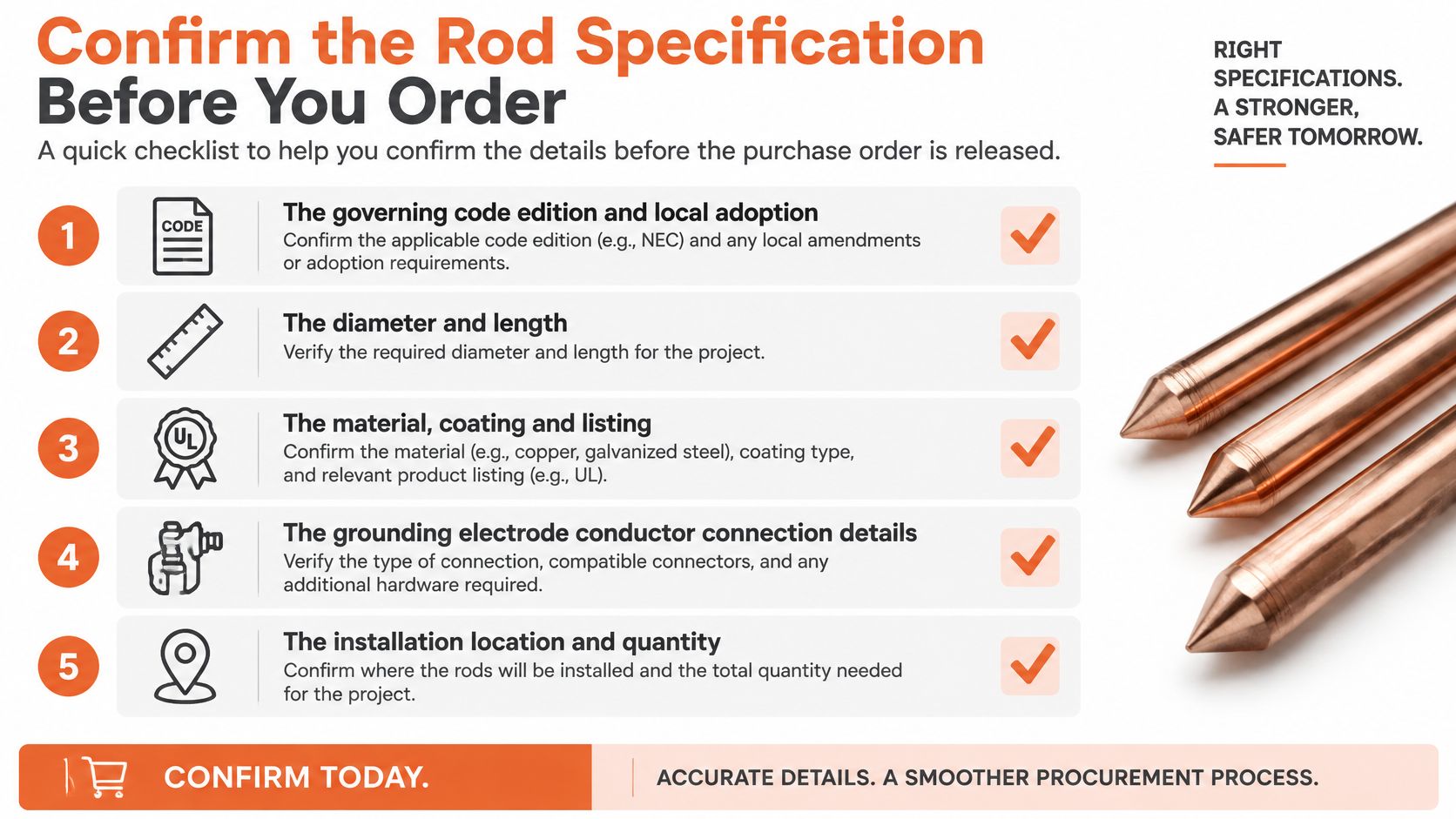
Confirm the Rod Specification Before You Order
The best ground rod specification connects the design requirement to a product that can be identified, installed, inspected, and documented. Release the order only when the responsible parties agree on those details.
Local adoption matters as much as the code edition named in a general reference. For Minnesota projects, the discussion of Minnesota NEC adoption changes is a starting point for identifying questions to verify with the permitting authority, not a substitute for that authority's requirements.
Purchase-order release checklist
Governing requirements: Record the adopted code edition, local amendments, utility requirements, and applicable project specification.
Dimensions: State diameter and length explicitly rather than relying on a catalog family name.
Construction and listing: Identify base metal, coating or cladding, required listing, and manufacturer documentation.
System connections: Confirm conductor sizes, clamp compatibility, burial suitability, and any required physical protection.
Performance and layout: Record the resistance target, test method, installation locations, and approved electrode quantity.
Substitution control: Name the approval authority and retain the accepted alternative with the reason for substitution.
Use this checklist when reviewing the order and the supplier's acknowledgment.
Keep alternatives tied to approval
When the specified item is delayed, compare the proposed replacement against each acceptance criterion. Confirm accessory compatibility and documentation availability at the same time, so an approved rod doesn't arrive without a usable connection method.
Ask the sourcing partner to coordinate unresolved construction or listing questions with the manufacturer. Engineering approval should remain with the designated project authority; distributor support should make that decision better documented, not bypass it.
Before comparing ground rod sizes or requesting a quote, answer the buyer's first question: Is the specification set by the code, the engineer, or the manufacturer's instructions?
ATEK Distribution can help review rod, clamp, and conductor consistency on your BOM, coordinate manufacturer documentation, and source alternatives for project approval when specified components are delayed. Visit ATEK Distribution with your grounding specification, required quantities, and delivery schedule to request project-specific sourcing and quotation support.
Power issues accounted for 45% of impactful data-center outages in the Uptime Institute's 2025 Global Data Center Survey, down from 54% in 2024. That's a useful warning for anyone specifying redundant power supplies: buying additional hardware isn't the same as removing the failure path. The meaningful test is whether the load keeps running when the defined component, feed, or supply system fails.
Why Redundant Power Supplies Matter Before the Panel Is Drawn
Within power-related IT-service outages, the same Uptime Institute survey identified UPS failures as the leading cause at 42%, followed by transfer-switch or utility failures at 36% and generator failures at 28%. Those findings concern data centers, not industrial control-panel failure rates, but the engineering lesson applies: redundant capacity doesn't eliminate shared dependencies.
A second supply won't protect a load if both supplies lose their common input. Shared batteries, controls, transfer equipment, and upstream distribution can defeat otherwise healthy equipment. Procurement therefore needs a functional requirement before it needs a manufacturer part number.
Define the failure before specifying the equipment
Redundant power supplies provide additional capacity and an arrangement that keeps the required load operating after a defined failure. The definition must name the boundary: a failed module, a lost feed, or the loss of an entire supply system.
Before fixing the BOM, answer these questions:
Failure scope: Which specific event must the load survive, and which events remain outside the design?
Surviving load: Must every connected device remain energized, or can the control system shed nonessential loads?
Maintenance allowance: Can the process stop for replacement, or must technicians isolate equipment while the load continues operating?
These answers affect more than supply wattage. They determine distribution paths, isolation provisions, alarm wiring, access, and the replacement procedure.
Separate continuity from power conditioning
A UPS addresses a different set of operating conditions from a duplicated DC supply. HighFlow Energy's explanation of how an uninterruptible power supply works is a useful primer when deciding where stored-energy support belongs in the architecture.
Likewise, investigate power quality issues before treating repeated supply trips as evidence that another supply is needed. Voltage disturbances, unsuitable protection, and input conditions require their own corrective actions.
Design rule: Specify the failure the load must survive, not simply the number of supplies the cabinet must contain.
Topology follows from that failure scope. Availability targets, output decoupling, post-failure load calculations, and network dependencies then establish whether the proposed arrangement meets it.
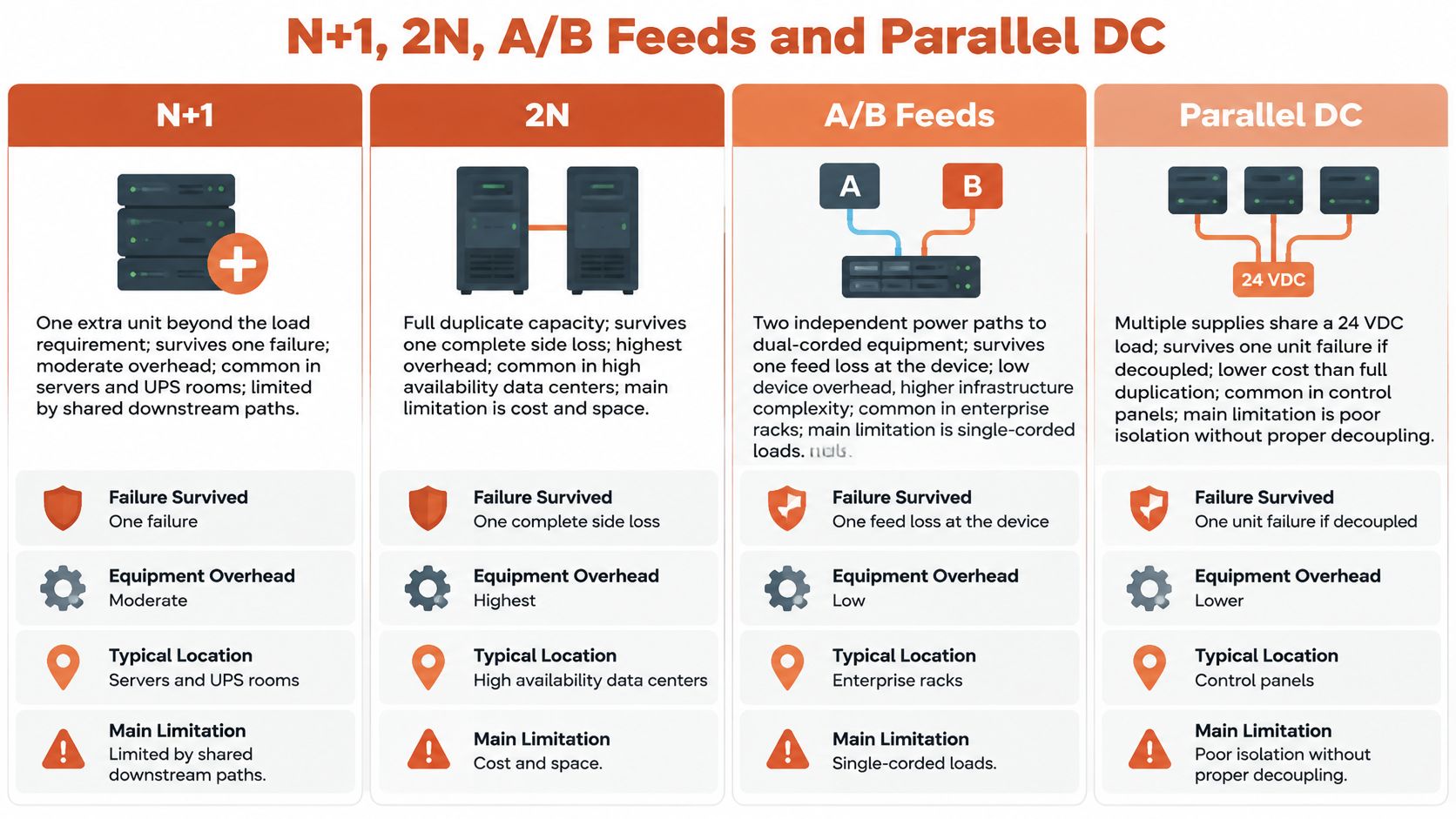
N+1, 2N, A/B Feeds and Parallel DC
Redundancy topologies by failure scope and overhead
Topology
Failure survived
Equipment overhead
Typical use
Main limitation
N+1
One unit or module
One spare beyond the load requirement
Modular UPS, DC supply groups, process controls
Shared bus, controller, or enclosure can still fail the group
2N
Loss of an entire supply system
Complete duplicate system, about 100% added capacity
Data centers, critical facilities
Highest cost and maintenance scope
A/B dual feed
Loss of one feed or distribution path
Each path sized for the full load
Dual-corded IT and critical loads
Transfer equipment and upstream independence remain critical
Parallel 1+1 DC
One DC supply output failure
One equal-rated supply plus redundancy module
24 VDC control panels and automation
Requires output decoupling and separate input protection
The equipment overhead in this comparison describes the architecture, not a project cost estimate. A duplicate supply system also needs distribution, isolation, monitoring, and service access.
Capacity redundancy versus system redundancy
In N+1, N is the number of operating units required to carry the design load. The additional unit provides capacity after a module becomes unavailable. This works well when modular equipment can distribute the demand among the surviving units.
The limitation is the boundary around that capacity. A spare module doesn't replace a failed common output bus or controller. Review the group's shared components before assigning a system-level reliability benefit to its spare capacity.
2N duplicates the complete required supply capacity. Each system must support the load independently, including its applicable operating and derating conditions. It offers a broader failure boundary than module redundancy, but brings more equipment to inspect, test, document, and maintain.
Independence needs evidence. Separate labels on matching cabinets don't establish separate upstream sources or control paths.
This comparison graphic summarizes the architectural distinctions.
Distribution redundancy versus a parallel DC pair
A/B feeds describe separate power paths to the equipment. They don't, by themselves, establish how much reserve generation or UPS capacity exists upstream. Dual-corded equipment must operate correctly when either feed disappears; single-corded equipment needs a suitable transfer arrangement if it's to benefit from both paths.
Confirm the load's actual input behavior. A device that normally draws from both inputs may place substantially more demand on the surviving path after a failure.
A parallel 1+1 DC arrangement is narrower. It protects a common DC load against a supply failure when the outputs are properly isolated and the survivor has sufficient capacity. The common output wiring remains a separate design concern.
Choose the lowest-overhead arrangement that addresses the required event. Don't buy complete duplicate infrastructure to solve a replaceable module problem, and don't describe a spare module as protection against losing an entire distribution path.
Availability Tiers and What the Downtime Figures Mean
The Uptime Institute tier framework, summarized in an Electric Power Research Institute publication, associates Tier I through Tier IV with approximate availability levels of 99.67%, 99.74%, 99.98%, and 99.995%, respectively. The table translates those rounded percentages into approximate annual downtime; these are reference calculations, not a guarantee of site performance.
Uptime tiers, power paths and annual downtime
Tier
Power path design
Approximate availability
Approximate annual downtime
Tier I
Single power path, no redundant components
99.67%
About 28.9 hours
Tier II
Single distribution path with redundant components
99.74%
About 22.8 hours
Tier III
Multiple power paths, redundant components, concurrent maintainability
99.98%
About 1.75 hours
Tier IV
Multiple active paths, fault-tolerant architecture
99.995%
About 26.3 minutes
The distinction between Tier II and Tier III is particularly useful during design review. Adding redundant components to a single distribution path doesn't necessarily let maintenance personnel remove that path from service.
Maintainability is an operating requirement
Concurrent maintainability means the architecture allows required maintenance without shutting down the supported load. That demands suitable isolation points, available capacity, workable procedures, and access to the equipment being serviced.
For a facility that can schedule production shutdowns, a simpler architecture may be appropriate. For continuous operations, planned maintenance can be as important a design driver as unexpected failure. The engineering team needs to evaluate both.
A tier describes the facility architecture, not an individual supply's mean time between failures, or MTBF. Installing a highly rated component in a single distribution path doesn't change the path's maintainability or remove its common failure points.
Convert the target into purchasing requirements
An availability objective becomes useful when engineers translate it into requirements procurement can verify:
Topology: Define whether reserve module capacity or independent supply systems are needed.
Capacity margin: Establish the available capacity during failure and maintenance conditions.
Transfer method: Confirm how the load receives the alternate source and whether it tolerates the transition.
Maintenance procedure: Identify what can be isolated, who performs the work, and what remains energized.
Don't use an annual downtime figure as permission for one interruption of that duration. A process may tolerate scheduled maintenance but not an abrupt control-power loss, even if both occupy the same amount of time.
Set allowable downtime and interruption behavior first. Then select the architecture that supports those requirements, rather than assigning an availability label after the equipment has been purchased.
Decoupling and Sizing 24 VDC Redundant Supplies
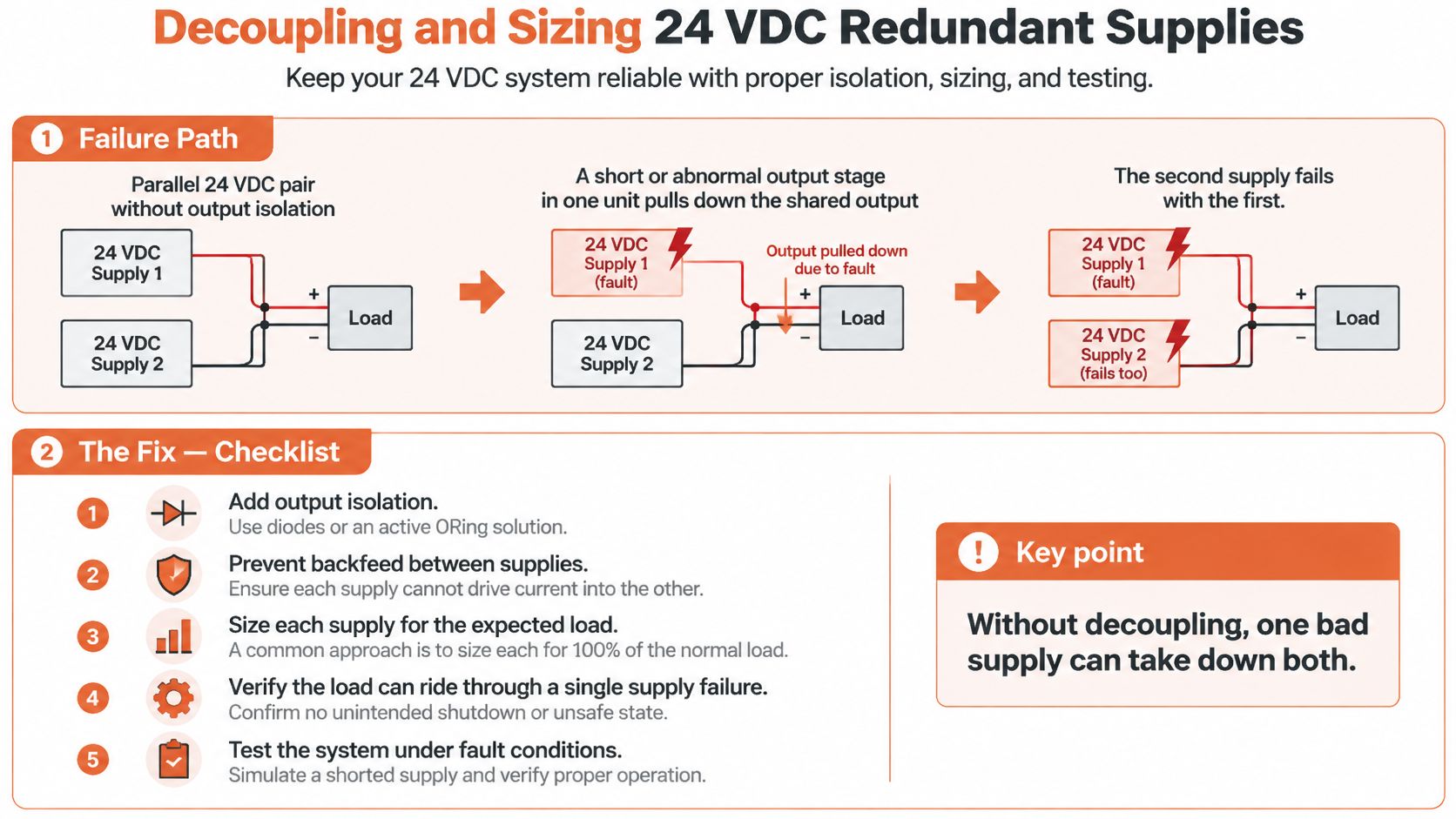
A parallel DC pair without output isolation can fail through its shared output connection. A short or abnormal output stage in one supply may pull down the common bus, leaving the healthy supply unable to maintain load voltage.
Rockwell Automation's redundancy application guidance calls for electrical decoupling, separate input protection, and individual supply monitoring. A redundancy module or suitable decoupling diodes prevents the healthy unit from feeding a fault through the failed supply's output.
Check isolation before adding capacity
Start at each output terminal and trace the connection to the load. Identify where reverse current is blocked, how the isolation device behaves under a fault, and whether the common output connection remains accessible for inspection.
A MOSFET redundancy module can provide the required output isolation, but its suitability still needs checking. Confirm input-channel ratings, total output rating, permitted voltage range, thermal limits, terminal capacity, and the manufacturer's required wiring arrangement.
The failure mechanism and corrective checks are illustrated below.
Give each supply its own input fuse or breaker. Coordinate protection so a fault in one branch doesn't unnecessarily disconnect the healthy branch; installing separate devices doesn't prove selectivity.
Use the industrial fuse selection guide to support review of fuse characteristics, then check the actual supply instructions and upstream protective-device information. Input inrush, interrupting capability, conductor protection, and the available fault current all need appropriate consideration.
Where practical, connect supplies to different phases or independent mains circuits. If phase-loss operation is required, verify that capability for the selected three-phase supply under the intended load and operating conditions rather than assuming it from the input designation.
Calculate the load after failure
Rockwell Automation's redundancy reference manual illustrates a load of up to 10 A supported by two 10 A supplies and a dual-input MOSFET redundancy module. The important arithmetic is what remains available after a supply fails, not the sum of the installed nameplate ratings.
The following worked examples use those supply ratings and assume equal current sharing, no derating, and an appropriately rated isolation arrangement. Percentages are calculated against each supply's nameplate current, not a guaranteed operating margin.
Load share in normal operation and after one failure
Load
Topology
Units installed (10 A each)
Load per unit normally
Load per unit after one failure
10 A
Single supply
1
10 A (100%)
No power, no redundancy
10 A
1+1
2
5 A (50%)
10 A (100%), no margin
20 A
Intended 1+1, insufficient capacity
2
10 A (100%)
Cannot carry the load, undersized
20 A
N+1
3
About 6.7 A (67%)
10 A (100%), limited margin
The intended 1+1 arrangement supporting the larger load can meet its steady-state demand under the stated assumptions, but it isn't redundant. Both supplies are required for normal operation. Calling it redundant on a drawing doesn't create surviving capacity.
A supply pair can have enough combined capacity to run the load and still have no capacity redundancy at all.
Equal sharing is also an assumption to verify, not an automatic result of parallel wiring. Output-voltage differences and the supply's sharing method affect how much current each unit delivers.
Apply derating and review the complete BOM
Use the manufacturer's curves for the actual enclosure temperature, input conditions, mounting orientation, and required clearances. A nameplate rating isn't a substitute for the permitted continuous output in the installed environment.
Check transient demand as well as steady-state current. Contactors, field devices, and capacitive loads can impose demands that aren't apparent from a simple list of nominal operating currents. Confirm the supply's overload behavior and the load's voltage tolerance together.
The component-level BOM review should cover:
Output isolation: Specify the redundancy module or decoupling devices and their channel and output ratings.
Input protection: Include an individual protective device for each supply, with coordination reviewed.
Voltage settings: Equalize outputs as instructed and enable parallel-use mode where supported.
Monitoring: Specify separate DC-OK contacts or equivalent signals and the required control-system inputs.
Approved substitutions: Match isolation behavior, operating ratings, terminals, monitoring, and manufacturer compatibility, not just nominal voltage.
Installation documentation: Include wiring instructions, applicable compliance documentation, and the final approved arrangement.
Order the supplies and redundancy module as a coordinated assembly of compatible components. A substitute that fits the DIN rail may still change current sharing, alarm behavior, thermal requirements, or protection.
Final selection and sizing must follow manufacturer instructions, applicable NEC and UL requirements, and the project engineer's review. Redundancy doesn't waive ordinary requirements for safe installation, conductor sizing, protection, or service access.
Testing and Monitoring a Redundant Supply System
A redundant arrangement remains unproven until personnel verify its behavior under the intended operating conditions. A healthy common output voltage alone doesn't establish that every supply is available.
Wire each supply's DC-OK signal to a separate PLC or control-system input. A failed unit should generate an actionable maintenance alarm while the remaining capacity still supports the process. Treat loss of all required control power as a shutdown condition, with responses determined by the process safety and controls design.
Establish a commissioning baseline
Use a DC-capable clamp meter on each individual output conductor to measure load current. Record operating conditions, current distribution, and output voltage against the manufacturer's permitted limits.
Check the alarm at the operator interface, not just at the supply terminal. The maintenance team needs a clear equipment identifier and response instruction.
Test the intended failure safely
A planned test should include these steps:
Authorize the work: Confirm the maintenance window, supported load, isolation method, and recovery procedure.
Verify indication: Isolate a supply using the approved method and confirm its individual alarm reaches the control system.
Check the survivor: Measure current and output voltage while the remaining supply supports the required demand.
Restore and document: Return the isolated unit to service, verify sharing and alarm clearance, and log the results.
Don't simulate an output short unless the manufacturer and an engineered test procedure explicitly permit it. Don't assume a removable module is hot-swappable.
All testing must follow manufacturer instructions and site lockout procedures and be performed by qualified personnel. Energized measurements require the site's applicable electrical safe-work practices.
This test exercises the supply layer only. Upstream distribution, transfer equipment, and communications paths require separate acceptance checks, with their own failure conditions and recovery criteria.
Failures That Duplicate Hardware Cannot Prevent
A shared upstream breaker can disconnect both supplies without either supply failing. The same boundary problem applies to the shared batteries, transfer equipment, and feeds identified at the start: duplicated components don't protect against every dependency outside their terminals.
Controllers, firmware, and maintenance practices add less visible common-cause paths. A common controller may issue the same incorrect command to both sides, while identical firmware can expose both units to the same triggering condition.
Review control and maintenance independence
Mounting supplies in the same enclosure also exposes them to common environmental conditions. Excessive temperature, contamination, or damage to a shared wiring route can affect both units together.
The maintenance procedure deserves the same scrutiny as the schematic. Ambiguous disconnect labels, shared alarm bypasses, or a work instruction that isolates both paths can defeat an otherwise sound design.
Control dependency: Identify common controllers, settings, communications, and firmware assumptions.
Work boundary: Mark which devices and terminals remain energized during replacement.
Disturbance exposure: Review grounding and surge protection separately from capacity redundancy; the surge protection rating guide supports that selection discussion.
Keep network resilience separate
IEC 62439-3 defines Parallel Redundancy Protocol (PRP) and High-availability Seamless Redundancy (HSR) for industrial Ethernet, specifying switchover with zero recovery time when a network element fails.
PRP transmits duplicated information over separate networks. HSR uses two-port nodes in a ring or multi-port nodes in a meshed network. These mechanisms differ from a conventional standby link that must detect a fault and reconverge.
Their scope matters. A redundant DC supply can't compensate for a failed network switch or cable, and PRP or HSR can't correct a common upstream power fault. A substation controller may need independent provisions for both.
Review boundary: Ask what keeps the process working, not merely what keeps the power-supply output energized.
Trace each failure path from the utility connection through distribution, control power, controller, communications, and the return path. Assign a protective or redundant element to each required failure case, then mark any dependency without an independent backup. That marked drawing is more useful than a general statement that the panel is redundant.
Choosing the Right Topology for Your Load
Select redundant power supplies around the equipment's operating consequences, not around a preferred cabinet layout. The right arrangement for a replaceable control-power unit isn't automatically the right arrangement for a critical facility distribution system.
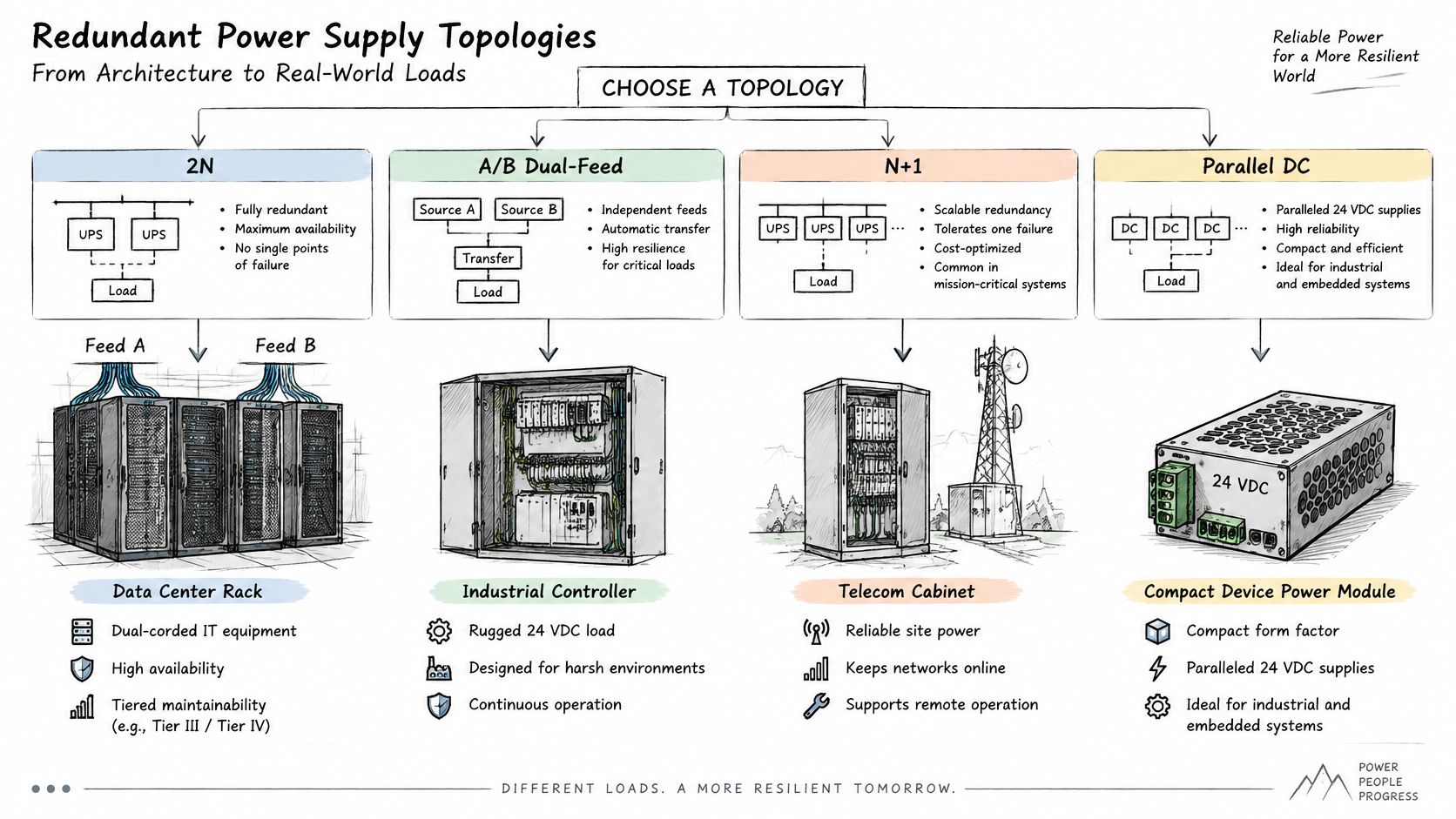
Use the topology diagram to compare where capacity and distribution-path separation belong.
Match the arrangement to the application
For data centers with dual-corded IT, consider independent A/B distribution and complete duplicate supply capacity where the availability and maintenance requirements justify them. Confirm the equipment can operate on either input and that maintenance personnel can isolate the intended side safely.
For industrial control panels, an isolated parallel DC arrangement is often the appropriate starting point. The deciding issue is whether uninterrupted control power is required during a supply failure, rather than whether the panel has room for another DIN-rail device.
For process plants using modular UPS systems, N+1 can provide reserve capacity without duplicating the complete installation. Apply the same logic carefully to drive systems: an additional drive doesn't automatically provide a transferable operating path for a motor or process train.
For substations and real-time controls, specify the power and network requirements separately. If the communications architecture requires PRP or HSR, include compatible network equipment and an acceptance procedure alongside the control-power design.
The video below provides an additional visual reference for the power-system discussion.
Release a procurement-ready requirement
Before placing an order, record the application-level decisions:
Required survival event: Identify whether the requirement covers a module, feed, supply system, or combined maintenance condition.
Allowable interruption: State whether the load permits a transfer interruption and whether planned shutdowns are available.
Essential load boundary: Identify which process functions must remain available and whether load shedding is permitted.
Network obligations: Document substation or real-time communications requirements separately from power continuity.
Approval authority: Name who accepts substitutions and signs off the final architecture.
Use the component-level decoupling and sizing checklist to complete the equipment schedule. Keep calculations, drawings, approved alternates, and operating procedures consistent through procurement and commissioning.
The purchasing decision is ready when the team can describe the failed condition, show the remaining capacity, and demonstrate how technicians restore redundancy safely. Extra equipment without those answers is an expense, not a verified continuity strategy.
ATEK Distribution can support BOM review, source hard-to-find redundancy modules and protective devices, and coordinate manufacturer review of proposed alternatives against the required isolation, ratings, monitoring, and compliance documentation. Send your load list, allowable downtime, and bill of materials to ATEK Distribution for project-specific sourcing support and a quote for your redundant power supplies.
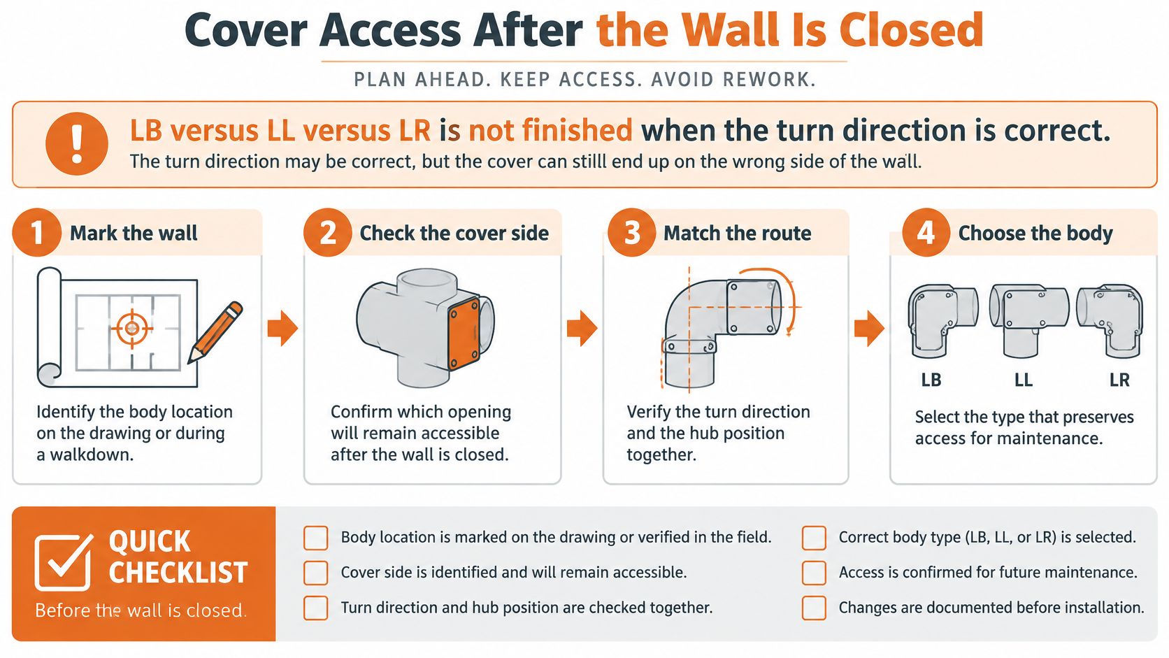
The wall is finished, the raceway is installed, and the crew is ready to pull conductors. Then someone notices that the LB cover faces the studs. The turn fits the drawing, but nobody can reach the opening without disturbing the finished work or opening the raceway.
That's the distinction that matters when choosing conduit body types. The letter determines the route, but cover access, pulling space, and the intended wiring work determine whether that fitting will serve the installation.
A conduit body is a separate portion of a conduit or tubing system that provides interior access through a removable cover at a raceway junction or terminal point. Contractors use it to pull and inspect conductors, change direction, and, where the product and installation permit, make splices without installing a full junction box.
The enclosure classification is important. OSHA's electrical definitions specifically exclude FS and FD boxes, along with larger cast-metal and sheet-metal boxes, from the conduit-body category. Those products aren't interchangeable pull points just because each has a removable cover.
Read the letter from the cover side
Use a consistent viewing position: stand with the cover facing you. LL leaves left, LR leaves right, and LB leaves through the back, opposite the cover. Keep that convention on sketches, takeoffs, and purchase descriptions so the installer and buyer aren't interpreting the same letter from opposite sides.
Conduit body types by path and cover
Body
Hubs
Path relative to cover
Typical routing job
Type C
2, inline
Straight through under the cover
Pull or inspection access with no change of direction
Type LB
2
90 degrees out the back, opposite the cover
Turn into or out of a wall while the cover stays on the open face
Type LL
2
90 degrees to the left with the cover facing you
Left-hand turn that keeps the cover reachable
Type LR
2
90 degrees to the right with the cover facing you
Right-hand turn, the mirror of an LL
Type T
3
Through run plus one branch
Tee where a branch raceway leaves the main run
Type X
4
Four-way cross
Intersection of two runs in one body
A letter answers the routing question, not the entire selection question. It doesn't identify the compatible raceway, connection method, usable wiring space, body material, or environmental suitability.
Hubs on a listed body may match or provide a permitted transition between trade sizes. Don't infer that capability from a catalog photograph or assume a reducer makes every combination acceptable. Confirm the actual product configuration before releasing the order.
Practical rule: Treat the letter as a routing specification, then confirm the cover's removal path before release.
Check the installed envelope
The body has to fit more than the empty space shown on a conduit plan. Account for cover screws, screwdriver access, adjacent equipment, wall finishes, and the working position needed to guide conductors through the opening.
A compact fitting can solve a clearance problem while creating a pulling problem. A larger body can improve conductor handling but interfere with equipment doors or adjacent services. Select the installed assembly, including its cover and connections, rather than the smallest outline that fits between drawn lines.
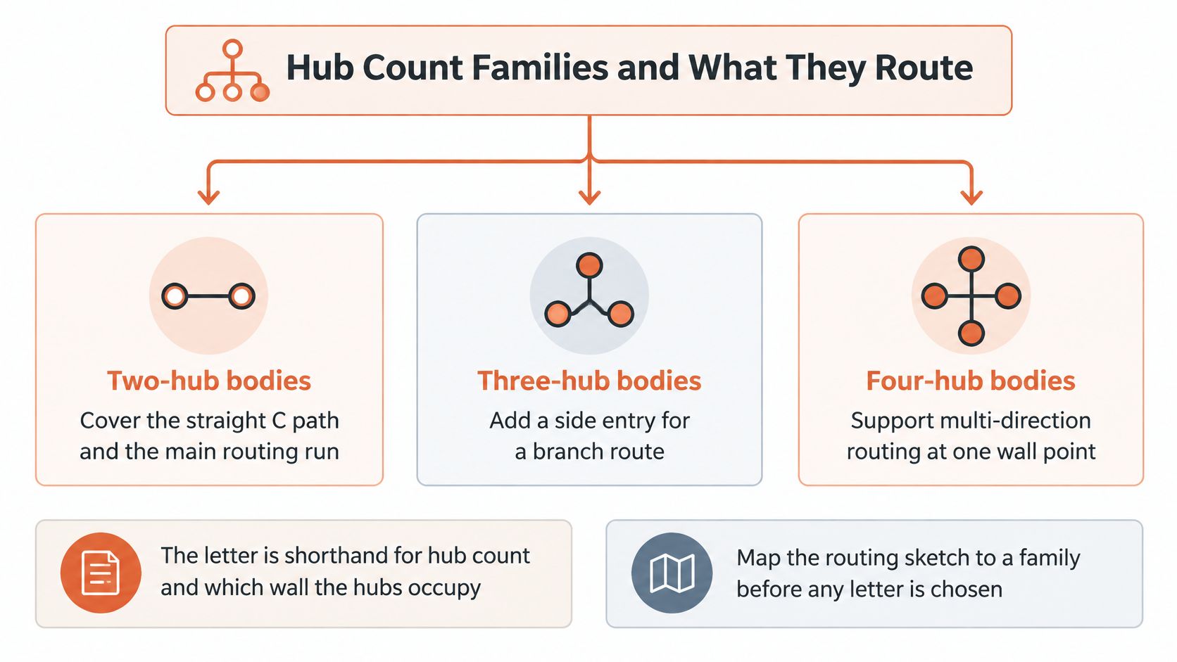
Hub Count Families and What They Route
Map the raceway sketch to a hub-count family before selecting a catalog item. The letter is shorthand for hub count and which wall the hubs occupy.
The family layout makes that first decision easier.
Match the family to the raceway schedule
The IAEI guide to conduit bodies groups straight, LB, LL, and LR bodies as two-hub configurations, Type T as three-hub bodies, and Type X as four-hub bodies; it also notes that hubs may have the same or different sizes where permitted.
Main routing run: Select the straight or turning family from the required continuation, not from whichever body is stocked.
Branch connection: Check the branch against the raceway schedule, including its destination and connection style.
Crossing runs: Reserve an X for a designed intersection using its hubs. Otherwise, a T or an appropriately selected box may produce a cleaner installation.
An unused hub isn't a spare knockout to leave open. If the design includes an unused opening, specify an identified closure suitable for the body and location.
Same-size hubs and listed reducing-hub configurations also need different purchasing descriptions. Confirm that the product permits the intended trade-size transition rather than assembling an undocumented substitute.
The letter belongs on the BOM because replacing LB with LL changes wall clearance, exit direction, and pulling geometry. A routing demonstration can help the buyer and installer compare the same orientation.
Field Examples for Each Letter
Use the cover-facing convention when walking these scenarios. Draw the cover as well as the conduit centerlines; a centerline-only sketch can hide the very obstruction that makes a fitting unusable.
Type C across a mechanical room
Say a straight 2-inch RMC run crosses a mechanical room between long sweeps and needs a covered pull point. A C body keeps the raceway in line while its cover faces the aisle, where the crew can guide conductors and inspect the interior.
Substituting an angle body doesn't provide equivalent access. It introduces an unnecessary turn and can force an offset that consumes the space intended for maintenance. Rotating the C cover toward the wall defeats the reason for installing it.
Type LB into a control panel
An EMT run follows a block wall and turns into the back of a control panel. An LB can keep the cover on the open wall face while the continuation leaves through the back toward the enclosure, provided the selected body and connections suit the EMT system.
An LL or LR substitution would send the continuation along the wall instead. Trying to recover the panel entry by rotating that fitting may put the cover against masonry. Compare the access requirement with the routing options discussed in this guide to a 90-degree conduit elbow, rather than treating every turning fitting as interchangeable.
Type LL along an equipment pad
Standing at the cover, the continuation needs to leave left along an equipment pad. An LL places that exit where the route needs it while keeping the access opening toward the service side.
An LR in the same location points toward the equipment instead. The crew may be able to add a field offset, but that workaround adds connections and changes the planned pulling route. Correct the body selection before fabricating the adjoining raceway.
Type LR beside a doorway
On the opposite side of a doorway, the continuation must leave right to clear the opening. An LR can place the hub away from the door swing while preserving access from the corridor or service aisle.
A left exit can land the hub or adjoining conduit in the door's travel. Check the actual door swing and trim, not just the rough opening. Moving the fitting after the conductors are installed is a much larger task than correcting the takeoff.
Type T feeding a local disconnect
A branch leaves a main rigid run for a local disconnect. Position the T so the crew can reach the branch pull and guide the conductors instead of dragging them blindly around an inside corner.
Rotating the body merely to simplify conduit alignment can move its cover out of reach. Also distinguish a raceway branch from an electrical tap: the routing arrangement doesn't establish permission to make a connection inside the body.
Type X at a designed intersection
Say crossing runs meet in an accessible ceiling service space and every hub is part of the design. An X can provide the intended intersection without piecing together an improvised collection of turning bodies.
It's a poor default for a branch that doesn't need the full cross configuration. A rotated or poorly located X can leave the cover above fixed equipment, and its additional openings don't resolve conductor-routing or circuit-separation requirements.
A fitting that saves conduit work but prevents the next conductor pull isn't a useful substitution.
Specify beyond the letter
The ABB conduit-body dimensional sheet shows that body length and internal volume change with trade size and configuration. The letter alone therefore isn't a purchasing description.
Send the dimension sheet with the proposed item, especially where equipment is already installed. Material, gasket construction, and listing compatibility require their own review rather than an assumption based on the shape.
Cover Access After the Wall Is Closed
LB versus LL versus LR isn't finished when the turn direction is correct. The selection has to preserve service access after the building and equipment installation are complete, not just while the wall is open.
Use the drawing review and field walkdown to evaluate the same conditions. A markup that shows the cover face is more useful than a note saying “provide accessible fitting.”
This access-focused selection sequence keeps the final installation in view.
Walk the installed condition
Mark the required turn. Trace the incoming run, continuation, and any branch on the raceway sketch. Identify the viewing direction before calling out the letter.
Place the cover on the lasting open face. Include wall finishes, equipment cabinets, insulation, guards, and adjacent piping. Empty space during rough-in may not remain empty.
Test removal access. Check that a hand and screwdriver can reach the fasteners and that the cover can lift away without moving other gear. Leave room to handle conductors, not merely loosen a screw.
Match the exposure. Select the body, cover, and gasket assembly for wet, washdown, outdoor, or corrosive conditions. Adding a gasket to an unsuitable assembly isn't a substitute for the required identification.
Verify raceway support. Show support near the body and at the intervals applicable to the wiring method. Don't leave the hubs carrying an unsupported run.
Confirm metallic-system bonding. Verify continuity through the applicable listed hubs, locknuts, or bonding means. A painted joint isn't a bonding plan.
EC&M's guidance on metal-conduit requirements explains that raceways must permit conductor installation and removal without insulation damage and must be supported near conduit bodies and at prescribed intervals. Check the adopted code and the actual wiring method when determining those requirements.
Resolve the alcove before buying the fitting
Consider a panel alcove where an LR matches the drawn turn but leaves the cover facing a hypothetical 2-inch gap beside a transformer. The outline fits, yet a technician can't realistically remove the cover and guide a conductor through that space.
If the adjoining raceway can be rerouted, an LB with its cover toward the aisle may resolve the access problem. That change needs a coordinated sketch showing the revised entry and continuation, not a handwritten instruction to substitute letters.
Make this check before adjoining runs are cut and threaded. Otherwise, fixing the cover orientation may require replacing fabricated conduit, relocating supports, and revising the enclosure entry.
Walkdown check: Evaluate the fitting from the position where a technician will actually remove the cover.
Access review and pull-space review answer different questions. A reachable opening doesn't prove adequate internal geometry, and adequate internal geometry doesn't make a blocked cover serviceable.
Pull Space and Raceway Fill Limits
Separate ordinary bodies from reduced-dimension bodies before approving a compact fitting. Hub size alone doesn't establish whether the actual conductors can be pulled through it without damage.
The UL 514B document preview describes the six-times angle-pull spacing, eight-times straight-body length, internal-area provisions, and listed reduced-dimension conditions summarized below. Apply these checks within their applicable code and product scope, not as a complete sizing method for every arrangement.
Pull-space and fill limits for conduit bodies
Check
Applies to
Minimum or limit
Exception
Entry to opposite wall
Angle and U pulls, including LB, LL, LR, and T
Six times the trade size of the largest raceway
Does not apply when the opposite wall is the removable cover
Body length
Body that does not change wiring direction
Eight times the trade size of the largest connected tubing or conduit
Listed area rules still apply
Internal cross section
Listed conduit bodies
Minimum area based on the largest connected raceway under UL 514B
Use the listed product, not a field guess
Reduced-dimension body
Compact bodies below ordinary spacing
Manufacturer must mark maximum conductor size and quantity
Design must pass a wire-pull test with no insulation damage
Conductor fill
Conductors in the connected raceway
Stay within fill allowed for that complete conduit or tubing system
A larger body is not an unrestricted expansion chamber
Understand what the opposite wall means
The cover exception is significant because it changes which internal measurement controls. Don't measure blindly across a catalog outline without locating the entry and the actual opposite surface.
For a hypothetical application of the rule, a 2-inch angle entry requires 12 inches to the opposite wall when that wall isn't the removable cover, using the spacing relationship in the cited document. That illustration isn't permission to ignore other applicable arrangement, conductor, or listing requirements.
A compact body may be acceptable under its listing even though it doesn't meet ordinary spacing. The manufacturer's conductor markings and applicable instructions establish that route to acceptance; an installer's ability to force a bundle through the opening does not.
Review the actual conductor combination
Approve a reduced-dimension body against the conductor schedule, not an informal statement that it “takes large wire.”
Identify the conductors. Record quantity, size, insulation type, and the intended pull path through the body.
Read the marking. Compare the actual combination with the manufacturer's permitted conductor size and quantity.
Check pulling instructions. Use the specified pulling lubricant when required and verify compatibility with the conductor insulation.
Inspect the opening. Confirm that the installed cover can be removed and that conductors can be guided without scraping edges.
OSHA's wiring-method requirements keep allowable cable fill within the limits for the complete conduit or tubing system. Extra space inside the body isn't an unrestricted expansion chamber for an overfilled raceway.
For larger feeder work, a 4-inch conduit selection review should therefore include the connecting fittings and conductor schedule, not just the straight raceway. Splices, terminations, and devices introduce a separate enclosure-volume question that a successful pull-space check doesn't answer.
Splices Terminations and Marked Volume
A conduit body isn't necessarily limited to pulling access, but permission to splice is conditional. Electrical Contractor's NEC commentary-change-part-9) explains that a body containing splices or terminations needs its cubic-inch volume marking and an applicable fill calculation.
An unmarked body isn't an ordinary junction box just because its cover comes off. Verify a durable manufacturer volume marking, the product's permitted use, and sufficient calculated volume before adding a splice, termination, or device.
Check a proposed retrofit
Say a crew wants to land a tap and terminal block inside an existing LB to avoid installing another enclosure. That proposal needs a documented review, not a visual judgment that the components appear to fit.
Read the marking. Record the usable marked capacity and identify the body and cover assembly.
Calculate the contents. Account for conductors, splices, and devices using the applicable enclosure-volume rules. Include equipment-grounding and bonding conductors when those rules require them.
Verify the intended use. Confirm that the listing and instructions permit the proposed termination arrangement.
Reject an unsuitable body. If the capacity is unmarked, insufficient, or inconsistent with the intended use, select an appropriate enclosure.
Keep raceway conductor fill separate from the body's enclosure-volume calculation. Neither calculation replaces the other.
Large-conductor retrofits and control modifications deserve particular scrutiny because terminal hardware can consume working space quickly. Verify the access wording and volume provisions against the NEC edition enforced by the authority having jurisdiction, then confirm the manufacturer's listing and markings before approval.
Listings Materials and Standards Crosswalk
Use standards to answer specific selection questions. This crosswalk isn't a substitute for the adopted code, the product listing, manufacturer instructions, or project engineering requirements.
The ANSI/NEMA FB 1 standards listing identifies performance expectations for fittings, cast-metal boxes, and conduit bodies used with the covered raceway and cable systems under NFPA 70. Keep that performance scope distinct from the product-listing and installation questions.
Match the document to the review
Standards that govern conduit body selection
Document
Question it answers
Verify on the submittal
NEC (NFPA 70)
Access, support, undamaged conductor installation and removal, and volume when splices are present
Adopted edition and whether the body will contain splices or only a pull
UL 514B
Listing of bodies for EMT, IMC, RMC, liquidtight flexible conduit, and rigid PVC
Listing mark, raceway compatibility, and hub or thread type
ANSI/NEMA FB 1
Performance expectations for fittings, cast-metal boxes, and conduit bodies on those raceways
That the specified fitting is in scope for the raceway system
OSHA definition
Conduit body class, and exclusion of FS and FD boxes and larger cast or sheet-metal boxes
That the item is specified as a conduit body and not as a box
For the NEC review, identify the edition the authority having jurisdiction enforces. Don't place a generic compliance statement on the submittal without documenting the intended installation.
For the listing review, match the exact catalog item to the connected raceway. A manufacturer may offer similar-looking bodies with different connection systems, and a family name doesn't prove that every member suits every raceway.
Match materials and connections
Threaded malleable-iron or aluminum bodies are common choices for rigid metal conduit and intermediate metal conduit when the product is identified for that system. EMT bodies need the setscrew or compression connections they're listed to use; don't assume a threaded opening directly accepts EMT.
PVC bodies belong with compatible PVC conduit and the specified joining method. For metallic systems exposed to chemicals or persistent moisture, evaluate corrosion resistance across the complete assembly, including covers, fasteners, and connecting fittings.
Wet or outdoor exposure: Verify the assembled body, cover, gasket, and entries for the location.
Washdown service: Check suitability for the actual cleaning exposure rather than relying on a gasket's presence.
Corrosive service: Compare the materials with the process environment; a stainless-steel conduit system still needs compatible fittings and project-specific review.
Hazardous locations: Require equipment identified for the applicable location. An ordinary covered body doesn't establish that suitability.
Record the listing, raceway material, hub or thread type, cover and gasket construction, corrosion resistance, and location suitability in the procurement package. Include the dimension sheet as well: trade size doesn't establish the installed length or usable internal volume.
Call Out the Body on the Bill of Material
A useful conduit-body callout lets purchasing order the intended assembly without interpreting a field sketch. Keep it on the same line item as the raceway schedule reference so the buyer, reviewer, and installer work from a common specification.
Don't release an order described only as “LB to suit.” That leaves the supplier guessing about connections, material, cover, and whether the body will contain anything beyond through conductors.
Build a complete buying description
Body type: Identify C, LB, LL, LR, T, or X and reference the marked-up routing detail.
Hub configuration: State each hub's trade size and its threaded, setscrew, compression, or other specified connection style.
Raceway system: Identify the connected raceway so the proposed body and fittings can be checked together.
Body material: Name the required material and any project-specified finish or corrosion-resistance requirement.
Cover assembly: Include the cover, gasket, and required fastening arrangement. Clarify whether these arrive with the body or as separate items.
Intended wiring work: State whether the body is pull-only or will contain splices, terminations, or devices. Require the applicable volume marking and supporting calculation where needed.
Location identification: Document wet-location, corrosive-service, or hazardous-location requirements that apply.
Submittal documents: Request the listing information, dimensional drawing, conductor limitations, and installation instructions for the exact item offered.
A supplier can then flag a missing field before it becomes a field substitution. That is especially valuable when the specified configuration is difficult to obtain and the purchasing team is comparing available alternatives.
Review an alternate as an assembly
During a shortage, a matching letter isn't enough to establish an approved equal. Another manufacturer's body may change the installed length, hub style, cover projection, conductor allowance, or marked volume.
Compare those fields against the actual installation and record the reviewer's disposition. Preserve the routing letter unless the responsible designer approves a coordinated routing change; an alternate letter can send the raceway in the wrong direction even when the nominal size matches.
Release check: Approve the exact catalog item and assembly, not a promise that the replacement is “the same type.”
Before shipment, confirm that the cover faces the accessible side, support is addressed, and the pull fits either the applicable ordinary dimensions or the compact body's actual conductor marking. Don't accept proposed splices without the required marked volume and calculation.
Selecting conduit body types is ultimately a coordination task between routing, maintenance, and procurement. Send the raceway schedule and a sketch with the cover face marked when asking for availability or alternate review, rather than asking the buyer to guess a substitute letter.
ATEK Distribution offers conduit-body and related-fitting sourcing, BOM review, hard-to-source alternatives, manufacturer coordination, and listing or compliance documentation for industrial, facility, and government projects. Visit ATEK Distribution with your raceway schedule and marked-up routing sketch to request an availability check and support evaluating proposed alternatives.
You've got a machine that needs 240 V, a service that's delivering something closer to 208 V, and a plant manager who wants a number you can defend. That's the normal starting point for buck boost transformer sizing, and it's also where most sizing jobs go wrong. Picking the next catalog size above load kVA feels safe. It isn't, because the transformer has to work at the lowest voltage the plant sees, during motor starting, and across a supply that may not stay put. Work it as a voltage-envelope problem first and a kVA problem second, and the selection gets much easier to justify to an inspector, a specifier, or procurement.
Say a 10 kVA control panel commissions cleanly at 230 V on a mild morning, then trips on hot afternoons when the supply sags to 208 V. Nothing inside the panel changed. The source did. A buck boost transformer corrects a voltage ratio, usually connected as an autotransformer, so its nameplate kVA represents the correction component rather than the full load-through capacity. That distinction drives every decision that follows.
Every sizing job needs the same inputs before you open a catalog.
Measured source voltage: Record it at the point of connection, not from a drawing.
Required load voltage: Take it from the equipment nameplate or manufacturer data, with its tolerance.
Phase configuration: Confirm single-phase or three-phase and how the load is connected.
Load current: Use full-load amps, and note whether the load runs continuously.
Buck or boost percentage: Calculate the correction from measured to required voltage.
Three traps account for most bad selections. First, sizing to nameplate kVA without checking capacity at the reduced input voltage. Second, treating motor starting as a steady-state question. Third, assuming a transformer can fix voltage that changes with load, which is a different class of problem covered in a broader look at common power quality issues in industrial facilities.
You'll leave with a six-step procedure, an adjusted-kVA table, starting and derating checks, a comparison against other fixes, and a pre-order checklist you can put in front of an inspector or plant manager.
How to Size a Buck Boost Transformer in Six Steps
Start with measurements, not catalog tables. A catalog assumes you already know your source voltage, your load voltage, and your load current. On a live site, at least one of those is usually a guess until someone logs it.
Step 1 Log the Source Voltage
Measure at the point of connection across a full operating cycle. Capture minimum, nominal, and maximum readings, including peak production, shift changes, and the times of day when trips happen. One meter reading taken at 9 a.m. tells you almost nothing about a 3 p.m. sag.
Use a recording meter or a power quality logger if you have one. If you don't, take timed readings under light load and full load and write them down with the load condition next to each one. That log becomes the voltage envelope you'll size against.
Step 2 Pull the Required Load Voltage
Take the required voltage and its allowable tolerance from the equipment nameplate or the manufacturer's data sheet. Don't substitute a nominal system voltage. Equipment rated for one voltage class may tolerate a narrow band, and that band determines whether your corrected output is acceptable at both ends of the envelope.
Note the phase configuration and whether the load needs a neutral. Record those now, because they can rule out an autotransformer connection outright.
Step 3 Calculate the Correction
Buck or boost percentage = (target voltage - measured voltage) ÷ measured voltage × 100.
Say a 12 kVA load sits on a 208 V supply and needs 240 V. The correction is (240 - 208) ÷ 208 × 100, which is about 15.4% boost. Run that arithmetic at the minimum and maximum logged voltages too, not just at nominal.
Field rule: Size for the worst point in the envelope, then check that the opposite extreme doesn't push the load outside its allowable voltage range.
Step 4 Determine Load Current and Load kVA
Use nameplate full-load amps for load current. Then compute load kVA with the formula that matches your system.
Single-phase: kVA = V × I ÷ 1000
Three-phase: kVA = V × I × 1.732 ÷ 1000
Flag whether the load is continuous or intermittent. A load that runs for hours at full current stresses the unit thermally in a way a short-duty load doesn't, and that affects both selection and enclosure ventilation.
Step 5 Check Adjusted Capacity at the Lowest Input
This is the step people skip. The Eaton low-voltage dry-type buck-boost design guide documents the method as new kVA rating = actual output voltage ÷ rated input voltage × output kVA rating, with a 240 V input, 10 kVA output unit operated at an actual 220 V input giving an adjusted capacity of approximately 9.17 kVA.
Apply that formula at your lowest expected input voltage, not at nominal. Then select a rating that still covers load kVA at that low point with margin to spare. If it doesn't cover the load at the low point, the nameplate number is irrelevant.
Step 6 Verify the Installation Conditions
Before you finalize, check motor inrush, conductor ampacity, overcurrent protection, grounding, and neutral availability against the manufacturer's instructions for the specific unit. Confirm the applicable NEC articles with the project's engineer or inspector rather than relying on a general guide. Manufacturer instructions and the adopted code govern the connection, and neither a distributor nor a selection chart overrides them.
The most common error is simple. Someone picks the next nameplate size above load kVA at nominal voltage, and the unit ends up undersized at the low point the plant sees. Steps 1 and 5 exist to stop exactly that.
Tap Settings and Adjusted kVA Worked Examples
Nameplate kVA misleads because it's stated at rated input voltage. Run the unit below that voltage and usable capacity falls in proportion. The table below applies the design-method formula, adjusted kVA = actual input ÷ 240 V × 10 kVA, to a hypothetical 10 kVA unit rated 240 V input so you can see the reduction row by row.
Adjusted kVA for a 10 kVA buck boost unit rated 240 V input
Actual input voltage (V)
Adjusted kVA
Reduction vs. nameplate
240
10.00
0%
230
9.58
4.2%
220
9.17
8.3%
208
8.67
13.3%
200
8.33
16.7%
Reading the Table Against a Real Load
Look at the 208 V row. The unit yields about 8.67 kVA there. If your load is 9 kVA, you're already over capacity at that input, even though the nameplate says 10 kVA and the selection looked comfortable on paper. That's not a marginal miss. That's the difference between a unit that runs within rating and one that runs hot every afternoon.
The 230 V row shows the same effect in smaller form. You're down to 9.58 kVA, so a load sitting just under nameplate has almost no margin left for continuous duty, enclosure heat, or a further dip.
At 200 V you've lost roughly a sixth of nameplate capacity. If your logged minimum is anywhere near that level, sizing from nominal voltage will undersize the unit by a wide margin.
A Second Worked Example With Margin
Say you select a 12 kVA-rated unit fed from 220 V against a 240 V rating. Adjusted capacity is 12 × 220 ÷ 240, which gives about 11.0 kVA. Against a hypothetical 10 kVA load, that leaves roughly 10% margin at the low point. Whether that margin is enough depends on duty cycle, ambient conditions, and starting demands, but at least you're evaluating margin at the voltage that matters.
Now run the same load against a unit chosen only because its nameplate exceeded 10 kVA. At 208 V you'd be working with a much thinner cushion, and any additional sag eats it entirely. I would rather defend a slightly larger unit with documented margin at minimum input than explain a thermal failure later.
Choosing the Tap
Most units offer discrete taps that connect the input to the correction you need. Choose the tap nearest your measured supply that produces the target output, and confirm the connection on the manufacturer's wiring diagram for that exact unit. Tap designations aren't interchangeable between manufacturers or even between product lines.
If your supply swings across two taps, size and set the tap for the worst-case output, then check the other extreme. A tap that delivers correct voltage at minimum input may overvoltage the load at maximum input. Both ends of the envelope have to land inside the equipment's allowable range. If no single tap does that, you don't have a tap problem. You have a voltage stability problem, and a different fix applies.
Set the tap for the worst case, then prove the opposite extreme is still acceptable. Checking only one end is how overvoltage damage gets designed in.
This table applies the formula only. It doesn't replace nameplate values, tap connections, or rated voltages from the manufacturer. Use it to screen candidate sizes, then verify the final selection against the submittal and wiring diagram before you order.
Derating, Motor Starting and Voltage Envelope Checks
A motor that won't start doesn't care that your steady-state math was correct. Manufacturer guidance summarized in the Schneider Electric buck-boost FAQ notes that motor starting current can reach roughly five to seven times running current and that motor torque falls approximately with the square of voltage. Run the numbers on that second point. A 10% undervoltage at start leaves you with about 81% of rated torque, a loss of roughly 19%. For a loaded compressor or a pump starting against head pressure, that's often the difference between accelerating and sitting at locked rotor until protection operates.
Estimating Voltage Drop During Starting
Schneider Electric states that motor voltage drop can be estimated from locked-rotor current divided by transformer secondary full-load rating, multiplied by transformer impedance. Use that as your starting estimate, with locked-rotor current from the motor nameplate or manufacturer data rather than a multiple you guessed.
There's an apparent contradiction worth resolving. Buck boost autotransformers have low circuit impedance, so locked-rotor current doesn't necessarily create a large drop across the transformer itself. Both statements are true. The transformer is only one element in the circuit. Service impedance, feeder conductors, upstream overcurrent devices, contactors, and the starting method often dominate the actual sag at the motor terminals.
So check the weakest source and feeder case, not the strongest. That means minimum logged source voltage, the longest feeder run in the path, and any upstream equipment that adds impedance. A selection that works on a stiff service can fail at the end of a long run fed from a heavily loaded panel, which is why feeder origin matters as much as transformer size when you're evaluating something like a 100 amp three-phase panel as the source.
The Four-Line Worksheet
Write these four values down for every motor load. If you can't fill in a line, you don't have enough data to finalize the size.
Normal output voltage: Corrected voltage at running load and nominal input.
Worst-case starting voltage: Voltage at the motor during start at minimum input.
Recovery voltage: Voltage once the motor reaches speed and current falls.
Allowable motor undervoltage: The limit from the motor or equipment manufacturer.
Say a worksheet shows normal output of 240 V, worst-case starting voltage of 216 V, recovery to 228 V, and an allowable undervoltage of 10%. The starting dip sits exactly at the limit. That leaves no margin for a weaker utility day or an added load on the same feeder, so don't accept the transformer size yet. Review the source and feeder case, or revisit the starter, before you sign off.
Reduced-voltage starters and variable-frequency drives change inrush substantially, so they change the worksheet result. A drive that ramps the motor may remove the starting problem entirely. It can also introduce harmonic and compatibility questions that belong with the drive and transformer manufacturers, not with a generic sizing rule.
Derating Conditions
Usable capacity also falls with ambient temperature, enclosure ventilation, altitude, continuous loading, and harmonic-producing loads. Don't apply a generic percentage you found in a forum. The manufacturer's derating data for the specific unit governs, and it should be part of the submittal package.
Say a remote pump station runs unattended and a failed start means a truck roll, a drained wet well, or a process shutdown. There, the cost of a nuisance trip dwarfs the cost difference between transformer sizes. I'd spend the engineering time on the worksheet and the derating check, because that's where the failure originates.
When a Buck Boost Transformer Is the Wrong Fix
A buck boost transformer doesn't regulate. The AutomationDirect buck-boost transformer manual states that if input voltage changes with load, output voltage changes at the same rate, and it recommends a regulator when the load can't tolerate that variation. That one characteristic rules out a buck boost unit for a large share of the voltage complaints that reach a facilities desk.
A site that reads 208 V at light load and 195 V at peak demand shows why. Set the ratio to correct the 195 V reading and the output runs hot at light load. Set it for 208 V and the peak-demand dip passes straight through. You can be correct at one point in the envelope, never both. So build the voltage envelope first, from minimum, nominal, and maximum logged readings. If that envelope is wider than the equipment tolerance, stop sizing transformers and change approach.
Which fix matches which voltage problem
Condition
Likely fix
Limit to check
Persistent nominal mismatch at steady load
Buck boost autotransformer
Input swings pass through to output at the same rate
Input varies with load and the equipment cannot tolerate it
Tap-changing voltage regulator
Regulator sizing and controls must be confirmed with the manufacturer
Voltage drop caused by conductors or source impedance
Feeder or service redesign
Higher cost and longer lead time; requires engineering study
Disturbances, sags, or harmonics rather than magnitude error
Power-quality equipment
Does not correct a voltage ratio; a different problem entirely
Check the neutral question early. An autotransformer cannot create a neutral where none exists, so a load that needs one needs a different solution entirely. Then look at phase balance, shared feeders, and harmonic-producing loads, all of which can produce symptoms that look like a simple voltage mismatch.
Low voltage in a building often traces back to wiring and connection faults rather than the utility. The resource on Palm Beach County wiring and voltage issues from Lighthouse Energy Services is a useful plain-language rundown of those upstream causes, worth working through before you specify equipment for a drop the service didn't cause.
Load growth changes the answer over time. Adding EV chargers, heat pumps, solar inverters, and battery systems alters load profiles and can widen the envelope you measured this year. A buck boost ratio sized for today's profile can sit wrong inside next year's envelope, so size for the profile the site is heading toward.
One capacity point needs care. Some manufacturers publish autotransformer application ratings well above the unit's nameplate kVA. A published rating like that still carries conductor, protection, thermal, and fault-duty requirements, and the project engineer's review decides whether the application stands. Confirm it against the manufacturer's data for the specific unit before you rely on the number.
The decision test itself is simple. When a time-series log shows the envelope exceeding equipment tolerance, move to a regulator or a feeder study. A larger buck boost unit won't fix a moving input.
Efficiency, Documents and Pre-Order Checks
Efficiency gives you a benchmark for losses and heat, not a promise about your installation. The Bonneville Power Administration technical report on dry-type transformers summarizes the U.S. Department of Energy 2016 standards for low-voltage dry-type distribution transformers as effective January 1, 2016, with single-phase efficiencies from 97.70% at 15 kVA to 98.90% at 333 kVA and three-phase efficiencies from 97.89% at 15 kVA to 99.28% at 1,000 kVA.
DOE 2016 minimum efficiency reference values for selected ratings
Rating (kVA)
Phase
Minimum efficiency
15
Single-phase
97.70%
15
Three-phase
97.89%
333
Single-phase
98.90%
1,000
Three-phase
99.28%
Confirm whether your chosen unit falls within DOE scope before you rely on the benchmark. These are test-condition values for the transformer itself, so treat them as a reference point rather than a prediction of how a particular buck boost installation will perform under your load profile and tap setting.
The loss arithmetic still matters for thermal planning. Take the lowest value in the table: at 97.89% efficiency, roughly 2.11% of transferred power becomes heat under the applicable test condition. For a 15 kVA unit, that works out to about 0.32 kW of loss. That heat lands in your enclosure and your electrical room, so fold it into the ventilation and ambient assumptions you already used for derating.
Documents to Request Before Purchase
Nameplate and rating data: Confirms rated voltages, kVA, and phase for the exact unit.
Wiring diagram: Shows tap connections for buck and boost configurations.
Derating curve: States how capacity changes with your ambient and enclosure conditions.
Submittal sheets: Gives dimensions, enclosure type, and weights for coordination.
Listing or certification information: Whatever the manufacturer confirms for that model.
Origin and trade compliance statements: Verify Buy American or Trade Agreements Act statements directly with the manufacturer where a project requires them.
Pre-Order Checklist
Don't release a purchase order until you can fill in each line.
Recorded voltage envelope: Minimum, nominal, and maximum at the point of connection.
Required output voltage and tolerance: From equipment manufacturer data.
Buck or boost percentage and tap positions: Calculated at both envelope extremes.
Worst-case load kVA and adjusted kVA: Adjusted at minimum input, with margin stated.
Motor starting and recovery result: From the four-line worksheet.
Derating conditions: Ambient, altitude, enclosure, and load character.
Neutral availability: Confirmed, or an alternative solution selected.
Lead time and approved alternative: At least one, identified before you need it.
If you're comparing candidate ratings while you build that worksheet, browsing a 25 kVA transformers category is a practical way to see what enclosure and configuration options exist at a given size before you commit to a submittal. Send the completed worksheet with your request. A sourcing team can then verify rating and tap selection against the manufacturer submittal, flag hard-to-source configurations, line up approved alternatives if lead time slips, and coordinate the compliance documents your project file needs.
Send your completed voltage envelope, load kVA, and adjusted kVA worksheet to ATEK Distribution and we'll review the bill of material, verify rating and tap selection against manufacturer submittals, and identify approved alternatives if your first-choice unit carries a long lead time. You'll get sourcing and compliance documentation support from a team that keeps mission-critical electrical projects moving, so your buck boost transformer sizing holds up in the field and in the project file.
“2 inch” is a trade size, not a measured bore. Schedule 40 PVC has a 2.375-inch outside diameter and an approximate 2.067-inch inside diameter. Schedule 80 retains the same outside diameter but has a thicker wall, reducing the space available for conductors.
A purchase order that lists only “2 inch” leaves key requirements unspecified. During shortages, contractors may consider substitutes, but a matching trade-size label does not guarantee the same fill capacity, support requirements, raceway type, or listing accepted for the installation.
Check each line item against four requirements: trade size, schedule or wall thickness, raceway type, and the applicable conduit fill rule. Confirm the conductor count and raceway dimensions before approving a substitution. The pathway sizing reference used in installer training explains how conduit sizing and fill relate to the usable space inside a raceway.
These details affect both procurement and installation. A conduit that matches the order's nominal size may still leave too little room for the planned conductors or fail to meet the requirements for its location. Specify the full configuration so the delivered raceway matches the design and can be checked before it reaches the job site.
A 2-inch conduit line is incomplete without a raceway type and wall specification. The nominal trade size identifies the product, but outside diameter governs fitting compatibility, while inside diameter determines the space available for conductors. Those dimensions are not interchangeable across materials or wall types.
For rigid PVC, the UL 651 product standard listing gives Schedule 40 2-inch conduit an outside diameter of 2.375 inches, a minimum wall of about 0.154 inches, and an approximate inside diameter of 2.067 inches. Schedule 80 has the same outside diameter, but its minimum wall is about 0.218 inches and its average inside diameter is about 1.881 inches. The smaller bore reduces usable conductor space even though the nominal size and outside diameter stay the same.
Weight changes with wall thickness. A Seattle City Light conduit data sheet lists Schedule 40 at about 0.70 pounds per foot and Schedule 80 at about 0.96 pounds per foot. A 10-foot Schedule 40 length therefore weighs about 7 pounds before fittings. Schedule 40 is commonly supplied in 10-foot or 20-foot lengths. For rigid PVC installations, the governing NEC article is Article 352.
Metallic products illustrate why the label alone is not enough. Robroy Stainless lists 2-inch 304 stainless rigid conduit at 3.73 pounds per foot and a width of 2.375 inches. Its liquid-tight flexible metallic conduit with a stainless core measures 2.340 to 2.375 inches across and weighs 136 pounds per 100 feet, or 1.36 pounds per foot. The flexible product's outside dimension and weight do not supply its inside diameter, so use its manufacturer's dimensional data for fill calculations.
Type
Outside diameter (in)
Inside diameter (in)
Wall or minimum wall (in)
Weight (lb/ft)
Schedule 40 PVC
2.375
about 2.067
0.154 minimum
0.70
Schedule 80 PVC
2.375
about 1.881
0.218 minimum
0.96
304 stainless rigid conduit
2.375 (width)
Manufacturer's data required
Manufacturer's data required
3.73
Liquid-tight flexible metallic, stainless core
2.340 to 2.375
Manufacturer's data required
Manufacturer's data required
1.36
For EMT, RMC, IMC, and HDPE, take the inside diameter and weight from the specific manufacturer's data sheet. Do not substitute PVC dimensions or weights for another raceway type when checking fit, fill, or handling requirements.
Practical rule: Specify the material, schedule or wall type, and supplied length. A purchase order that says only “2 inch” leaves room for a substitution with a different bore, weight, or level of physical protection.
How Many Conductors Fit in 2-Inch Conduit
Fill is an area problem, not a trade-size problem. You add the cross-sectional area of each insulated conductor, then compare that sum with the portion of the raceway the adopted code allows. Insulation counts. A bare copper number from a catalog is the wrong input.
NEC Chapter 9, Table 1 sets the limits the Steel Tube Institute fill guide walks through: 53% for one conductor, 31% for two, and 40% for more than two. The 40% figure is the one most power, control, and instrumentation runs use in the field.
Conductors in raceway
Maximum fill of internal area
Typical application
One conductor
53%
Single conductor runs
Two conductors
31%
Two-conductor runs
Three or more conductors
40%
Multi-conductor power, control, and instrumentation runs
Four steps that keep the BOM honest
Confirm the raceway and its internal area. Use NEC Chapter 9, Table 4 for the exact article, then check the maker's sheet. A rigid PVC dimensional sheet from Westlake Pipe puts Schedule 40 near an internal diameter of 2.067 inches, about 3.35 square inches, and Schedule 80 near 1.881 inches, about 2.78 square inches. EMT is close to Schedule 40 but not identical. Do not paste a PVC area onto an EMT line without opening Table 4 for Article 358.
Apply the fill percentage to that area. At 40%, Schedule 40 screens at about 1.34 square inches and Schedule 80 at about 1.11 square inches. These are screening numbers. They are not a substitute for the adopted Chapter 9 tables or a local amendment.
Add insulated conductor areas from Chapter 9, Table 5. Use the insulation type on the drawing, THHN, THWN, XHHW, or whatever is specified. Do not substitute a different insulation because the copper size matches.
Compare and move up a trade size if the sum exceeds the permitted area. Also check pulling tension, sidewall pressure, bend count, and box entries. A legal fill can still be a bad pull.
A worked example, then the schedule trap
The Steel Tube Institute's example is the cleanest way to see the method. Three THWN conductors with a combined area of 0.4171 square inches need a raceway whose 40% area is at least that large. The table comparison lands on 1-1/4-inch EMT as the minimum, not 1 inch. The same arithmetic on a crowded feeder tells you whether 2 inch is enough, or whether you should step to something like 4 inch conduit when the bundle, the bends, and the pull length all stack up.
A 2-inch Schedule 80 run has less permitted area than a 2-inch Schedule 40 run with the same wire. If someone "upgrades" the schedule for abuse protection after the fill was approved, rerun steps 1 through 4. The wire package that passed can fail without a single conductor changing.
Edge cases that rewrite the answer
Short nipples can use a different allowance than a full run. Cable assemblies are not the same calculation as individual conductors. Equipment grounding conductors count toward fill. Multi-conductor cables, derating, and jam ratio sit beside the percentage, not instead of it. Approve the raceway article and the manufacturer data before the 2 inch conduit line on the BOM is released.
Ampacity Adjustments When Conduit Carries Many Conductors
A raceway size does not assign ampacity. Heat does. When several current-carrying conductors share a 2 inch conduit, each one runs warmer than it would alone, and the code cuts the allowable current before you ever look at the breaker.
Count-based adjustment
NEC 310.15(C)(1) applies an adjustment factor to the base ampacity once you have four or more current-carrying conductors. Confirm the table in the edition your authority having jurisdiction has adopted. The factors practitioners use from that rule are:
Current-carrying conductors
Adjustment factor
4 to 6
80%
7 to 9
70%
10 to 20
50%
21 to 30
45%
31 to 40
40%
41 and above
35%
Say a feeder or a control bundle puts twelve current-carrying conductors in the raceway. That count sits in the 10-to-20 band, so the factor is 50% of each conductor's base ampacity. Apply that cut first. A conductor that looked fine at its table ampacity may need the next size up, or the bundle may need to be split across two raceways.
Temperature is a second multiplier
Ambient correction under NEC 310.15(B) is separate. A hot mechanical room, a rooftop, or a run beside process piping does not get absorbed into the count factor. You multiply the base ampacity by the count factor and by the temperature correction for the insulation and the ambient. Order matters less than doing both. Skipping either one overstates what the wire can carry.
Neutrals that carry only unbalanced current, and equipment grounding conductors, are often excluded from the current-carrying count. A neutral on a nonlinear load may not be. Those exceptions live in the adopted text and in local amendments, so count conductors from the one-line, not from memory of a prior job.
A conduit can pass the fill limit and still force a derating that the panel schedule never allowed for. Run fill and ampacity in the same review, on the same conductor list.
EMT, PVC, RMC, IMC and HDPE Compared for 2-Inch Runs
Wall thickness and the way the joint is made decide weight, labor, and where the raceway belongs. Trade size does not. Pick the article that matches the room, the soil, or the abuse, then size the bore.
Type
Wall and joining
Best fit for 2-inch
Main limitation
EMT
Thin-wall steel or aluminum, setscrew or compression fittings
Interior commercial and light-industrial runs
Limited physical protection
Rigid PVC
Nonmetallic, solvent-cement joints
Underground and corrosive areas
Needs protection and expansion planning above ground
RMC
Thick-wall, threaded
Outdoor and high-abuse industrial areas
Heaviest option; requires power bending
IMC
Thinner than RMC, threaded
Where RMC protection is needed with less weight
Threading required
HDPE
Nonmetallic, listed joining method
Underground and directional bore
Not a fit for exposed runs without added protection
Liquid-tight flexible metallic
Flexible metal with listed fittings
Motor and equipment connections
Not a rigid raceway
EMT (Article 358) is the fast interior choice. Setscrew fittings are common in dry commercial work. Compression fittings earn their place where the listing or the spec calls for them. It is a poor pick where forklifts, weather, or corrosive washdown can reach the tube.
Rigid PVC (Article 352) solvent-cements and shrugs off a lot of chemical exposure underground. Above grade it needs physical protection where damage is likely, plus expansion fittings when the run sees a real temperature swing. It is not a grounding path.
RMC (Article 344) is the heavy, threaded answer for outdoor and high-abuse industrial areas. You will want a power bender or factory elbows at this size. IMC (Article 342) is also threaded and is used where RMC is permitted, with less weight to hang and to pull. A side-by-side of those metal systems is worth reading before you default to the heavier stick: EMT versus rigid conduit.
HDPE (Article 353) belongs in trench and directional bore, joined by the method the listing names. Do not leave it exposed and call it equivalent to RMC. Liquid-tight flexible metallic conduit (Article 350) is a whip to a motor or a skid, not a 200-foot feeder.
Two jobs, two answers
A 200-foot indoor feeder in a dry warehouse, with limited physical damage and a straight rack, is an EMT job unless the spec says otherwise. Labor stays down, and compression or setscrew couplings match the listing. The same nominal size as a riser on an exterior pole is a different product. There you want RMC, IMC, or Schedule 80 where the code requires a damage-resistant raceway, threaded or listed for that exposure, with a transition fitting back to whatever is buried.
The table is a starting point. The controlling pair is the code article and the environment on that segment of the route.
Where 2-Inch Conduit Is Used and What Limits Its Location
A 2-inch trade-size raceway can serve a feeder, underground lateral, pole riser, or large control and instrumentation run. The order line is incomplete until it identifies the raceway type and the conditions along the route. Where the run ends at metering equipment, coordinate the raceway route with the gear layout. This guide to planning electricity sub meter installation can help frame that coordination.
What OSHA requires on a construction site
OSHA's construction wiring-method requirements are in the construction standard for wiring systems. For pole risers, the standard specifies suitable raceway protection for conductors emerging from the ground. RMC, IMC, PVC Schedule 80, or an equivalent must extend from the ground line to at least 8 feet above finished grade, and metallic enclosures must be grounded. Check the applicable standard and adopted code for the installation; do not treat a general-purpose raceway choice as sufficient for every location.
One route, three products
Consider a lateral leaving a pad-mount, crossing a yard, rising on a wall, and entering a switchboard room. The nominal trade size may remain 2 inches, but the product should change where exposure changes.
Underground: PVC suits a buried section where soil and corrosives can affect bare steel. Confirm the burial method against Article 352 and the burial table in the adopted code.
At the riser: Use Schedule 80, RMC, or IMC where physical damage is a concern, and carry the raceway to the height the applicable rule requires.
Inside the building: EMT or another permitted metal raceway may suit the interior section. Use a listed transition, and maintain the required bonding path across the change from PVC.
Classified locations impose a separate selection requirement. The equipment and wiring method must be approved for the specific classification, or use the applicable intrinsically safe approach. Match fittings, seals, and approval markings to the area. A fitting marked 2 inches is not automatically approved for a classified location.
The authority having jurisdiction, adopted code, and environmental classification govern the final selection. Specify the raceway type for each segment, not just “2-inch conduit,” so substitutions do not erase the protection the route requires.
Fittings, Couplings and Expansion Hardware for 2-Inch Runs
The fitting follows the conduit, not the other way around. A 2-inch coupling from the wrong system is a mismatch even when the number stamped on it looks right.
Match the joint to the material
Threaded RMC and IMC use threaded couplings. Terminations use locknuts and bonding bushings where the bonding path requires them. Do not mix a thread standard the hub was not cut for.
EMT uses setscrew or compression couplings and connectors the listing allows for that installation. A dry interior setscrew coupling is the wrong part in a wet or concrete-tight location.
Rigid PVC uses solvent-cement couplings, primer where the cement system requires it, and a listed transition fitting where plastic meets metal. That adapter is a BOM line, not a field invention.
HDPE uses the joining method listed for that product. If the submittal says fusion, a mechanical coupling from another system is not a silent substitute.
Expansion fittings belong on PVC that sees a significant temperature change, placed the way the manufacturer and the article describe. Guessing the gap at one end of a long roof run is how couplings crack in the first summer.
Hardware the pull will demand
Conduit bodies, LB, LR, LL, and T styles, plus pull boxes, are sized for the conductors and the direction change. Count them in the takeoff. Adding a body after the rack is hung usually means a coupling in a place you did not want one.
Grounding and bonding hardware on metal raceways has to satisfy the article, not just "touch metal." In a hazardous location, sealing fittings and the approved hubs go on the order with the conduit. Before release, confirm each fitting's listing matches the conduit type and the location, and that the size stays 2 inch unless a reducer appears on the drawing.
Substituting a fitting from a different manufacturer is a common way to get mismatched threads or a joint the listing does not cover. Check it against that maker's data before the release, not after the first failed pull.
Bend Limits, Threaded Joints and Pull Planning
Routing is limited by the total bend between pull points, not by how many elbows the CAD layer shows. A public conduit specification written to NEC requirements, the ADOT electrical conduit specification, states that bends between pull points must not exceed 360 degrees. Bends also have to avoid crimping or flattening, and they have to use no less than the applicable NEC radius. Field bends should use the longest practical radius.
Two 90-degree bends plus one 180-degree sweep already consume the full 360 degrees. The next turn needs a pull box or a revised route. On large conductors in a 2 inch conduit, that limit is really about pulling tension and sidewall pressure. A legal-looking route can still skin insulation at the throat of a tight elbow. The same geometry shows up on device runs. Crews who avoid common CCTV installation mistakes already know that a camera whip full of elbows becomes a pull you cannot finish without a box.
Install in this order
Plan the route and add the degrees between pull points. If the sum is over the limit, move a box now, while it is still a sketch.
Cut PVC square and deburr every end. A knife edge inside a 2-inch stick will cut the jacket on the first pull.
Bend to the bender chart for that material, using the longest practical radius. A factory long-radius elbow beats a field bend when the chart radius is hard to hit. Keep a 90 degree elbow conduit in the takeoff when the turn is structural, not a tweak.
Make RMC and IMC threaded joints wrench-tight. In hazardous, classified locations, OSHA 1926.407 requires threaded conduit and wrench-tight joints, and a bonding jumper where making the joint tight is impractical. Outside those locations, bond the way the applicable NEC article and the fitting instructions require.
Support the raceway to the spacing in its article. A 2-inch stick sags differently in PVC than in RMC. Use the article you installed.
Put bodies, pull boxes, and long-radius elbows on the material list before the pull. They are not field substitutions after the truck leaves.
The failures that show up at inspection are predictable. Sidewall pressure on large conductors, insulation cut at a flattened bend, and a loose threaded joint in a classified area. Each one is cheaper to prevent on the takeoff than to open up after the wire is in.
Specifying, Verifying and Ordering 2-Inch Conduit
An order line that survives substitution names more than a diameter. Write nominal size, material, schedule or wall (Schedule 40 or 80 PVC, EMT, RMC, IMC, or HDPE), length (10-foot or 20-foot where that applies), listing and code article, fitting type, coating or finish, and whether a submittal is required. "2 inch conduit, gray" is how the wrong stick arrives.
A price benchmark, not a quote
In 2025, BuildGents unit-price data reported a median public-bid price of $31.00 per linear foot for 2-inch electrical conduit. The middle half of those bids ran from $20.00 to $48.75. That spread is bid scope and region, installed work rather than a stick price at a counter. Use it to sanity-check an estimate. Do not paste it into a purchase order.
Check the package before it ships
Before the BOM is released, confirm each of these. They catch the swaps that look harmless on a packing list.
Material and schedule are named on both the spec and the quote, not implied by color or by a photo.
Inside diameter, not the trade size, is the fill input, and the raceway article matches Table 4.
Fill and ampacity adjustment are both checked against the adopted NEC edition and any local amendment.
Total bend between pull points stays inside the limit, with boxes already on the list.
The raceway matches the location, including any hazardous-location approval, seals, and markings.
Fittings, bodies, supports, and pull boxes are in the takeoff at the same size, unless a reducer is drawn.
Set screw couplings and equipment lugs still have to be tightened to the values the listing expects. A short buyer-side read on how to compare torque screwdriver features keeps that last step from becoming "snug by feel."
When a substitute is offered
Do not accept "equivalent 2 inch" on the trade size alone. Review inside diameter and the fill effect, the listing and code article, fittings, grounding and bonding, bend radius, environmental rating, country-of-origin documentation, and submittal approval. If any one of those moves, the rest of the package has to be rerun.
ATEK Distribution can compare that BOM with the specification, flag approved alternates when a specified product is delayed, and collect the compliance documentation the project needs. Send the spec, the conductor schedule, and the BOM for a technical review. Availability and lead times get confirmed on that request. They are not promised from a catalog page.
ATEK Distribution helps contractors, engineers, and procurement teams source 2 inch conduit, fittings, and the raceway hardware that has to match the spec, including hard-to-find alternates and the paperwork that goes with them. If a 2-inch line on your BOM is short on schedule, listing, or fittings, send it over before the substitution hits the site. Start with ATEK Distribution and ask for a project-specific availability check.