
Power issues accounted for 45% of impactful data-center outages in the Uptime Institute's 2025 Global Data Center Survey, down from 54% in 2024. That's a useful warning for anyone specifying redundant power supplies: buying additional hardware isn't the same as removing the failure path. The meaningful test is whether the load keeps running when the defined component, feed, or supply system fails.
Table of Contents
- Why Redundant Power Supplies Matter Before the Panel Is Drawn
- N+1, 2N, A/B Feeds and Parallel DC
- Availability Tiers and What the Downtime Figures Mean
- Decoupling and Sizing 24 VDC Redundant Supplies
- Testing and Monitoring a Redundant Supply System
- Failures That Duplicate Hardware Cannot Prevent
- Choosing the Right Topology for Your Load
Why Redundant Power Supplies Matter Before the Panel Is Drawn
Within power-related IT-service outages, the same Uptime Institute survey identified UPS failures as the leading cause at 42%, followed by transfer-switch or utility failures at 36% and generator failures at 28%. Those findings concern data centers, not industrial control-panel failure rates, but the engineering lesson applies: redundant capacity doesn't eliminate shared dependencies.
A second supply won't protect a load if both supplies lose their common input. Shared batteries, controls, transfer equipment, and upstream distribution can defeat otherwise healthy equipment. Procurement therefore needs a functional requirement before it needs a manufacturer part number.
Define the failure before specifying the equipment
Redundant power supplies provide additional capacity and an arrangement that keeps the required load operating after a defined failure. The definition must name the boundary: a failed module, a lost feed, or the loss of an entire supply system.
Before fixing the BOM, answer these questions:
- Failure scope: Which specific event must the load survive, and which events remain outside the design?
- Surviving load: Must every connected device remain energized, or can the control system shed nonessential loads?
- Maintenance allowance: Can the process stop for replacement, or must technicians isolate equipment while the load continues operating?
These answers affect more than supply wattage. They determine distribution paths, isolation provisions, alarm wiring, access, and the replacement procedure.
Separate continuity from power conditioning
A UPS addresses a different set of operating conditions from a duplicated DC supply. HighFlow Energy's explanation of how an uninterruptible power supply works is a useful primer when deciding where stored-energy support belongs in the architecture.
Likewise, investigate power quality issues before treating repeated supply trips as evidence that another supply is needed. Voltage disturbances, unsuitable protection, and input conditions require their own corrective actions.
Design rule: Specify the failure the load must survive, not simply the number of supplies the cabinet must contain.
Topology follows from that failure scope. Availability targets, output decoupling, post-failure load calculations, and network dependencies then establish whether the proposed arrangement meets it.
N+1, 2N, A/B Feeds and Parallel DC
Redundancy topologies by failure scope and overhead
| Topology | Failure survived | Equipment overhead | Typical use | Main limitation |
|---|---|---|---|---|
| N+1 | One unit or module | One spare beyond the load requirement | Modular UPS, DC supply groups, process controls | Shared bus, controller, or enclosure can still fail the group |
| 2N | Loss of an entire supply system | Complete duplicate system, about 100% added capacity | Data centers, critical facilities | Highest cost and maintenance scope |
| A/B dual feed | Loss of one feed or distribution path | Each path sized for the full load | Dual-corded IT and critical loads | Transfer equipment and upstream independence remain critical |
| Parallel 1+1 DC | One DC supply output failure | One equal-rated supply plus redundancy module | 24 VDC control panels and automation | Requires output decoupling and separate input protection |
The equipment overhead in this comparison describes the architecture, not a project cost estimate. A duplicate supply system also needs distribution, isolation, monitoring, and service access.
Capacity redundancy versus system redundancy
In N+1, N is the number of operating units required to carry the design load. The additional unit provides capacity after a module becomes unavailable. This works well when modular equipment can distribute the demand among the surviving units.
The limitation is the boundary around that capacity. A spare module doesn't replace a failed common output bus or controller. Review the group's shared components before assigning a system-level reliability benefit to its spare capacity.
2N duplicates the complete required supply capacity. Each system must support the load independently, including its applicable operating and derating conditions. It offers a broader failure boundary than module redundancy, but brings more equipment to inspect, test, document, and maintain.
Independence needs evidence. Separate labels on matching cabinets don't establish separate upstream sources or control paths.
This comparison graphic summarizes the architectural distinctions.
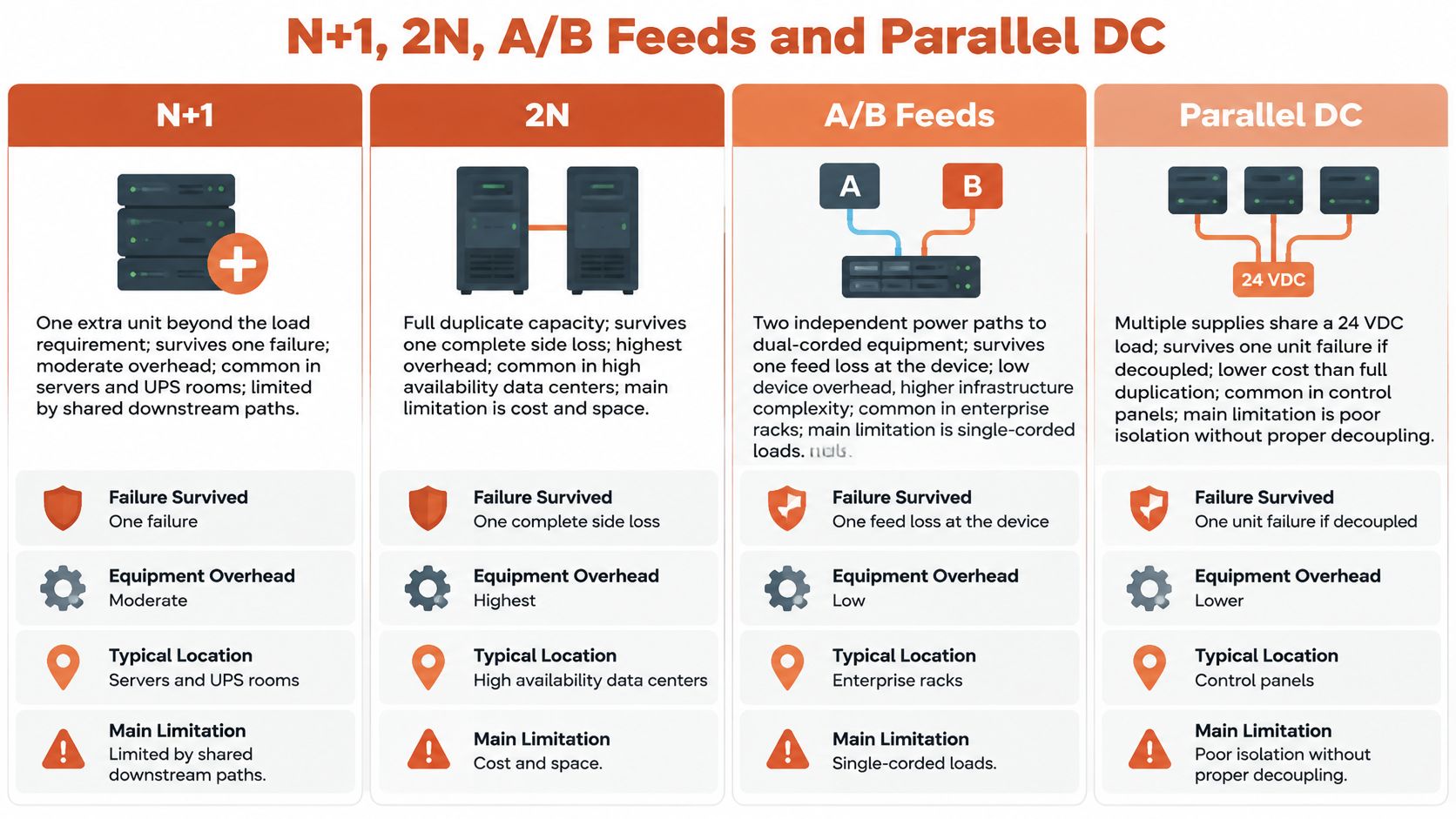
Distribution redundancy versus a parallel DC pair
A/B feeds describe separate power paths to the equipment. They don't, by themselves, establish how much reserve generation or UPS capacity exists upstream. Dual-corded equipment must operate correctly when either feed disappears; single-corded equipment needs a suitable transfer arrangement if it's to benefit from both paths.
Confirm the load's actual input behavior. A device that normally draws from both inputs may place substantially more demand on the surviving path after a failure.
A parallel 1+1 DC arrangement is narrower. It protects a common DC load against a supply failure when the outputs are properly isolated and the survivor has sufficient capacity. The common output wiring remains a separate design concern.
Choose the lowest-overhead arrangement that addresses the required event. Don't buy complete duplicate infrastructure to solve a replaceable module problem, and don't describe a spare module as protection against losing an entire distribution path.
Availability Tiers and What the Downtime Figures Mean
The Uptime Institute tier framework, summarized in an Electric Power Research Institute publication, associates Tier I through Tier IV with approximate availability levels of 99.67%, 99.74%, 99.98%, and 99.995%, respectively. The table translates those rounded percentages into approximate annual downtime; these are reference calculations, not a guarantee of site performance.
Uptime tiers, power paths and annual downtime
| Tier | Power path design | Approximate availability | Approximate annual downtime |
|---|---|---|---|
| Tier I | Single power path, no redundant components | 99.67% | About 28.9 hours |
| Tier II | Single distribution path with redundant components | 99.74% | About 22.8 hours |
| Tier III | Multiple power paths, redundant components, concurrent maintainability | 99.98% | About 1.75 hours |
| Tier IV | Multiple active paths, fault-tolerant architecture | 99.995% | About 26.3 minutes |
The distinction between Tier II and Tier III is particularly useful during design review. Adding redundant components to a single distribution path doesn't necessarily let maintenance personnel remove that path from service.
Maintainability is an operating requirement
Concurrent maintainability means the architecture allows required maintenance without shutting down the supported load. That demands suitable isolation points, available capacity, workable procedures, and access to the equipment being serviced.
For a facility that can schedule production shutdowns, a simpler architecture may be appropriate. For continuous operations, planned maintenance can be as important a design driver as unexpected failure. The engineering team needs to evaluate both.
A tier describes the facility architecture, not an individual supply's mean time between failures, or MTBF. Installing a highly rated component in a single distribution path doesn't change the path's maintainability or remove its common failure points.
Convert the target into purchasing requirements
An availability objective becomes useful when engineers translate it into requirements procurement can verify:
- Topology: Define whether reserve module capacity or independent supply systems are needed.
- Capacity margin: Establish the available capacity during failure and maintenance conditions.
- Transfer method: Confirm how the load receives the alternate source and whether it tolerates the transition.
- Maintenance procedure: Identify what can be isolated, who performs the work, and what remains energized.
Don't use an annual downtime figure as permission for one interruption of that duration. A process may tolerate scheduled maintenance but not an abrupt control-power loss, even if both occupy the same amount of time.
Set allowable downtime and interruption behavior first. Then select the architecture that supports those requirements, rather than assigning an availability label after the equipment has been purchased.
Decoupling and Sizing 24 VDC Redundant Supplies
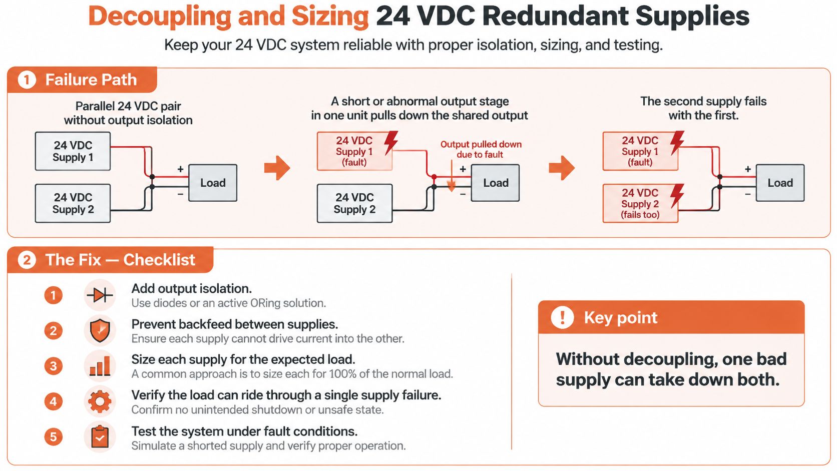
A parallel DC pair without output isolation can fail through its shared output connection. A short or abnormal output stage in one supply may pull down the common bus, leaving the healthy supply unable to maintain load voltage.
Rockwell Automation's redundancy application guidance calls for electrical decoupling, separate input protection, and individual supply monitoring. A redundancy module or suitable decoupling diodes prevents the healthy unit from feeding a fault through the failed supply's output.
Check isolation before adding capacity
Start at each output terminal and trace the connection to the load. Identify where reverse current is blocked, how the isolation device behaves under a fault, and whether the common output connection remains accessible for inspection.
A MOSFET redundancy module can provide the required output isolation, but its suitability still needs checking. Confirm input-channel ratings, total output rating, permitted voltage range, thermal limits, terminal capacity, and the manufacturer's required wiring arrangement.
The failure mechanism and corrective checks are illustrated below.
Give each supply its own input fuse or breaker. Coordinate protection so a fault in one branch doesn't unnecessarily disconnect the healthy branch; installing separate devices doesn't prove selectivity.
Use the industrial fuse selection guide to support review of fuse characteristics, then check the actual supply instructions and upstream protective-device information. Input inrush, interrupting capability, conductor protection, and the available fault current all need appropriate consideration.
Where practical, connect supplies to different phases or independent mains circuits. If phase-loss operation is required, verify that capability for the selected three-phase supply under the intended load and operating conditions rather than assuming it from the input designation.
Calculate the load after failure
Rockwell Automation's redundancy reference manual illustrates a load of up to 10 A supported by two 10 A supplies and a dual-input MOSFET redundancy module. The important arithmetic is what remains available after a supply fails, not the sum of the installed nameplate ratings.
The following worked examples use those supply ratings and assume equal current sharing, no derating, and an appropriately rated isolation arrangement. Percentages are calculated against each supply's nameplate current, not a guaranteed operating margin.
Load share in normal operation and after one failure
| Load | Topology | Units installed (10 A each) | Load per unit normally | Load per unit after one failure |
|---|---|---|---|---|
| 10 A | Single supply | 1 | 10 A (100%) | No power, no redundancy |
| 10 A | 1+1 | 2 | 5 A (50%) | 10 A (100%), no margin |
| 20 A | Intended 1+1, insufficient capacity | 2 | 10 A (100%) | Cannot carry the load, undersized |
| 20 A | N+1 | 3 | About 6.7 A (67%) | 10 A (100%), limited margin |
The intended 1+1 arrangement supporting the larger load can meet its steady-state demand under the stated assumptions, but it isn't redundant. Both supplies are required for normal operation. Calling it redundant on a drawing doesn't create surviving capacity.
A supply pair can have enough combined capacity to run the load and still have no capacity redundancy at all.
Equal sharing is also an assumption to verify, not an automatic result of parallel wiring. Output-voltage differences and the supply's sharing method affect how much current each unit delivers.
Apply derating and review the complete BOM
Use the manufacturer's curves for the actual enclosure temperature, input conditions, mounting orientation, and required clearances. A nameplate rating isn't a substitute for the permitted continuous output in the installed environment.
Check transient demand as well as steady-state current. Contactors, field devices, and capacitive loads can impose demands that aren't apparent from a simple list of nominal operating currents. Confirm the supply's overload behavior and the load's voltage tolerance together.
The component-level BOM review should cover:
- Output isolation: Specify the redundancy module or decoupling devices and their channel and output ratings.
- Input protection: Include an individual protective device for each supply, with coordination reviewed.
- Voltage settings: Equalize outputs as instructed and enable parallel-use mode where supported.
- Monitoring: Specify separate DC-OK contacts or equivalent signals and the required control-system inputs.
- Approved substitutions: Match isolation behavior, operating ratings, terminals, monitoring, and manufacturer compatibility, not just nominal voltage.
- Installation documentation: Include wiring instructions, applicable compliance documentation, and the final approved arrangement.
Order the supplies and redundancy module as a coordinated assembly of compatible components. A substitute that fits the DIN rail may still change current sharing, alarm behavior, thermal requirements, or protection.
Final selection and sizing must follow manufacturer instructions, applicable NEC and UL requirements, and the project engineer's review. Redundancy doesn't waive ordinary requirements for safe installation, conductor sizing, protection, or service access.
Testing and Monitoring a Redundant Supply System
A redundant arrangement remains unproven until personnel verify its behavior under the intended operating conditions. A healthy common output voltage alone doesn't establish that every supply is available.
Wire each supply's DC-OK signal to a separate PLC or control-system input. A failed unit should generate an actionable maintenance alarm while the remaining capacity still supports the process. Treat loss of all required control power as a shutdown condition, with responses determined by the process safety and controls design.
Establish a commissioning baseline
Use a DC-capable clamp meter on each individual output conductor to measure load current. Record operating conditions, current distribution, and output voltage against the manufacturer's permitted limits.
Check the alarm at the operator interface, not just at the supply terminal. The maintenance team needs a clear equipment identifier and response instruction.
Test the intended failure safely
A planned test should include these steps:
- Authorize the work: Confirm the maintenance window, supported load, isolation method, and recovery procedure.
- Verify indication: Isolate a supply using the approved method and confirm its individual alarm reaches the control system.
- Check the survivor: Measure current and output voltage while the remaining supply supports the required demand.
- Restore and document: Return the isolated unit to service, verify sharing and alarm clearance, and log the results.
Don't simulate an output short unless the manufacturer and an engineered test procedure explicitly permit it. Don't assume a removable module is hot-swappable.
All testing must follow manufacturer instructions and site lockout procedures and be performed by qualified personnel. Energized measurements require the site's applicable electrical safe-work practices.
This test exercises the supply layer only. Upstream distribution, transfer equipment, and communications paths require separate acceptance checks, with their own failure conditions and recovery criteria.
Failures That Duplicate Hardware Cannot Prevent
A shared upstream breaker can disconnect both supplies without either supply failing. The same boundary problem applies to the shared batteries, transfer equipment, and feeds identified at the start: duplicated components don't protect against every dependency outside their terminals.
Controllers, firmware, and maintenance practices add less visible common-cause paths. A common controller may issue the same incorrect command to both sides, while identical firmware can expose both units to the same triggering condition.
Review control and maintenance independence
Mounting supplies in the same enclosure also exposes them to common environmental conditions. Excessive temperature, contamination, or damage to a shared wiring route can affect both units together.
The maintenance procedure deserves the same scrutiny as the schematic. Ambiguous disconnect labels, shared alarm bypasses, or a work instruction that isolates both paths can defeat an otherwise sound design.
- Control dependency: Identify common controllers, settings, communications, and firmware assumptions.
- Work boundary: Mark which devices and terminals remain energized during replacement.
- Disturbance exposure: Review grounding and surge protection separately from capacity redundancy; the surge protection rating guide supports that selection discussion.
Keep network resilience separate
IEC 62439-3 defines Parallel Redundancy Protocol (PRP) and High-availability Seamless Redundancy (HSR) for industrial Ethernet, specifying switchover with zero recovery time when a network element fails.
PRP transmits duplicated information over separate networks. HSR uses two-port nodes in a ring or multi-port nodes in a meshed network. These mechanisms differ from a conventional standby link that must detect a fault and reconverge.
Their scope matters. A redundant DC supply can't compensate for a failed network switch or cable, and PRP or HSR can't correct a common upstream power fault. A substation controller may need independent provisions for both.
Review boundary: Ask what keeps the process working, not merely what keeps the power-supply output energized.
Trace each failure path from the utility connection through distribution, control power, controller, communications, and the return path. Assign a protective or redundant element to each required failure case, then mark any dependency without an independent backup. That marked drawing is more useful than a general statement that the panel is redundant.
Choosing the Right Topology for Your Load
Select redundant power supplies around the equipment's operating consequences, not around a preferred cabinet layout. The right arrangement for a replaceable control-power unit isn't automatically the right arrangement for a critical facility distribution system.
Use the topology diagram to compare where capacity and distribution-path separation belong.
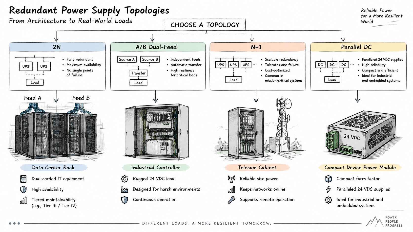
Match the arrangement to the application
For data centers with dual-corded IT, consider independent A/B distribution and complete duplicate supply capacity where the availability and maintenance requirements justify them. Confirm the equipment can operate on either input and that maintenance personnel can isolate the intended side safely.
For industrial control panels, an isolated parallel DC arrangement is often the appropriate starting point. The deciding issue is whether uninterrupted control power is required during a supply failure, rather than whether the panel has room for another DIN-rail device.
For process plants using modular UPS systems, N+1 can provide reserve capacity without duplicating the complete installation. Apply the same logic carefully to drive systems: an additional drive doesn't automatically provide a transferable operating path for a motor or process train.
For substations and real-time controls, specify the power and network requirements separately. If the communications architecture requires PRP or HSR, include compatible network equipment and an acceptance procedure alongside the control-power design.
The video below provides an additional visual reference for the power-system discussion.
Release a procurement-ready requirement
Before placing an order, record the application-level decisions:
- Required survival event: Identify whether the requirement covers a module, feed, supply system, or combined maintenance condition.
- Allowable interruption: State whether the load permits a transfer interruption and whether planned shutdowns are available.
- Essential load boundary: Identify which process functions must remain available and whether load shedding is permitted.
- Network obligations: Document substation or real-time communications requirements separately from power continuity.
- Approval authority: Name who accepts substitutions and signs off the final architecture.
Use the component-level decoupling and sizing checklist to complete the equipment schedule. Keep calculations, drawings, approved alternates, and operating procedures consistent through procurement and commissioning.
The purchasing decision is ready when the team can describe the failed condition, show the remaining capacity, and demonstrate how technicians restore redundancy safely. Extra equipment without those answers is an expense, not a verified continuity strategy.
ATEK Distribution can support BOM review, source hard-to-find redundancy modules and protective devices, and coordinate manufacturer review of proposed alternatives against the required isolation, ratings, monitoring, and compliance documentation. Send your load list, allowable downtime, and bill of materials to ATEK Distribution for project-specific sourcing support and a quote for your redundant power supplies.