
A 5/8-inch-diameter by 8-foot copper-clad steel rod is a common listed ground rod size; 8 feet of soil contact is the code minimum, while diameter must satisfy the listing and project specification. A larger diameter doesn't compensate for insufficient soil contact, and extra length doesn't make an otherwise unsuitable rod acceptable.
For engineers and buyers, ground rod sizes are a system-selection question, not just a catalog lookup. The right purchase includes the electrode, its material and listing, compatible connections, the grounding electrode conductor, and an installation plan suited to the soil.
Table of Contents
- Ground Rod Sizes and What Each Dimension Controls
- Material and Coating Options Compared
- Installing Ground Rods to Depth in Real Soil
- Sizing the Grounding Electrode Conductor
- Matching Rod Size to Each Application
- Measuring Ground Resistance and Soil Conditions
- Sizing Mistakes That Cause Rework
- Confirm the Rod Specification Before You Order
Ground Rod Sizes and What Each Dimension Controls
Rod length and diameter control different parts of the installation. The NFPA 70 development document identifies 2.44 meters (8 feet) of contact with earth as the installation requirement for rod and pipe electrodes. A rod's nominal length does not by itself confirm that the installed electrode achieves the required soil contact.
The 2023 NEC summary from EEPower states that rod or pipe electrodes must be at least 2.44 meters (8 feet) long. Check both the product length and the installed contact with earth.
Common sizes and the checks behind them
The table shows familiar purchasing descriptions, not blanket approvals. Confirm the specified material, listing, and project requirements for the application.
Common ground rod sizes, materials and typical use
| Size (diameter x length) | Typical material | Typical application | Listing or specification note |
|---|---|---|---|
| 5/8 in x 8 ft | Copper-clad steel | Common listed electrode for residential and light commercial grounding | Confirm listing and required soil contact |
| 5/8 in x 10 ft | Copper-clad steel | Longer soil contact where the design calls for more depth | Confirm listing and availability |
| 3/4 in x 8 ft | Copper-clad steel | Heavier-duty engineered systems | Project specification required |
| 3/4 in x 10 ft | Copper-clad steel | Engineered and federal specifications | Confirm listing and the applicable federal or project specification |
| 5/8 in x 8 ft | Galvanized steel | Sites where the design calls for zinc-coated electrodes | Confirm listing, coating requirements and soil compatibility |
| 5/8 in x 8 ft | Stainless steel | Corrosive soils or projects specifying stainless material | Confirm listing, grade and availability |
| 1/2 in x 8 ft | Manufacturer-specified metal | Limited applications only | Below the standard diameter threshold unless listed |
For stainless-steel, copper, or zinc-coated steel rod electrodes, Galvan Electrical's catalog description of NEC requirements states a 15.87 mm (5/8-inch) minimum, unless the rod is listed. A smaller listed electrode and an unidentified metal stake are not equivalent products.
Length and diameter solve different problems
Length controls soil contact and access to deeper soil layers. Diameter affects mechanical strength, resistance to driving damage, and the amount of metal available to withstand corrosion. Neither dimension guarantees a particular ground resistance.
Driving conditions matter. Rocky or compacted ground can make a rod harder to install; bending, a damaged head, or lost cladding can compromise the product. Select the driving equipment and accessories to suit the rod before ordering.
Purchasing rule: Specify diameter, length, base material, coating or cladding, and listing. A size-only description is incomplete.
If a supplier offers a longer rod than the approved item, assess handling clearance, driving equipment, connection details, listing, and the engineer's specification before accepting the substitution. Extra length alone does not establish compliance.
Material and Coating Options Compared
Choose the material for the soil and installation method, not for a general claim that one metal is always better. Copper-clad steel combines a conductive outer layer with a steel core that supports driving. Its suitability still rests on the actual product construction and the site's corrosion exposure.
Galvanized steel uses a zinc coating rather than copper cladding. Coating thickness, soil chemistry, and compatibility with connected metals deserve review before substitution. Neither a copper-colored surface nor a silver finish establishes the electrode's material or listing.
Ground rod materials compared on the criteria that affect selection
| Material | Corrosion behavior | Driving and strength | Listing and typical use |
|---|---|---|---|
| Copper-clad steel | Copper outer layer protects a steel core | Steel core supports driving; protect cladding from damage | Common listed option for general grounding |
| Galvanized steel | Zinc protection; service life is influenced by coating thickness and soil | Steel core supports driving | Confirm coating thickness and listing |
| Solid copper | High corrosion resistance in suitable environments | Softer metal; confirm suitability and driving method for rocky soil | Confirm listing and obtain a project-specific price |
| Stainless steel | High corrosion resistance in many soils; grade and chemistry matter | Strong; driving suitability requires grade and product review | Confirm listing and grade with manufacturer |
| Painted or enameled steel | Nonconductive coating makes it unsuitable as a made electrode | Mechanical strength doesn't resolve the coating problem | Excluded where OSHA prohibits nonconductive coatings |
Read the construction details
A supplier data sheet should identify the base metal, coating or cladding type, applicable listing reference, and intended burial conditions. Don't infer coating thickness from a product photograph or treat solid copper and copper-clad steel as alternate descriptions of the same item.
Ask the manufacturer to confirm:
- Corrosion suitability: Whether the proposed construction is appropriate for the site's known soil exposure.
- Driving accessories: Which heads, couplers, and tools are compatible with the electrode.
- Connection compatibility: Which clamps accept both the rod material and the specified conductor.
- Commercial terms: Current price, available quantity, and lead time for the exact catalog number.
Solid copper and stainless steel can be legitimate engineered choices, but they aren't universal upgrades. Compare the complete installed cost, including driving difficulty, accessories, documentation, and replacement risk. Treat unquoted prices and unconfirmed delivery dates as unknown, not as estimates suitable for a purchase order.
Installing Ground Rods to Depth in Real Soil
A correct catalog selection can still produce an unacceptable installation. Before driving begins, qualified personnel should confirm underground utility locations, available working space, the approved electrode layout, and the installation method.
Use this field sequence to coordinate the rod, soil location, and final inspection.
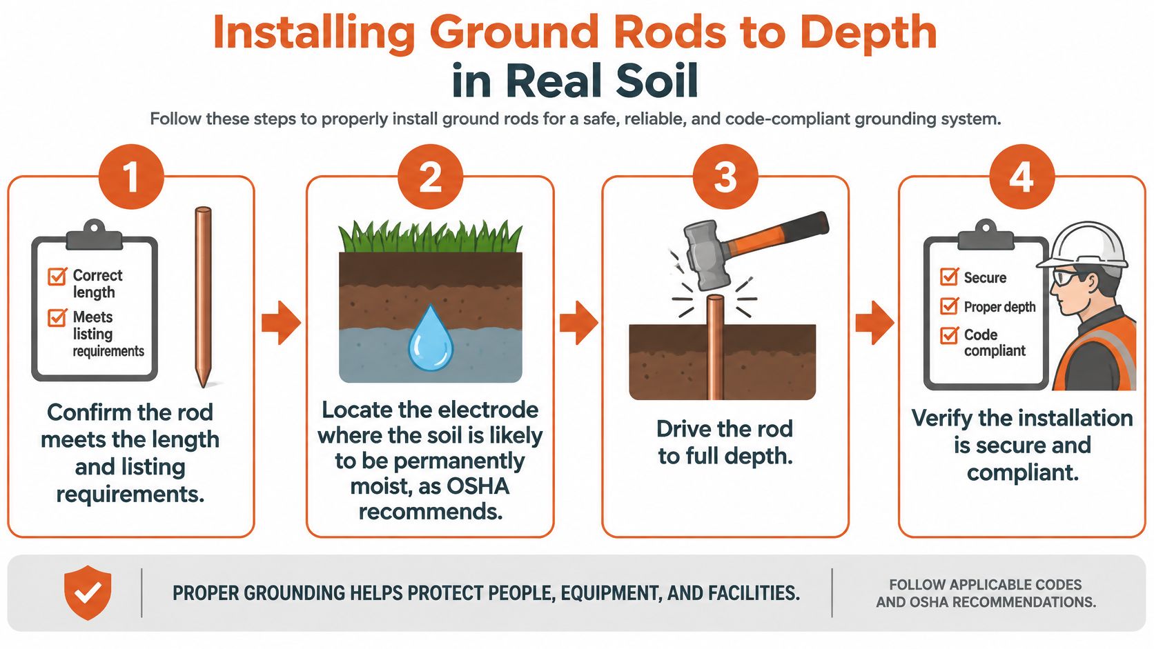
Installation sequence
-
Verify the electrode before driving. Compare its label and submittal with the approved material, dimensions, and listing. Discovering a mismatch after burial makes identification and correction harder.
-
Confirm the installation location. Choose the approved position with attention to persistent soil moisture, underground services, access, and conductor routing. Convenient placement beside the equipment isn't enough if the soil or layout is unsuitable.
-
Drive to the required installed depth. Use a compatible driving head and appropriate equipment. Don't cut off a refused rod or leave it partly exposed and assume its original length still proves compliance; rock refusal requires an approved installation response.
-
Make the conductor connection. Use a listed clamp compatible with the rod, conductor, and burial conditions, tightened to the manufacturer's instructions. A clamp that physically fits isn't necessarily suitable for the application.
-
Inspect and test as specified. Check mechanical security, conductor protection, and the required resistance test before acceptance. Record deviations while the installation remains accessible.
OSHA's construction grounding guidance requires made electrodes to be free of nonconductive coatings such as paint or enamel, recommends installation below the permanent moisture level where practicable, and requires a single rod, pipe, or plate electrode exceeding 25 ohms to be supplemented by another electrode at least 6 feet (1.83 meters) away. That supplemental-electrode rule isn't a guarantee that the completed system will meet a more demanding project target.
Resolve soil problems through design
Soil resistivity, moisture, corrosion exposure, and electrode geometry affect the result. A longer rod may reach more favorable soil, but increasing length or diameter won't reliably resolve every site condition. Sensitive industrial installations may require an engineered electrode arrangement rather than a larger version of the original purchase.
The following video provides additional installation context; use the applicable code, manufacturer instructions, and engineer's requirements for the actual work.
The grounding path must remain permanent and continuous. Give connections and routing the same inspection attention as the buried electrode.
Sizing the Grounding Electrode Conductor
The grounding electrode conductor isn't sized from the rod diameter. Increasing the electrode's diameter doesn't authorize a smaller conductor, and specifying a heavy conductor doesn't correct an unsuitable electrode.
EC&M's explanation of NEC Section 250.66 states that sizing generally follows the largest ungrounded service-entrance conductor, while the connection solely to rod, pipe, or plate electrodes need not be larger than 6 AWG copper or 4 AWG aluminum under the cited rules. This is a limit on the size required for that connection, not a prohibition against using a larger conductor or blanket permission to use either material in every location.
Separate the rod connection from the full system
A service can include connections to metal water pipe, a concrete-encased electrode, and other qualifying electrodes. The rod-specific sizing provision doesn't automatically govern those connections. Review each conductor segment by its function and termination points.
On the bill of materials, identify the rod connection separately from the other grounding electrode conductors and bonding jumpers. Include conductor material, connection method, physical protection, and terminal compatibility rather than leaving the installer to interpret a generic grounding-wire line item.
A conductor exception applies to a defined connection. It doesn't replace a review of the complete grounding electrode system.
Raceway bonding also deserves its own line of review. A split grounding bushing addresses a different connection detail from the electrode clamp; confirm the fitting's function and compatibility instead of treating grounding accessories as interchangeable.
Questions before conductor release
- Which electrodes are present? Identify the actual system, not only the rod shown in a purchasing schedule.
- What service conductors govern sizing? Obtain the approved service information rather than estimating from equipment appearance.
- Is this connection solely to rods? Confirm the conductor's complete route and what it connects along the way.
- Will the termination accept it? Check conductor material and size against the clamp or lug documentation.
- What local requirements apply? Resolve authority-having-jurisdiction interpretations before ordering.
This separation makes BOM review more useful. It prevents a correct rod connection from being mistaken for a correctly specified grounding electrode system.
Matching Rod Size to Each Application
An electrode suitable for a building service isn't automatically the right purchase for a generator, fence energizer, or sensitive equipment installation. Identify the governing document before selecting the catalog item. The application determines which questions need engineering review and which require manufacturer confirmation.
For a service entrance, review the grounding electrode system as a whole. For a portable generator, establish how the generator will supply loads and what the manufacturer requires before assuming that a separate rod is necessary.
Ground rod sizing questions by application
| Application | Typical electrode arrangement | Sizing question to confirm | Governing reference |
|---|---|---|---|
| Service entrance | Rod plus other electrodes present in the system | Which other electrodes are present, and what conductor sizing applies? | NEC and authority having jurisdiction |
| Portable generator | Rod or system as the generator manual directs | Does this operating configuration require an electrode, and what does the manual specify? | Generator manufacturer and applicable code |
| Electric fence | Rod count and spacing per energizer design | What rod size and count does the manufacturer specify for these soil conditions? | Energizer manufacturer instructions |
| Industrial or sensitive equipment | Multiple electrodes or engineered system where required | Can the proposed arrangement meet the specified resistance target? | Engineer specification and applicable code |
| Federal or public-sector project | Electrode defined by the contract specification | Are diameter, length, material, and required listing matched exactly? | Project specification |
Application details that change the order
Fence grounding is part of the energizer's operating arrangement. Obtain the manufacturer's electrode material, count, and layout requirements rather than importing a building-service detail into that application.
For industrial equipment, distinguish an equipment manufacturer's performance requirement from a generic electrode description. If the specification calls for a measured result, request the acceptance method and responsible testing party before releasing the order.
Public-sector procurement adds a documentation issue: a commercially available substitute can still conflict with the contract. Submit the proposed alternative with a side-by-side comparison of construction, listing, dimensions, and connection accessories. Availability alone isn't approval, even when the substitute appears mechanically more substantial.
Measuring Ground Resistance and Soil Conditions
A dimensionally acceptable electrode doesn't establish the resistance of the installed system. Soil resistivity describes how strongly the soil opposes current flow, while electrode resistance describes the installed electrode's electrical relationship with the surrounding earth. Buyers need the distinction because soil investigation and installation acceptance are different tasks.
A fall-of-potential test commonly uses auxiliary test electrodes placed away from the electrode under test. The test technician follows the instrument manufacturer's placement and measurement procedure, checks whether the test geometry is valid, and confirms the method with the engineer.
Choose a test method that fits the site
Space restrictions, buried conductive infrastructure, and parallel grounding paths can affect the measurement. A clamp-on tester isn't automatically a substitute for a fall-of-potential test, particularly where the required return paths aren't present. Specify an appropriate instrument and method rather than accepting any displayed resistance value.
For preconstruction investigation, a four-pin method such as the Wenner method estimates soil resistivity at different probe spacings. Engineers can use those measurements to evaluate whether deeper electrodes, a distributed arrangement, or another engineered solution is appropriate. Use applicable guidance such as IEEE 81 with the project's testing requirements.
Test-record check: Keep the method, instrument identification, electrode layout, soil conditions, and measured result together. An isolated resistance value is difficult to evaluate later.
Turn measurements into procurement decisions
Moisture and temperature can change readings. A measurement made after rain may not represent dry conditions, so record the environmental context and let the engineer determine whether further testing is needed.
Agree on the acceptance test before installation and complete it before energization where the commissioning plan requires. Retain the result with the electrode submittal and as-built layout.
Procurement should request the resistance target, test method, and corrective-work responsibility before fixing the electrode quantity. If testing identifies an unacceptable result, obtain an approved design response rather than purchasing additional rods without a layout.
Sizing Mistakes That Cause Rework
Most purchasing mistakes begin with a description that sounds complete but omits an acceptance criterion. A line item reading ground rod leaves the receiving team without enough information to distinguish a conforming product from a convenient substitute.
Use the following checks before shipment, while corrections can still be handled through documentation rather than excavation.
-
Treating extra length as equivalent construction. A longer but thinner rod can behave differently during driving and may not meet the approved listing or specification. Compare diameter, construction, and listing independently before approving the change.
-
Ordering conductor from rod size. This can leave other electrode connections incorrectly specified even when the rod connection is acceptable. Review the grounding diagram and identify each conductor's endpoints on the BOM.
-
Accepting an unidentified surface coating. Paint, enamel, metallic plating, and bonded cladding aren't interchangeable. Request the manufacturer's material description instead of accepting a sales photograph as evidence.
-
Buying an electrode before establishing the performance requirement. An apparently economical purchase can lead to redesign when the installation misses its acceptance target. Confirm the testing plan and engineered layout before locking in the quantity.
-
Using an incomplete distributor listing. Missing diameter, length, material, or standard leaves the order open to interpretation. Ask for the manufacturer catalog number, data sheet, and required compliance documentation.
-
Leaving the specification off the purchase order. Later substitutions become harder to assess when the order identifies only a commodity name. Reference the approved submittal and record any accepted alternative in writing.
Make receiving inspection practical
Give the receiving team a short acceptance package: approved catalog number, identifying dimensions, material description, required markings, and accessory list. They shouldn't have to interpret the electrical design to detect the wrong shipment.
Keep damaged products separate for disposition. A bent rod, damaged connection surface, or compromised cladding warrants review before use, not an assumption that burial will make the damage irrelevant.
The useful purchasing habit is simple: resolve ambiguity before the rod ships. Written approval is easier to manage than a field argument over whether an unreviewed substitute is close enough.
Confirm the Rod Specification Before You Order
The best ground rod specification connects the design requirement to a product that can be identified, installed, inspected, and documented. Release the order only when the responsible parties agree on those details.
Local adoption matters as much as the code edition named in a general reference. For Minnesota projects, the discussion of Minnesota NEC adoption changes is a starting point for identifying questions to verify with the permitting authority, not a substitute for that authority's requirements.
Purchase-order release checklist
- Governing requirements: Record the adopted code edition, local amendments, utility requirements, and applicable project specification.
- Dimensions: State diameter and length explicitly rather than relying on a catalog family name.
- Construction and listing: Identify base metal, coating or cladding, required listing, and manufacturer documentation.
- System connections: Confirm conductor sizes, clamp compatibility, burial suitability, and any required physical protection.
- Performance and layout: Record the resistance target, test method, installation locations, and approved electrode quantity.
- Substitution control: Name the approval authority and retain the accepted alternative with the reason for substitution.
Use this checklist when reviewing the order and the supplier's acknowledgment.
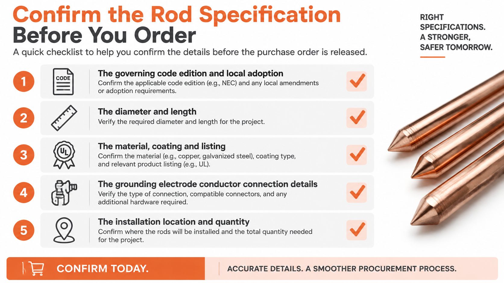
Keep alternatives tied to approval
When the specified item is delayed, compare the proposed replacement against each acceptance criterion. Confirm accessory compatibility and documentation availability at the same time, so an approved rod doesn't arrive without a usable connection method.
Ask the sourcing partner to coordinate unresolved construction or listing questions with the manufacturer. Engineering approval should remain with the designated project authority; distributor support should make that decision better documented, not bypass it.
Before comparing ground rod sizes or requesting a quote, answer the buyer's first question: Is the specification set by the code, the engineer, or the manufacturer's instructions?
ATEK Distribution can help review rod, clamp, and conductor consistency on your BOM, coordinate manufacturer documentation, and source alternatives for project approval when specified components are delayed. Visit ATEK Distribution with your grounding specification, required quantities, and delivery schedule to request project-specific sourcing and quotation support.