
The wall is finished, the raceway is installed, and the crew is ready to pull conductors. Then someone notices that the LB cover faces the studs. The turn fits the drawing, but nobody can reach the opening without disturbing the finished work or opening the raceway.
That's the distinction that matters when choosing conduit body types. The letter determines the route, but cover access, pulling space, and the intended wiring work determine whether that fitting will serve the installation.
Table of Contents
- Conduit Body Types at a Glance
- Hub Count Families and What They Route
- Field Examples for Each Letter
- Cover Access After the Wall Is Closed
- Pull Space and Raceway Fill Limits
- Splices Terminations and Marked Volume
- Listings Materials and Standards Crosswalk
- Call Out the Body on the Bill of Material
Conduit Body Types at a Glance
A conduit body is a separate portion of a conduit or tubing system that provides interior access through a removable cover at a raceway junction or terminal point. Contractors use it to pull and inspect conductors, change direction, and, where the product and installation permit, make splices without installing a full junction box.
The enclosure classification is important. OSHA's electrical definitions specifically exclude FS and FD boxes, along with larger cast-metal and sheet-metal boxes, from the conduit-body category. Those products aren't interchangeable pull points just because each has a removable cover.
Read the letter from the cover side
Use a consistent viewing position: stand with the cover facing you. LL leaves left, LR leaves right, and LB leaves through the back, opposite the cover. Keep that convention on sketches, takeoffs, and purchase descriptions so the installer and buyer aren't interpreting the same letter from opposite sides.
Conduit body types by path and cover
| Body | Hubs | Path relative to cover | Typical routing job |
|---|---|---|---|
| Type C | 2, inline | Straight through under the cover | Pull or inspection access with no change of direction |
| Type LB | 2 | 90 degrees out the back, opposite the cover | Turn into or out of a wall while the cover stays on the open face |
| Type LL | 2 | 90 degrees to the left with the cover facing you | Left-hand turn that keeps the cover reachable |
| Type LR | 2 | 90 degrees to the right with the cover facing you | Right-hand turn, the mirror of an LL |
| Type T | 3 | Through run plus one branch | Tee where a branch raceway leaves the main run |
| Type X | 4 | Four-way cross | Intersection of two runs in one body |
A letter answers the routing question, not the entire selection question. It doesn't identify the compatible raceway, connection method, usable wiring space, body material, or environmental suitability.
Hubs on a listed body may match or provide a permitted transition between trade sizes. Don't infer that capability from a catalog photograph or assume a reducer makes every combination acceptable. Confirm the actual product configuration before releasing the order.
Practical rule: Treat the letter as a routing specification, then confirm the cover's removal path before release.
Check the installed envelope
The body has to fit more than the empty space shown on a conduit plan. Account for cover screws, screwdriver access, adjacent equipment, wall finishes, and the working position needed to guide conductors through the opening.
A compact fitting can solve a clearance problem while creating a pulling problem. A larger body can improve conductor handling but interfere with equipment doors or adjacent services. Select the installed assembly, including its cover and connections, rather than the smallest outline that fits between drawn lines.
Hub Count Families and What They Route
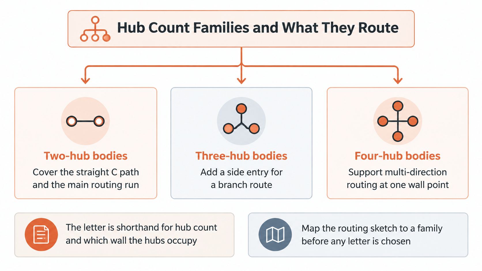
Map the raceway sketch to a hub-count family before selecting a catalog item. The letter is shorthand for hub count and which wall the hubs occupy.
The family layout makes that first decision easier.
Match the family to the raceway schedule
The IAEI guide to conduit bodies groups straight, LB, LL, and LR bodies as two-hub configurations, Type T as three-hub bodies, and Type X as four-hub bodies; it also notes that hubs may have the same or different sizes where permitted.
- Main routing run: Select the straight or turning family from the required continuation, not from whichever body is stocked.
- Branch connection: Check the branch against the raceway schedule, including its destination and connection style.
- Crossing runs: Reserve an X for a designed intersection using its hubs. Otherwise, a T or an appropriately selected box may produce a cleaner installation.
An unused hub isn't a spare knockout to leave open. If the design includes an unused opening, specify an identified closure suitable for the body and location.
Same-size hubs and listed reducing-hub configurations also need different purchasing descriptions. Confirm that the product permits the intended trade-size transition rather than assembling an undocumented substitute.
The letter belongs on the BOM because replacing LB with LL changes wall clearance, exit direction, and pulling geometry. A routing demonstration can help the buyer and installer compare the same orientation.
Field Examples for Each Letter
Use the cover-facing convention when walking these scenarios. Draw the cover as well as the conduit centerlines; a centerline-only sketch can hide the very obstruction that makes a fitting unusable.
Type C across a mechanical room
Say a straight 2-inch RMC run crosses a mechanical room between long sweeps and needs a covered pull point. A C body keeps the raceway in line while its cover faces the aisle, where the crew can guide conductors and inspect the interior.
Substituting an angle body doesn't provide equivalent access. It introduces an unnecessary turn and can force an offset that consumes the space intended for maintenance. Rotating the C cover toward the wall defeats the reason for installing it.
Type LB into a control panel
An EMT run follows a block wall and turns into the back of a control panel. An LB can keep the cover on the open wall face while the continuation leaves through the back toward the enclosure, provided the selected body and connections suit the EMT system.
An LL or LR substitution would send the continuation along the wall instead. Trying to recover the panel entry by rotating that fitting may put the cover against masonry. Compare the access requirement with the routing options discussed in this guide to a 90-degree conduit elbow, rather than treating every turning fitting as interchangeable.
Type LL along an equipment pad
Standing at the cover, the continuation needs to leave left along an equipment pad. An LL places that exit where the route needs it while keeping the access opening toward the service side.
An LR in the same location points toward the equipment instead. The crew may be able to add a field offset, but that workaround adds connections and changes the planned pulling route. Correct the body selection before fabricating the adjoining raceway.
Type LR beside a doorway
On the opposite side of a doorway, the continuation must leave right to clear the opening. An LR can place the hub away from the door swing while preserving access from the corridor or service aisle.
A left exit can land the hub or adjoining conduit in the door's travel. Check the actual door swing and trim, not just the rough opening. Moving the fitting after the conductors are installed is a much larger task than correcting the takeoff.
Type T feeding a local disconnect
A branch leaves a main rigid run for a local disconnect. Position the T so the crew can reach the branch pull and guide the conductors instead of dragging them blindly around an inside corner.
Rotating the body merely to simplify conduit alignment can move its cover out of reach. Also distinguish a raceway branch from an electrical tap: the routing arrangement doesn't establish permission to make a connection inside the body.
Type X at a designed intersection
Say crossing runs meet in an accessible ceiling service space and every hub is part of the design. An X can provide the intended intersection without piecing together an improvised collection of turning bodies.
It's a poor default for a branch that doesn't need the full cross configuration. A rotated or poorly located X can leave the cover above fixed equipment, and its additional openings don't resolve conductor-routing or circuit-separation requirements.
A fitting that saves conduit work but prevents the next conductor pull isn't a useful substitution.
Specify beyond the letter
The ABB conduit-body dimensional sheet shows that body length and internal volume change with trade size and configuration. The letter alone therefore isn't a purchasing description.
Send the dimension sheet with the proposed item, especially where equipment is already installed. Material, gasket construction, and listing compatibility require their own review rather than an assumption based on the shape.
Cover Access After the Wall Is Closed
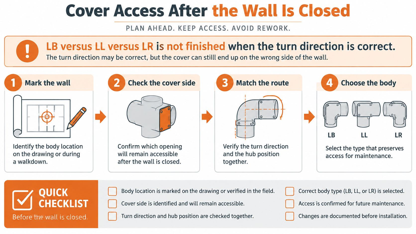
LB versus LL versus LR isn't finished when the turn direction is correct. The selection has to preserve service access after the building and equipment installation are complete, not just while the wall is open.
Use the drawing review and field walkdown to evaluate the same conditions. A markup that shows the cover face is more useful than a note saying “provide accessible fitting.”
This access-focused selection sequence keeps the final installation in view.
Walk the installed condition
- Mark the required turn. Trace the incoming run, continuation, and any branch on the raceway sketch. Identify the viewing direction before calling out the letter.
- Place the cover on the lasting open face. Include wall finishes, equipment cabinets, insulation, guards, and adjacent piping. Empty space during rough-in may not remain empty.
- Test removal access. Check that a hand and screwdriver can reach the fasteners and that the cover can lift away without moving other gear. Leave room to handle conductors, not merely loosen a screw.
- Match the exposure. Select the body, cover, and gasket assembly for wet, washdown, outdoor, or corrosive conditions. Adding a gasket to an unsuitable assembly isn't a substitute for the required identification.
- Verify raceway support. Show support near the body and at the intervals applicable to the wiring method. Don't leave the hubs carrying an unsupported run.
- Confirm metallic-system bonding. Verify continuity through the applicable listed hubs, locknuts, or bonding means. A painted joint isn't a bonding plan.
EC&M's guidance on metal-conduit requirements explains that raceways must permit conductor installation and removal without insulation damage and must be supported near conduit bodies and at prescribed intervals. Check the adopted code and the actual wiring method when determining those requirements.
Resolve the alcove before buying the fitting
Consider a panel alcove where an LR matches the drawn turn but leaves the cover facing a hypothetical 2-inch gap beside a transformer. The outline fits, yet a technician can't realistically remove the cover and guide a conductor through that space.
If the adjoining raceway can be rerouted, an LB with its cover toward the aisle may resolve the access problem. That change needs a coordinated sketch showing the revised entry and continuation, not a handwritten instruction to substitute letters.
Make this check before adjoining runs are cut and threaded. Otherwise, fixing the cover orientation may require replacing fabricated conduit, relocating supports, and revising the enclosure entry.
Walkdown check: Evaluate the fitting from the position where a technician will actually remove the cover.
Access review and pull-space review answer different questions. A reachable opening doesn't prove adequate internal geometry, and adequate internal geometry doesn't make a blocked cover serviceable.
Pull Space and Raceway Fill Limits
Separate ordinary bodies from reduced-dimension bodies before approving a compact fitting. Hub size alone doesn't establish whether the actual conductors can be pulled through it without damage.
The UL 514B document preview describes the six-times angle-pull spacing, eight-times straight-body length, internal-area provisions, and listed reduced-dimension conditions summarized below. Apply these checks within their applicable code and product scope, not as a complete sizing method for every arrangement.
Pull-space and fill limits for conduit bodies
| Check | Applies to | Minimum or limit | Exception |
|---|---|---|---|
| Entry to opposite wall | Angle and U pulls, including LB, LL, LR, and T | Six times the trade size of the largest raceway | Does not apply when the opposite wall is the removable cover |
| Body length | Body that does not change wiring direction | Eight times the trade size of the largest connected tubing or conduit | Listed area rules still apply |
| Internal cross section | Listed conduit bodies | Minimum area based on the largest connected raceway under UL 514B | Use the listed product, not a field guess |
| Reduced-dimension body | Compact bodies below ordinary spacing | Manufacturer must mark maximum conductor size and quantity | Design must pass a wire-pull test with no insulation damage |
| Conductor fill | Conductors in the connected raceway | Stay within fill allowed for that complete conduit or tubing system | A larger body is not an unrestricted expansion chamber |
Understand what the opposite wall means
The cover exception is significant because it changes which internal measurement controls. Don't measure blindly across a catalog outline without locating the entry and the actual opposite surface.
For a hypothetical application of the rule, a 2-inch angle entry requires 12 inches to the opposite wall when that wall isn't the removable cover, using the spacing relationship in the cited document. That illustration isn't permission to ignore other applicable arrangement, conductor, or listing requirements.
A compact body may be acceptable under its listing even though it doesn't meet ordinary spacing. The manufacturer's conductor markings and applicable instructions establish that route to acceptance; an installer's ability to force a bundle through the opening does not.
Review the actual conductor combination
Approve a reduced-dimension body against the conductor schedule, not an informal statement that it “takes large wire.”
- Identify the conductors. Record quantity, size, insulation type, and the intended pull path through the body.
- Read the marking. Compare the actual combination with the manufacturer's permitted conductor size and quantity.
- Check pulling instructions. Use the specified pulling lubricant when required and verify compatibility with the conductor insulation.
- Inspect the opening. Confirm that the installed cover can be removed and that conductors can be guided without scraping edges.
OSHA's wiring-method requirements keep allowable cable fill within the limits for the complete conduit or tubing system. Extra space inside the body isn't an unrestricted expansion chamber for an overfilled raceway.
For larger feeder work, a 4-inch conduit selection review should therefore include the connecting fittings and conductor schedule, not just the straight raceway. Splices, terminations, and devices introduce a separate enclosure-volume question that a successful pull-space check doesn't answer.
Splices Terminations and Marked Volume
A conduit body isn't necessarily limited to pulling access, but permission to splice is conditional. Electrical Contractor's NEC commentary-change-part-9) explains that a body containing splices or terminations needs its cubic-inch volume marking and an applicable fill calculation.
An unmarked body isn't an ordinary junction box just because its cover comes off. Verify a durable manufacturer volume marking, the product's permitted use, and sufficient calculated volume before adding a splice, termination, or device.
Check a proposed retrofit
Say a crew wants to land a tap and terminal block inside an existing LB to avoid installing another enclosure. That proposal needs a documented review, not a visual judgment that the components appear to fit.
- Read the marking. Record the usable marked capacity and identify the body and cover assembly.
- Calculate the contents. Account for conductors, splices, and devices using the applicable enclosure-volume rules. Include equipment-grounding and bonding conductors when those rules require them.
- Verify the intended use. Confirm that the listing and instructions permit the proposed termination arrangement.
- Reject an unsuitable body. If the capacity is unmarked, insufficient, or inconsistent with the intended use, select an appropriate enclosure.
Keep raceway conductor fill separate from the body's enclosure-volume calculation. Neither calculation replaces the other.
Large-conductor retrofits and control modifications deserve particular scrutiny because terminal hardware can consume working space quickly. Verify the access wording and volume provisions against the NEC edition enforced by the authority having jurisdiction, then confirm the manufacturer's listing and markings before approval.
Listings Materials and Standards Crosswalk
Use standards to answer specific selection questions. This crosswalk isn't a substitute for the adopted code, the product listing, manufacturer instructions, or project engineering requirements.
The ANSI/NEMA FB 1 standards listing identifies performance expectations for fittings, cast-metal boxes, and conduit bodies used with the covered raceway and cable systems under NFPA 70. Keep that performance scope distinct from the product-listing and installation questions.
Match the document to the review
Standards that govern conduit body selection
| Document | Question it answers | Verify on the submittal |
|---|---|---|
| NEC (NFPA 70) | Access, support, undamaged conductor installation and removal, and volume when splices are present | Adopted edition and whether the body will contain splices or only a pull |
| UL 514B | Listing of bodies for EMT, IMC, RMC, liquidtight flexible conduit, and rigid PVC | Listing mark, raceway compatibility, and hub or thread type |
| ANSI/NEMA FB 1 | Performance expectations for fittings, cast-metal boxes, and conduit bodies on those raceways | That the specified fitting is in scope for the raceway system |
| OSHA definition | Conduit body class, and exclusion of FS and FD boxes and larger cast or sheet-metal boxes | That the item is specified as a conduit body and not as a box |
For the NEC review, identify the edition the authority having jurisdiction enforces. Don't place a generic compliance statement on the submittal without documenting the intended installation.
For the listing review, match the exact catalog item to the connected raceway. A manufacturer may offer similar-looking bodies with different connection systems, and a family name doesn't prove that every member suits every raceway.
Match materials and connections
Threaded malleable-iron or aluminum bodies are common choices for rigid metal conduit and intermediate metal conduit when the product is identified for that system. EMT bodies need the setscrew or compression connections they're listed to use; don't assume a threaded opening directly accepts EMT.
PVC bodies belong with compatible PVC conduit and the specified joining method. For metallic systems exposed to chemicals or persistent moisture, evaluate corrosion resistance across the complete assembly, including covers, fasteners, and connecting fittings.
- Wet or outdoor exposure: Verify the assembled body, cover, gasket, and entries for the location.
- Washdown service: Check suitability for the actual cleaning exposure rather than relying on a gasket's presence.
- Corrosive service: Compare the materials with the process environment; a stainless-steel conduit system still needs compatible fittings and project-specific review.
- Hazardous locations: Require equipment identified for the applicable location. An ordinary covered body doesn't establish that suitability.
Record the listing, raceway material, hub or thread type, cover and gasket construction, corrosion resistance, and location suitability in the procurement package. Include the dimension sheet as well: trade size doesn't establish the installed length or usable internal volume.
Call Out the Body on the Bill of Material
A useful conduit-body callout lets purchasing order the intended assembly without interpreting a field sketch. Keep it on the same line item as the raceway schedule reference so the buyer, reviewer, and installer work from a common specification.
Don't release an order described only as “LB to suit.” That leaves the supplier guessing about connections, material, cover, and whether the body will contain anything beyond through conductors.
Build a complete buying description
- Body type: Identify C, LB, LL, LR, T, or X and reference the marked-up routing detail.
- Hub configuration: State each hub's trade size and its threaded, setscrew, compression, or other specified connection style.
- Raceway system: Identify the connected raceway so the proposed body and fittings can be checked together.
- Body material: Name the required material and any project-specified finish or corrosion-resistance requirement.
- Cover assembly: Include the cover, gasket, and required fastening arrangement. Clarify whether these arrive with the body or as separate items.
- Intended wiring work: State whether the body is pull-only or will contain splices, terminations, or devices. Require the applicable volume marking and supporting calculation where needed.
- Location identification: Document wet-location, corrosive-service, or hazardous-location requirements that apply.
- Submittal documents: Request the listing information, dimensional drawing, conductor limitations, and installation instructions for the exact item offered.
A supplier can then flag a missing field before it becomes a field substitution. That is especially valuable when the specified configuration is difficult to obtain and the purchasing team is comparing available alternatives.
Review an alternate as an assembly
During a shortage, a matching letter isn't enough to establish an approved equal. Another manufacturer's body may change the installed length, hub style, cover projection, conductor allowance, or marked volume.
Compare those fields against the actual installation and record the reviewer's disposition. Preserve the routing letter unless the responsible designer approves a coordinated routing change; an alternate letter can send the raceway in the wrong direction even when the nominal size matches.
Release check: Approve the exact catalog item and assembly, not a promise that the replacement is “the same type.”
Before shipment, confirm that the cover faces the accessible side, support is addressed, and the pull fits either the applicable ordinary dimensions or the compact body's actual conductor marking. Don't accept proposed splices without the required marked volume and calculation.
Selecting conduit body types is ultimately a coordination task between routing, maintenance, and procurement. Send the raceway schedule and a sketch with the cover face marked when asking for availability or alternate review, rather than asking the buyer to guess a substitute letter.
ATEK Distribution offers conduit-body and related-fitting sourcing, BOM review, hard-to-source alternatives, manufacturer coordination, and listing or compliance documentation for industrial, facility, and government projects. Visit ATEK Distribution with your raceway schedule and marked-up routing sketch to request an availability check and support evaluating proposed alternatives.