
A contractor has just replaced a distribution panel, selected an SPD with an impressive maximum surge-current rating, and submitted the cut sheet for approval. The control panel downstream still experiences unexplained failures. That outcome is frustrating, but it isn't unusual. The largest kA number on the enclosure doesn't tell you the voltage the connected equipment will see.
A reliable surge protection rating review starts with the complete electrical relationship: system voltage, Maximum Continuous Operating Voltage (MCOV), Voltage Protection Rating (VPR), SPD Type, protection modes, short-circuit current rating (SCCR), and installation geometry. The right device isn't necessarily the one with the biggest headline rating. It's the one that diverts the expected transient, clamps voltage within the equipment's withstand capability, and remains stable under normal system conditions.
Table of Contents
- Understanding Surge Protection Device Ratings
- MCOV and System Voltage Matching
- Voltage Protection Rating vs Surge Current
- UL 1449 SPD Types and Applications
- The Myths Behind Higher kA Ratings
- Selecting the Right SPD for Your Project
Understanding Surge Protection Device Ratings
A submittal lands on the desk with a bold kA figure at the top, yet the connected controls are still the part most likely to fail. That happens because an SPD rating block is a set of related limits and test values, not a single verdict on protection. NIST separates nominal system voltage, surge-current capability, and clamping voltage in SPD evaluation, which is the right starting point for any serious review (NIST guidance on protecting computers).
In industrial work, that distinction matters fast. Power supplies, PLC inputs, drives, networked devices, and instrument loops do not all tolerate the same let-through voltage, and the SPD with the highest surge-current headline is not automatically the better fit. I have seen acceptable current ratings paired with the wrong clamping behavior, the wrong modes, or poor lead layout. On paper the device looked strong. At the terminals, the equipment still saw too much voltage.
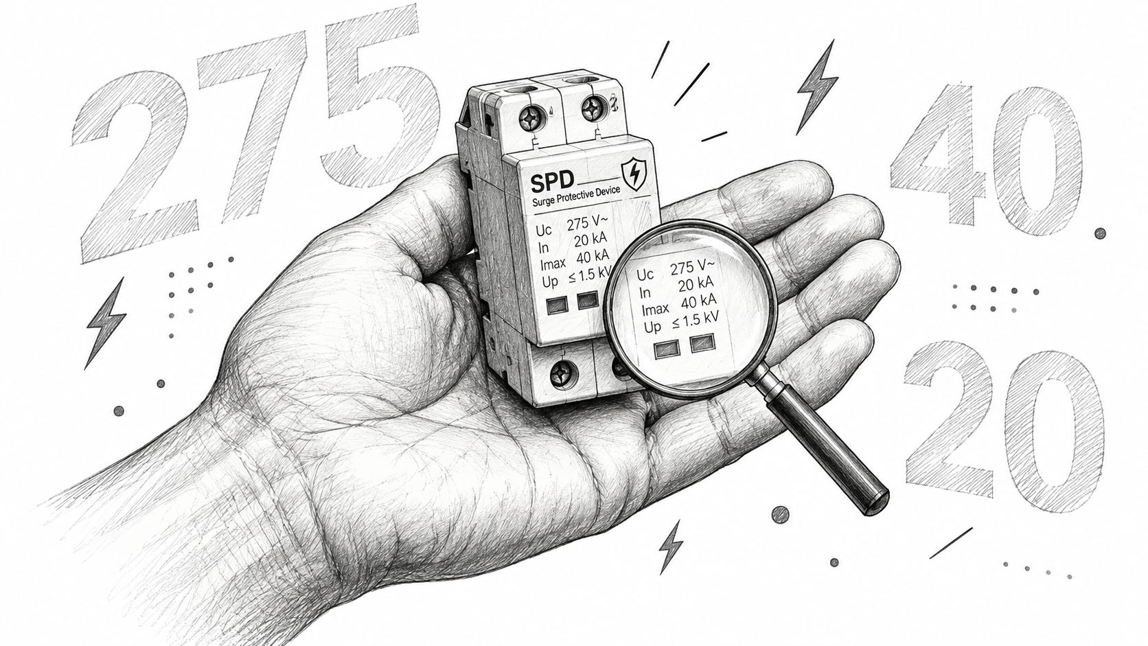
Read the complete rating block
Start with the electrical system and the load you are trying to keep alive. Confirm nominal voltage, phase arrangement, grounding scheme, and which conductors the SPD protects. Then read the rating block as a coordinated set of checks:
- MCOV: Verify it against the system configuration and normal steady-state voltage.
- VPR: Use it to judge the let-through voltage the equipment may be exposed to.
- In and Imax: Use these as current-handling indicators, not as a stand-alone selection method.
- SPD Type: Confirm the intended installation point under UL 1449.
- SCCR: Match it to the available fault conditions at the installation.
- Protection modes: Confirm the device covers the line-to-neutral, line-to-ground, neutral-to-ground, or line-to-line paths that matter in that panel.
Many reviews go off track at this point. The large kA number gets attention because it is easy to compare across cut sheets. The harder question is usually the deciding one, what voltage will pass downstream during the standardized event, and is that level acceptable for the connected equipment?
Practical rule: Use kA to screen candidates. Use VPR, MCOV, Type, SCCR, protection modes, and lead routing to decide whether the device actually fits the application.
For contractors, engineers, and facility teams, a usable submittal should let you verify those relationships without guesswork. A cut sheet dominated by one surge-current figure leaves the engineering decision incomplete. Reviewing ATEK's power and protection equipment in that context helps keep selection tied to the panel, the load, and the withstand limits of the equipment.
MCOV and System Voltage Matching
A surge protective device can look acceptable on a submittal and still be wrong for the system. I see this most often when the nominal voltage matches the panel label, but the MCOV does not match the actual voltage that appears across the protected modes. Under UL guidance, the SPD's normal operating-voltage rating and MCOV cannot be lower than the circuit's full line-to-line voltage, so selection has to follow the system configuration, not just the most familiar phase-to-neutral value (UL guidance on SPD ratings).
That distinction matters on a 480Y/277 V system. The phase-to-neutral voltage is 277 V, but the system also presents 480 V line-to-line, and the SPD has to survive the voltages seen in the modes it is designed to protect. Choosing the device from the 277 V number alone is how electrically incompatible SPDs end up in otherwise well-documented projects.
Why a low MCOV causes trouble
If MCOV is too low, the SPD can start to conduct during normal system variation instead of waiting for a transient. In a MOV-based design, that means heat, accelerated aging, and a higher chance of nuisance failure or internal disconnection long before the unit has done meaningful surge duty.
Going too far the other way also has a cost. A higher MCOV gives more steady-state voltage headroom, but it usually pushes the protection element to operate at a higher voltage as well. That reduces margin between normal operating conditions and the let-through voltage your equipment must tolerate. Manufacturers commonly advise selecting enough MCOV margin for the actual service conditions, then checking that margin against the specific product data, grounding method, voltage tolerance, and expected temporary overvoltage exposure.
The key point is practical. Apply the margin to the voltage in the protection mode you are using, not just to the nameplate system voltage.
| System Voltage | Required MCOV Minimum | Protection Mode Focus | Critical Consideration |
|---|---|---|---|
| 120/208 V | No lower than the circuit's full line-to-line voltage | Verify line-to-neutral, line-to-ground, and line-to-line modes as applicable | Confirm the wiring topology and each protected mode before selecting phase-to-neutral protection. |
| 120/240 V | No lower than the circuit's full line-to-line voltage | Review split-phase line-to-neutral and line-to-line protection | Check neutral treatment and line-to-line exposure, not just the 120 V circuits. |
| 480Y/277 V | No lower than the 480 V line-to-line condition | Confirm line-to-ground MCOV for 277 V paths and line-to-line suitability for 480 V paths | Don't select solely from the 277 V phase-to-neutral value. Evaluate line-to-ground exposure as well. |
Verify more than the nominal label
Nominal system voltage is only the first screen. Grounding arrangement changes what voltage the SPD elements see, especially on systems that are solidly grounded, impedance grounded, ungrounded, or otherwise configured outside the simplest wye case. Temporary overvoltage behavior matters too.
For procurement, the submittal should show nominal system voltage, wiring topology, MCOV by protection mode, and SCCR on the same document. If a quote lists only a product family and a maximum kA number, the voltage-matching work is still unfinished, and that is where avoidable application errors start.
Voltage Protection Rating vs Surge Current
Surge-current ratings and VPR answer different questions. The current rating describes the SPD's ability to divert transient current. VPR describes the standardized limiting voltage associated with what the protected circuit may experience during the test. For downstream electronics, that voltage relationship is often the more useful first comparison.
Under ANSI/UL 1449, VPR is determined with a 6 kV, 3 kA combination-wave generator using an 8/20 microsecond current waveform. The measured limiting voltage is averaged and rounded up to an assigned value such as 330, 400, 500, 600, or 700 V (NEMA surge protection FAQs).
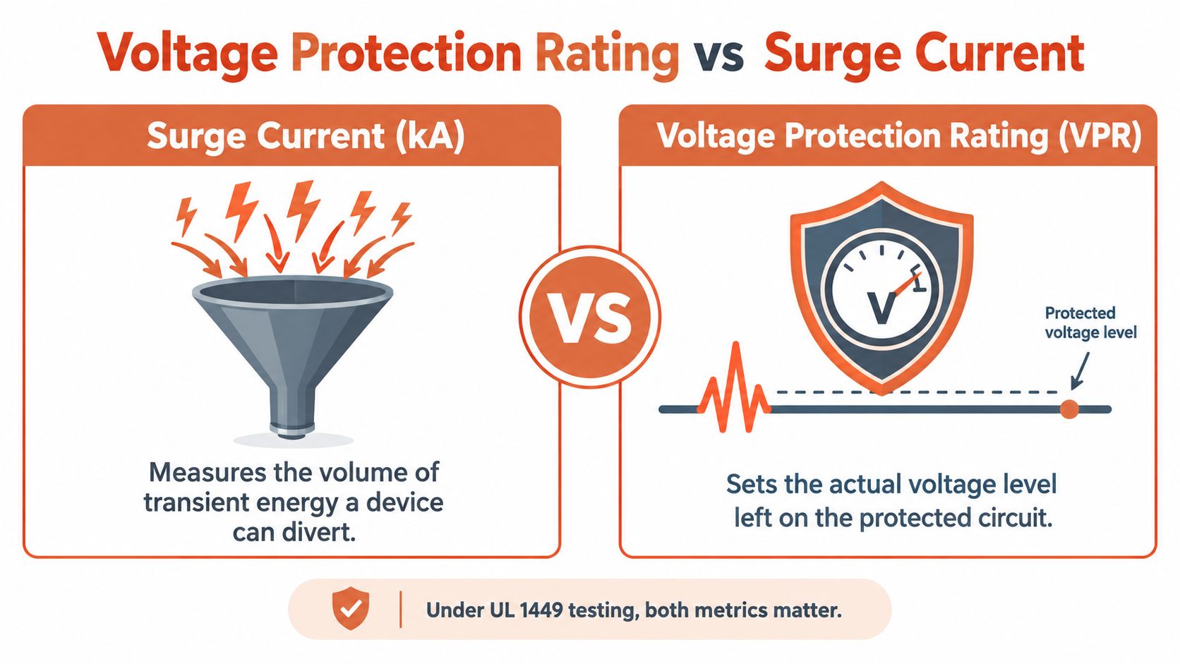
What VPR tells the engineer
A lower VPR generally indicates lower let-through voltage during the standardized test. That can be valuable when the protected equipment includes PLC inputs, industrial communication modules, measurement electronics, variable-speed drive controls, or other components with limited impulse withstand capability.
The comparison only works when the test context is comparable. Review VPR at the same system voltage, protection mode, installation topology, and test basis. A line-to-neutral VPR isn't interchangeable with a line-to-line value, and a favorable catalog number doesn't automatically represent the voltage at a remote load.
Published specification limits illustrate this voltage dependence. Common maximum VPR values include 700 V line-to-neutral and 1,200 V line-to-line for 120/208 or 120/240 V systems, while 480Y/277 V systems may permit up to 1,200 V line-to-neutral and 2,000 V line-to-line (Mersen surge protection information). Those values aren't a universal selection target. They show why the nominal system voltage must stay in the comparison.
The useful question isn't “Which SPD has the biggest kA rating?” It's “Which protection mode produces a compatible residual voltage at this equipment?”
Lead length changes the field result
The laboratory VPR belongs to a defined test setup. The installed result also depends on the conductors between the SPD and the equipment or bus. Connection inductance adds voltage during a fast current rise, so long, looped, or poorly bonded conductors can increase the transient voltage at the load.
That means a theoretically low-VPR SPD can underperform if the installer routes its leads through unnecessary bends or leaves excessive conductor length. Keep the connection short and direct, follow the manufacturer's routing instructions, and coordinate the bonding path with the panel construction.
Use the same discipline when evaluating related protection equipment. A technical guide to industrial fuse selection can help separate current interruption requirements from other protection decisions, but fuse ratings and SPD ratings aren't interchangeable. Each component must be matched to the fault, transient, voltage, and installation conditions it is designed to address.
Compare VPR with equipment capability
The equipment documentation should identify its impulse withstand or applicable surge withstand capability. Compare that capability with the SPD's VPR for the relevant modes, then confirm that MCOV remains high enough for continuous and temporary operating conditions.
A sound selection can therefore have a lower maximum kA rating than another product and still be the better choice for a control panel. If its VPR is appropriate, its MCOV matches the system, its UL 1449 listing applies to the intended use, and the conductors are correctly installed, it may deliver a more useful protection result at the equipment.
UL 1449 SPD Types and Applications
SPD Type tells you where the device belongs in the distribution path. It isn't a quality ranking, and a Type 1 device isn't automatically a better choice than a Type 2 or Type 3 device. The installation point, available fault current, system configuration, and coordination plan determine whether the type is appropriate.
Rockwell Automation's UL 1449 summary identifies the following nominal-discharge-current options and typical locations (Rockwell Automation UL 1449 summary):
| SPD Type | Nominal discharge current options | Typical application location |
|---|---|---|
| Type 1 | 10 kA or 20 kA In | Generally connected on the line side of the service disconnect. |
| Type 2 | 3, 5, 10, or 20 kA In | Load side of the service disconnect, including distribution equipment and panelboards. |
| Type 3 | 3 kA In | Close to utilization equipment as point-of-use protection. |
Type 1 for service-side placement
Type 1 devices are generally intended for connection on the line side of the service disconnect. They may be considered where the service entrance location and project requirements call for that arrangement. The device still needs the correct MCOV, VPR, protection modes, SCCR, and listing for the system.
The Type 1 label doesn't eliminate the need to review the equipment grounding and bonding arrangement. It also doesn't make a high current rating a substitute for installation coordination.
Type 2 for distribution equipment
Type 2 SPDs are used on the load side, including switchboards, panelboards, and distribution equipment. This is a common location for industrial protection because the device can be applied at the distribution point feeding control panels, automation equipment, and branch circuits.
A Type 2 device with a suitable-looking In value can still be wrong if the voltage configuration, MCOV, VPR, or SCCR doesn't match the panel. The catalog category narrows the application. It doesn't complete the selection.
Type 3 near utilization equipment
Type 3 devices are applied close to the utilization equipment. They can provide a final protection layer for sensitive loads, but they don't replace a properly selected distribution-level SPD. Their value depends on the equipment connection, lead routing, and the broader protection strategy.
For a facility with long feeders, multiple panelboards, communications wiring, or critical automation loads, the engineer should define how the layers coordinate. A Type 1, Type 2, and Type 3 arrangement is a system decision, not a reason to install every type without analyzing the paths and expected transient exposure.
The Myths Behind Higher kA Ratings
Consider two candidate SPDs for an industrial panel. One carries the bigger maximum surge-current number on the cut sheet. The other shows a lower headline kA rating, but its mode-by-mode data is clear, its MCOV fits the system, and its VPR sits closer to the protected equipment's withstand level.
For many projects, the second unit is the better specification.
That conclusion surprises buyers who have been taught to rank SPDs by the largest current number available. In practice, a higher kA rating only says the device is built to handle a larger surge event under defined test conditions. It does not, by itself, tell you what voltage the equipment will see during that event. If the VPR is higher, the protection modes do not match the system, or the MCOV is wrong for the actual service, the larger kA figure does not rescue the application.
Why “bigger” can lose
This shows up often in industrial and commercial panels where the protected load is sensitive controls, drives, automation hardware, or communications interfaces. A device with a larger surge-current rating can still be the weaker engineering choice if its let-through performance is less favorable where it matters, at the equipment terminals. I would rather defend a selection with correct system matching, credible certification data, and lower residual voltage than one built around a single brochure number.
Location also changes the outcome. Guidance from NIST surge protection guidance notes that surge behavior inside a facility is not always reduced by moving farther from the service entrance. In lightly loaded systems, assumptions about voltage dropping as you move downstream can fail. Conductor impedance, bonding, and spacing between protective devices affect coordination, so a high-rated SPD upstream does not guarantee low stress at the load.
A high-rated SPD can still fail to protect downstream equipment when the voltage configuration, coordination, bonding, or conductor routing is wrong.
The same mistake appears when engineers treat the power SPD as if it closes every surge path into the equipment. It does not. Data, communications, control, photovoltaic, and EV-charging conductors can all bring transient energy to the load through routes the power device never sees.
Good protection is coordinated by path and location. That may mean a service SPD, a distribution-level SPD, and a point-of-use device, each selected for the circuit and installed with short conductors and disciplined grounding and bonding. Oversizing one box is not a substitute for that work.
Buyers should also watch current product documentation. Requirements for SPD type, installation environment, and component classification can change, especially for outdoor, renewable-energy, infrastructure, or damp-location applications. Ask for the listing details, environmental suitability, and certification evidence that match the actual installation.
Selecting the Right SPD for Your Project
A workable SPD specification fits on a procurement checklist, but it shouldn't be reduced to one line item. Capture the electrical system, the protected equipment, the installation location, and the evidence required for approval.
Specification checklist
- Nominal system and topology: State the voltage, phase arrangement, grounding configuration, and whether the device is intended for line-to-neutral, line-to-ground, neutral-to-ground, line-to-line, or other modes.
- MCOV: Verify the continuous-voltage rating for every protected mode, including the full line-to-line condition where applicable.
- VPR: Record VPR by protection mode and compare it with the protected equipment's impulse withstand capability.
- In and Imax: Distinguish nominal discharge current from maximum surge-current capability. Don't use either value as a replacement for VPR.
- SPD Type and location: Confirm whether the device is Type 1, Type 2, or Type 3 and whether that type belongs at the proposed installation point.
- SCCR: Check the device's short-circuit current rating against the available fault current and the equipment assembly requirements.
- Installation requirements: Identify maximum lead length, conductor routing, bonding, torque, enclosure, and environmental constraints.
- Documentation: Request the UL 1449 certification evidence, product data, wiring diagram, protection modes, and environmental suitability information required by the project.
For a control panel, switchboard, or industrial load, the submittal should show these values together. This makes an approval review faster and exposes substitutions that look similar in a distributor catalog but aren't electrically equivalent.
Facilities planning a high-availability installation should also connect surge protection to the broader electrical design. A resource on how to plan a scalable data center layout is useful when equipment placement, distribution paths, maintainability, and future capacity must work together. Surge protection can't be evaluated separately from the panel locations, feeder lengths, communications paths, and critical-load architecture.
ATEK Distribution can support that review by helping contractors, engineers, and procurement teams identify surge protection devices, compare approved alternatives, assemble product submittals, and source hard-to-find components. The same project review may include circuit breakers and other distribution equipment, because SCCR, available fault current, enclosure construction, and SPD connection details often need to remain coordinated across the assembly.
A disciplined purchasing request should include the panel schedule, system voltage and topology, available fault-current information, protected equipment, installation location, required certification documents, and delivery constraints. That gives the sourcing team enough context to evaluate an alternate without changing the protection strategy.
ATEK Distribution helps contractors, engineers, facilities teams, and government buyers source SPDs and related electrical distribution equipment while reviewing technical documentation, approved alternatives, and project-specific procurement requirements. Visit ATEK Distribution to request sourcing support for your surge protection rating review, BOM, or mission-critical electrical project.