
“2 inch” is a trade size, not a measured bore. Schedule 40 PVC has a 2.375-inch outside diameter and an approximate 2.067-inch inside diameter. Schedule 80 retains the same outside diameter but has a thicker wall, reducing the space available for conductors.
A purchase order that lists only “2 inch” leaves key requirements unspecified. During shortages, contractors may consider substitutes, but a matching trade-size label does not guarantee the same fill capacity, support requirements, raceway type, or listing accepted for the installation.
Check each line item against four requirements: trade size, schedule or wall thickness, raceway type, and the applicable conduit fill rule. Confirm the conductor count and raceway dimensions before approving a substitution. The pathway sizing reference used in installer training explains how conduit sizing and fill relate to the usable space inside a raceway.
These details affect both procurement and installation. A conduit that matches the order's nominal size may still leave too little room for the planned conductors or fail to meet the requirements for its location. Specify the full configuration so the delivered raceway matches the design and can be checked before it reaches the job site.
Table of Contents
- 2-Inch Conduit Dimensions and Weights at a Glance
- How Many Conductors Fit in 2-Inch Conduit
- Ampacity Adjustments When Conduit Carries Many Conductors
- EMT, PVC, RMC, IMC and HDPE Compared for 2-Inch Runs
- Where 2-Inch Conduit Is Used and What Limits Its Location
- Fittings, Couplings and Expansion Hardware for 2-Inch Runs
- Bend Limits, Threaded Joints and Pull Planning
- Specifying, Verifying and Ordering 2-Inch Conduit
2-Inch Conduit Dimensions and Weights at a Glance
A 2-inch conduit line is incomplete without a raceway type and wall specification. The nominal trade size identifies the product, but outside diameter governs fitting compatibility, while inside diameter determines the space available for conductors. Those dimensions are not interchangeable across materials or wall types.
For rigid PVC, the UL 651 product standard listing gives Schedule 40 2-inch conduit an outside diameter of 2.375 inches, a minimum wall of about 0.154 inches, and an approximate inside diameter of 2.067 inches. Schedule 80 has the same outside diameter, but its minimum wall is about 0.218 inches and its average inside diameter is about 1.881 inches. The smaller bore reduces usable conductor space even though the nominal size and outside diameter stay the same.
Weight changes with wall thickness. A Seattle City Light conduit data sheet lists Schedule 40 at about 0.70 pounds per foot and Schedule 80 at about 0.96 pounds per foot. A 10-foot Schedule 40 length therefore weighs about 7 pounds before fittings. Schedule 40 is commonly supplied in 10-foot or 20-foot lengths. For rigid PVC installations, the governing NEC article is Article 352.
Metallic products illustrate why the label alone is not enough. Robroy Stainless lists 2-inch 304 stainless rigid conduit at 3.73 pounds per foot and a width of 2.375 inches. Its liquid-tight flexible metallic conduit with a stainless core measures 2.340 to 2.375 inches across and weighs 136 pounds per 100 feet, or 1.36 pounds per foot. The flexible product's outside dimension and weight do not supply its inside diameter, so use its manufacturer's dimensional data for fill calculations.
| Type | Outside diameter (in) | Inside diameter (in) | Wall or minimum wall (in) | Weight (lb/ft) |
|---|---|---|---|---|
| Schedule 40 PVC | 2.375 | about 2.067 | 0.154 minimum | 0.70 |
| Schedule 80 PVC | 2.375 | about 1.881 | 0.218 minimum | 0.96 |
| 304 stainless rigid conduit | 2.375 (width) | Manufacturer's data required | Manufacturer's data required | 3.73 |
| Liquid-tight flexible metallic, stainless core | 2.340 to 2.375 | Manufacturer's data required | Manufacturer's data required | 1.36 |
For EMT, RMC, IMC, and HDPE, take the inside diameter and weight from the specific manufacturer's data sheet. Do not substitute PVC dimensions or weights for another raceway type when checking fit, fill, or handling requirements.
Practical rule: Specify the material, schedule or wall type, and supplied length. A purchase order that says only “2 inch” leaves room for a substitution with a different bore, weight, or level of physical protection.
How Many Conductors Fit in 2-Inch Conduit
Fill is an area problem, not a trade-size problem. You add the cross-sectional area of each insulated conductor, then compare that sum with the portion of the raceway the adopted code allows. Insulation counts. A bare copper number from a catalog is the wrong input.
NEC Chapter 9, Table 1 sets the limits the Steel Tube Institute fill guide walks through: 53% for one conductor, 31% for two, and 40% for more than two. The 40% figure is the one most power, control, and instrumentation runs use in the field.
| Conductors in raceway | Maximum fill of internal area | Typical application |
|---|---|---|
| One conductor | 53% | Single conductor runs |
| Two conductors | 31% | Two-conductor runs |
| Three or more conductors | 40% | Multi-conductor power, control, and instrumentation runs |
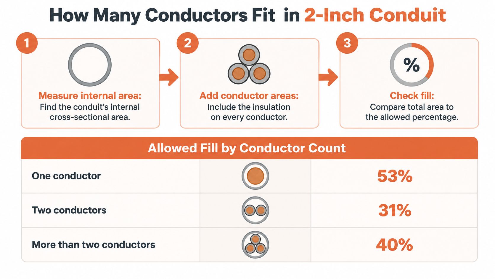
Four steps that keep the BOM honest
- Confirm the raceway and its internal area. Use NEC Chapter 9, Table 4 for the exact article, then check the maker's sheet. A rigid PVC dimensional sheet from Westlake Pipe puts Schedule 40 near an internal diameter of 2.067 inches, about 3.35 square inches, and Schedule 80 near 1.881 inches, about 2.78 square inches. EMT is close to Schedule 40 but not identical. Do not paste a PVC area onto an EMT line without opening Table 4 for Article 358.
- Apply the fill percentage to that area. At 40%, Schedule 40 screens at about 1.34 square inches and Schedule 80 at about 1.11 square inches. These are screening numbers. They are not a substitute for the adopted Chapter 9 tables or a local amendment.
- Add insulated conductor areas from Chapter 9, Table 5. Use the insulation type on the drawing, THHN, THWN, XHHW, or whatever is specified. Do not substitute a different insulation because the copper size matches.
- Compare and move up a trade size if the sum exceeds the permitted area. Also check pulling tension, sidewall pressure, bend count, and box entries. A legal fill can still be a bad pull.
A worked example, then the schedule trap
The Steel Tube Institute's example is the cleanest way to see the method. Three THWN conductors with a combined area of 0.4171 square inches need a raceway whose 40% area is at least that large. The table comparison lands on 1-1/4-inch EMT as the minimum, not 1 inch. The same arithmetic on a crowded feeder tells you whether 2 inch is enough, or whether you should step to something like 4 inch conduit when the bundle, the bends, and the pull length all stack up.
A 2-inch Schedule 80 run has less permitted area than a 2-inch Schedule 40 run with the same wire. If someone "upgrades" the schedule for abuse protection after the fill was approved, rerun steps 1 through 4. The wire package that passed can fail without a single conductor changing.
Edge cases that rewrite the answer
Short nipples can use a different allowance than a full run. Cable assemblies are not the same calculation as individual conductors. Equipment grounding conductors count toward fill. Multi-conductor cables, derating, and jam ratio sit beside the percentage, not instead of it. Approve the raceway article and the manufacturer data before the 2 inch conduit line on the BOM is released.
Ampacity Adjustments When Conduit Carries Many Conductors
A raceway size does not assign ampacity. Heat does. When several current-carrying conductors share a 2 inch conduit, each one runs warmer than it would alone, and the code cuts the allowable current before you ever look at the breaker.
Count-based adjustment
NEC 310.15(C)(1) applies an adjustment factor to the base ampacity once you have four or more current-carrying conductors. Confirm the table in the edition your authority having jurisdiction has adopted. The factors practitioners use from that rule are:
| Current-carrying conductors | Adjustment factor |
|---|---|
| 4 to 6 | 80% |
| 7 to 9 | 70% |
| 10 to 20 | 50% |
| 21 to 30 | 45% |
| 31 to 40 | 40% |
| 41 and above | 35% |
Say a feeder or a control bundle puts twelve current-carrying conductors in the raceway. That count sits in the 10-to-20 band, so the factor is 50% of each conductor's base ampacity. Apply that cut first. A conductor that looked fine at its table ampacity may need the next size up, or the bundle may need to be split across two raceways.
Temperature is a second multiplier
Ambient correction under NEC 310.15(B) is separate. A hot mechanical room, a rooftop, or a run beside process piping does not get absorbed into the count factor. You multiply the base ampacity by the count factor and by the temperature correction for the insulation and the ambient. Order matters less than doing both. Skipping either one overstates what the wire can carry.
Neutrals that carry only unbalanced current, and equipment grounding conductors, are often excluded from the current-carrying count. A neutral on a nonlinear load may not be. Those exceptions live in the adopted text and in local amendments, so count conductors from the one-line, not from memory of a prior job.
A conduit can pass the fill limit and still force a derating that the panel schedule never allowed for. Run fill and ampacity in the same review, on the same conductor list.
EMT, PVC, RMC, IMC and HDPE Compared for 2-Inch Runs
Wall thickness and the way the joint is made decide weight, labor, and where the raceway belongs. Trade size does not. Pick the article that matches the room, the soil, or the abuse, then size the bore.
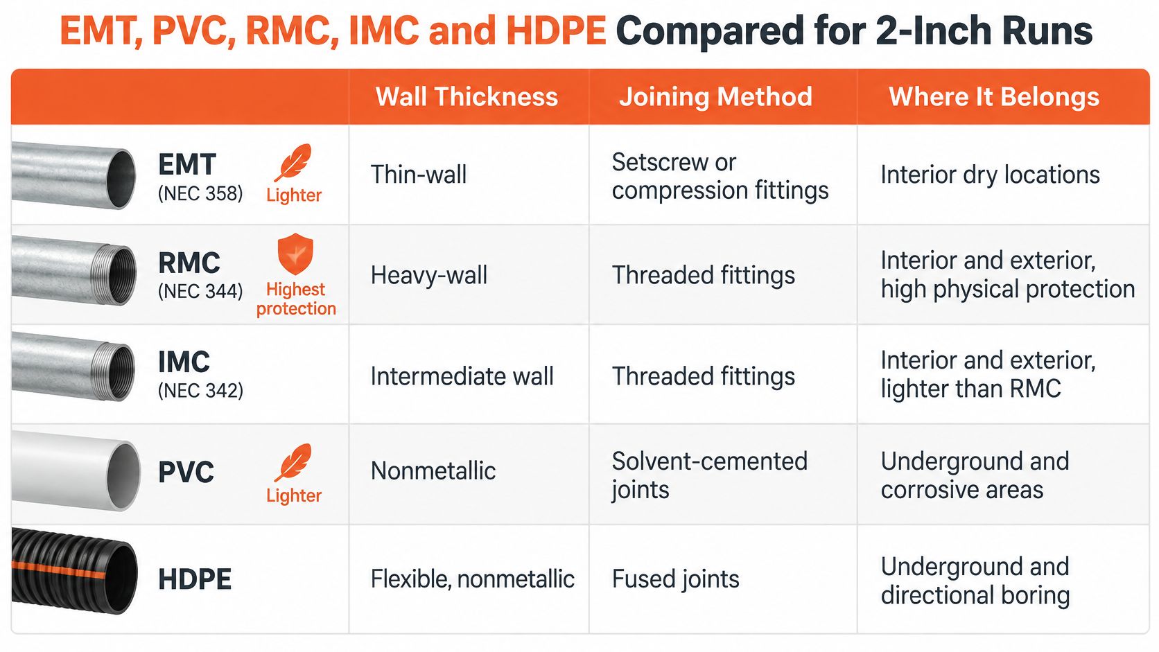
| Type | Wall and joining | Best fit for 2-inch | Main limitation |
|---|---|---|---|
| EMT | Thin-wall steel or aluminum, setscrew or compression fittings | Interior commercial and light-industrial runs | Limited physical protection |
| Rigid PVC | Nonmetallic, solvent-cement joints | Underground and corrosive areas | Needs protection and expansion planning above ground |
| RMC | Thick-wall, threaded | Outdoor and high-abuse industrial areas | Heaviest option; requires power bending |
| IMC | Thinner than RMC, threaded | Where RMC protection is needed with less weight | Threading required |
| HDPE | Nonmetallic, listed joining method | Underground and directional bore | Not a fit for exposed runs without added protection |
| Liquid-tight flexible metallic | Flexible metal with listed fittings | Motor and equipment connections | Not a rigid raceway |
EMT (Article 358) is the fast interior choice. Setscrew fittings are common in dry commercial work. Compression fittings earn their place where the listing or the spec calls for them. It is a poor pick where forklifts, weather, or corrosive washdown can reach the tube.
Rigid PVC (Article 352) solvent-cements and shrugs off a lot of chemical exposure underground. Above grade it needs physical protection where damage is likely, plus expansion fittings when the run sees a real temperature swing. It is not a grounding path.
RMC (Article 344) is the heavy, threaded answer for outdoor and high-abuse industrial areas. You will want a power bender or factory elbows at this size. IMC (Article 342) is also threaded and is used where RMC is permitted, with less weight to hang and to pull. A side-by-side of those metal systems is worth reading before you default to the heavier stick: EMT versus rigid conduit.
HDPE (Article 353) belongs in trench and directional bore, joined by the method the listing names. Do not leave it exposed and call it equivalent to RMC. Liquid-tight flexible metallic conduit (Article 350) is a whip to a motor or a skid, not a 200-foot feeder.
Two jobs, two answers
A 200-foot indoor feeder in a dry warehouse, with limited physical damage and a straight rack, is an EMT job unless the spec says otherwise. Labor stays down, and compression or setscrew couplings match the listing. The same nominal size as a riser on an exterior pole is a different product. There you want RMC, IMC, or Schedule 80 where the code requires a damage-resistant raceway, threaded or listed for that exposure, with a transition fitting back to whatever is buried.
The table is a starting point. The controlling pair is the code article and the environment on that segment of the route.
Where 2-Inch Conduit Is Used and What Limits Its Location
A 2-inch trade-size raceway can serve a feeder, underground lateral, pole riser, or large control and instrumentation run. The order line is incomplete until it identifies the raceway type and the conditions along the route. Where the run ends at metering equipment, coordinate the raceway route with the gear layout. This guide to planning electricity sub meter installation can help frame that coordination.
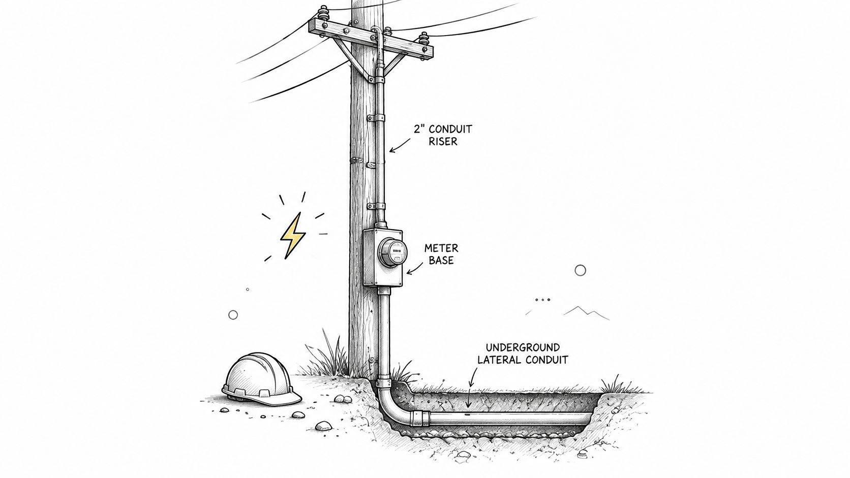
What OSHA requires on a construction site
OSHA's construction wiring-method requirements are in the construction standard for wiring systems. For pole risers, the standard specifies suitable raceway protection for conductors emerging from the ground. RMC, IMC, PVC Schedule 80, or an equivalent must extend from the ground line to at least 8 feet above finished grade, and metallic enclosures must be grounded. Check the applicable standard and adopted code for the installation; do not treat a general-purpose raceway choice as sufficient for every location.
One route, three products
Consider a lateral leaving a pad-mount, crossing a yard, rising on a wall, and entering a switchboard room. The nominal trade size may remain 2 inches, but the product should change where exposure changes.
- Underground: PVC suits a buried section where soil and corrosives can affect bare steel. Confirm the burial method against Article 352 and the burial table in the adopted code.
- At the riser: Use Schedule 80, RMC, or IMC where physical damage is a concern, and carry the raceway to the height the applicable rule requires.
- Inside the building: EMT or another permitted metal raceway may suit the interior section. Use a listed transition, and maintain the required bonding path across the change from PVC.
Classified locations impose a separate selection requirement. The equipment and wiring method must be approved for the specific classification, or use the applicable intrinsically safe approach. Match fittings, seals, and approval markings to the area. A fitting marked 2 inches is not automatically approved for a classified location.
The authority having jurisdiction, adopted code, and environmental classification govern the final selection. Specify the raceway type for each segment, not just “2-inch conduit,” so substitutions do not erase the protection the route requires.
Fittings, Couplings and Expansion Hardware for 2-Inch Runs
The fitting follows the conduit, not the other way around. A 2-inch coupling from the wrong system is a mismatch even when the number stamped on it looks right.
Match the joint to the material
Threaded RMC and IMC use threaded couplings. Terminations use locknuts and bonding bushings where the bonding path requires them. Do not mix a thread standard the hub was not cut for.
EMT uses setscrew or compression couplings and connectors the listing allows for that installation. A dry interior setscrew coupling is the wrong part in a wet or concrete-tight location.
Rigid PVC uses solvent-cement couplings, primer where the cement system requires it, and a listed transition fitting where plastic meets metal. That adapter is a BOM line, not a field invention.
HDPE uses the joining method listed for that product. If the submittal says fusion, a mechanical coupling from another system is not a silent substitute.
Expansion fittings belong on PVC that sees a significant temperature change, placed the way the manufacturer and the article describe. Guessing the gap at one end of a long roof run is how couplings crack in the first summer.
Hardware the pull will demand
Conduit bodies, LB, LR, LL, and T styles, plus pull boxes, are sized for the conductors and the direction change. Count them in the takeoff. Adding a body after the rack is hung usually means a coupling in a place you did not want one.
Grounding and bonding hardware on metal raceways has to satisfy the article, not just "touch metal." In a hazardous location, sealing fittings and the approved hubs go on the order with the conduit. Before release, confirm each fitting's listing matches the conduit type and the location, and that the size stays 2 inch unless a reducer appears on the drawing.
Substituting a fitting from a different manufacturer is a common way to get mismatched threads or a joint the listing does not cover. Check it against that maker's data before the release, not after the first failed pull.
Bend Limits, Threaded Joints and Pull Planning
Routing is limited by the total bend between pull points, not by how many elbows the CAD layer shows. A public conduit specification written to NEC requirements, the ADOT electrical conduit specification, states that bends between pull points must not exceed 360 degrees. Bends also have to avoid crimping or flattening, and they have to use no less than the applicable NEC radius. Field bends should use the longest practical radius.
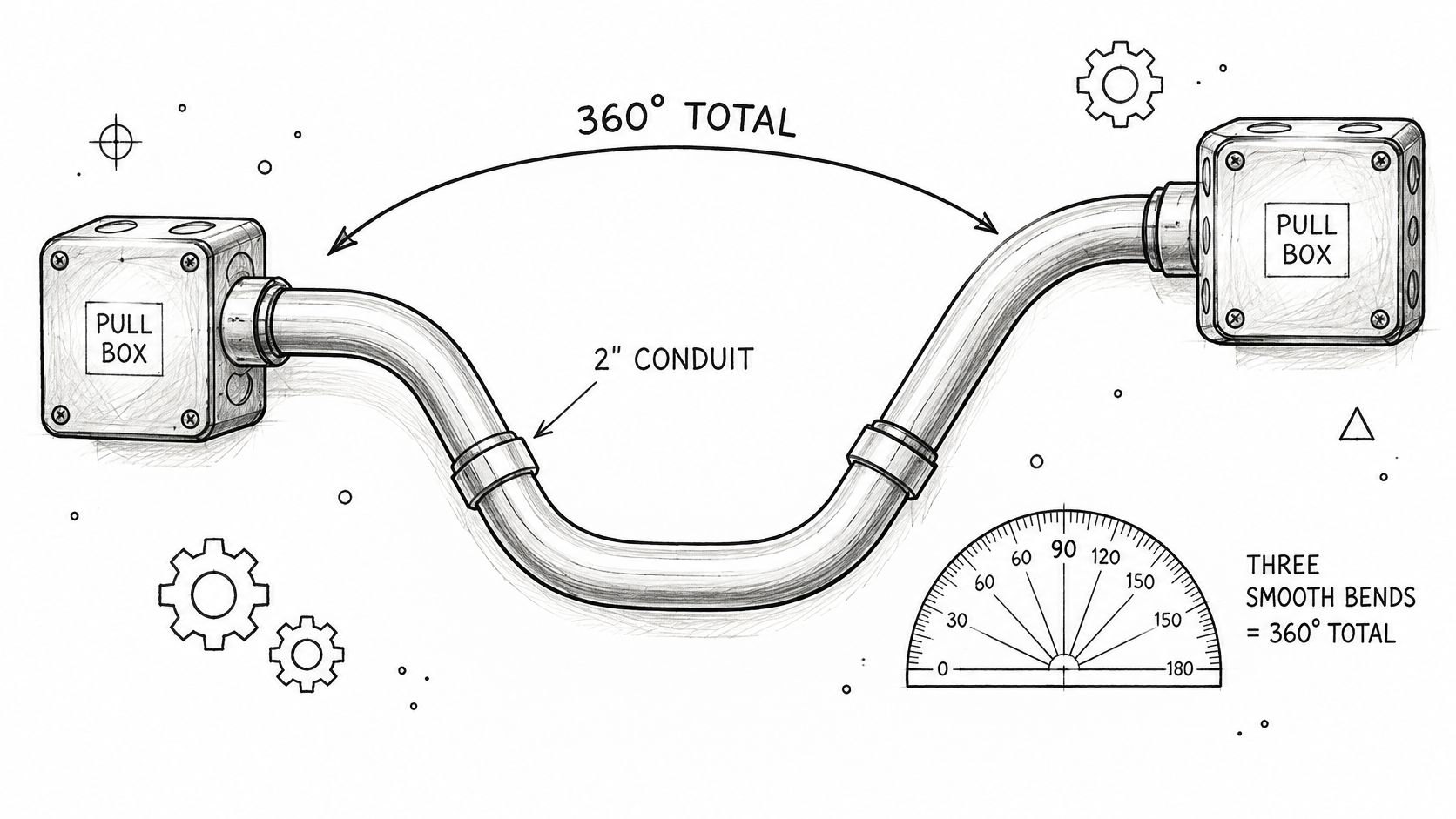
Two 90-degree bends plus one 180-degree sweep already consume the full 360 degrees. The next turn needs a pull box or a revised route. On large conductors in a 2 inch conduit, that limit is really about pulling tension and sidewall pressure. A legal-looking route can still skin insulation at the throat of a tight elbow. The same geometry shows up on device runs. Crews who avoid common CCTV installation mistakes already know that a camera whip full of elbows becomes a pull you cannot finish without a box.
Install in this order
- Plan the route and add the degrees between pull points. If the sum is over the limit, move a box now, while it is still a sketch.
- Cut PVC square and deburr every end. A knife edge inside a 2-inch stick will cut the jacket on the first pull.
- Bend to the bender chart for that material, using the longest practical radius. A factory long-radius elbow beats a field bend when the chart radius is hard to hit. Keep a 90 degree elbow conduit in the takeoff when the turn is structural, not a tweak.
- Make RMC and IMC threaded joints wrench-tight. In hazardous, classified locations, OSHA 1926.407 requires threaded conduit and wrench-tight joints, and a bonding jumper where making the joint tight is impractical. Outside those locations, bond the way the applicable NEC article and the fitting instructions require.
- Support the raceway to the spacing in its article. A 2-inch stick sags differently in PVC than in RMC. Use the article you installed.
- Put bodies, pull boxes, and long-radius elbows on the material list before the pull. They are not field substitutions after the truck leaves.
The failures that show up at inspection are predictable. Sidewall pressure on large conductors, insulation cut at a flattened bend, and a loose threaded joint in a classified area. Each one is cheaper to prevent on the takeoff than to open up after the wire is in.
Specifying, Verifying and Ordering 2-Inch Conduit
An order line that survives substitution names more than a diameter. Write nominal size, material, schedule or wall (Schedule 40 or 80 PVC, EMT, RMC, IMC, or HDPE), length (10-foot or 20-foot where that applies), listing and code article, fitting type, coating or finish, and whether a submittal is required. "2 inch conduit, gray" is how the wrong stick arrives.
A price benchmark, not a quote
In 2025, BuildGents unit-price data reported a median public-bid price of $31.00 per linear foot for 2-inch electrical conduit. The middle half of those bids ran from $20.00 to $48.75. That spread is bid scope and region, installed work rather than a stick price at a counter. Use it to sanity-check an estimate. Do not paste it into a purchase order.
Check the package before it ships
Before the BOM is released, confirm each of these. They catch the swaps that look harmless on a packing list.
- Material and schedule are named on both the spec and the quote, not implied by color or by a photo.
- Inside diameter, not the trade size, is the fill input, and the raceway article matches Table 4.
- Fill and ampacity adjustment are both checked against the adopted NEC edition and any local amendment.
- Total bend between pull points stays inside the limit, with boxes already on the list.
- The raceway matches the location, including any hazardous-location approval, seals, and markings.
- Fittings, bodies, supports, and pull boxes are in the takeoff at the same size, unless a reducer is drawn.
Set screw couplings and equipment lugs still have to be tightened to the values the listing expects. A short buyer-side read on how to compare torque screwdriver features keeps that last step from becoming "snug by feel."
When a substitute is offered
Do not accept "equivalent 2 inch" on the trade size alone. Review inside diameter and the fill effect, the listing and code article, fittings, grounding and bonding, bend radius, environmental rating, country-of-origin documentation, and submittal approval. If any one of those moves, the rest of the package has to be rerun.
ATEK Distribution can compare that BOM with the specification, flag approved alternates when a specified product is delayed, and collect the compliance documentation the project needs. Send the spec, the conductor schedule, and the BOM for a technical review. Availability and lead times get confirmed on that request. They are not promised from a catalog page.
ATEK Distribution helps contractors, engineers, and procurement teams source 2 inch conduit, fittings, and the raceway hardware that has to match the spec, including hard-to-find alternates and the paperwork that goes with them. If a 2-inch line on your BOM is short on schedule, listing, or fittings, send it over before the substitution hits the site. Start with ATEK Distribution and ask for a project-specific availability check.