The replacement switch is ready, but the swap has stalled. Its uplink disappears beneath the raised floor, neither end has a readable label, and the drawing doesn't identify the route. Someone now has to trace a live connection during a maintenance window that was supposed to involve equipment, not infrastructure.
That's the practical test for a structured cabling data center design: can the team change active equipment without rediscovering the cable plant? The hardest decisions aren't patch-cord colors. They're cross-connect locations, pathway capacity, media compatibility, and whether the installed trunks can support future bandwidth generations without another cable pull.
Structured cabling is standardized, documented permanent infrastructure that separates the building's cable plant from equipment connections. Instead of installing another dedicated route whenever equipment moves, technicians make controlled changes at accessible termination points.
Think of the installation as distinct layers:
Permanent cabling: Backbone and horizontal links that remain through equipment refreshes.
Cross-connects: Patch panels and distribution frames where technicians administer connections.
Equipment connections: Removable patch cords and equipment cords that accommodate operational changes.
In a data center, higher equipment density, frequent changes, and demanding uptime expectations make this separation particularly valuable. A tangled office closet is inconvenient. An unidentified production uplink can turn a planned replacement into an outage investigation.
Sales of structured-cabling products installed in data centers increased by almost 35% worldwide in 2024, according to BSRIA. That activity makes disciplined administration important from the first installation, not something to add after expansion.
RDE Technologies' resource on business network infrastructure cabling provides useful context for separating permanent infrastructure from device connections. Data-center engineers must extend that discipline into hierarchy, standards, media selection, pathways, redundancy, testing, and procurement.
Design priority: Make the next maintenance action predictable. A technician should know which panel, port, and cable record to use before disconnecting anything.
Data Center Cabling Hierarchy and Rack, Row and Zone Layouts
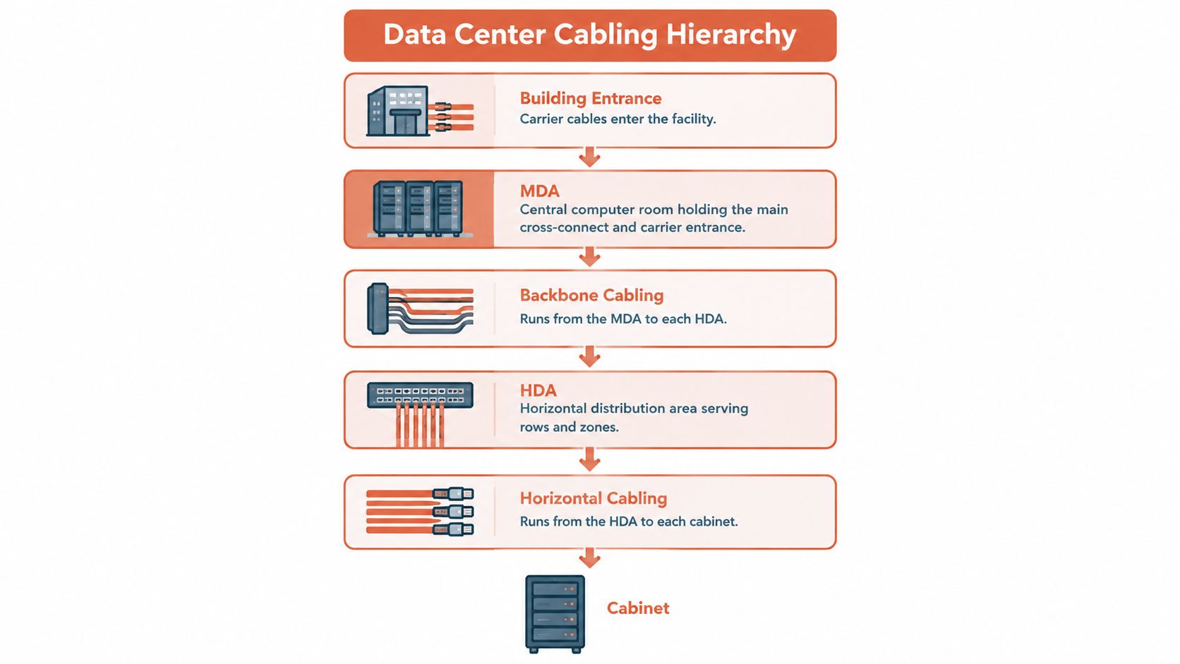
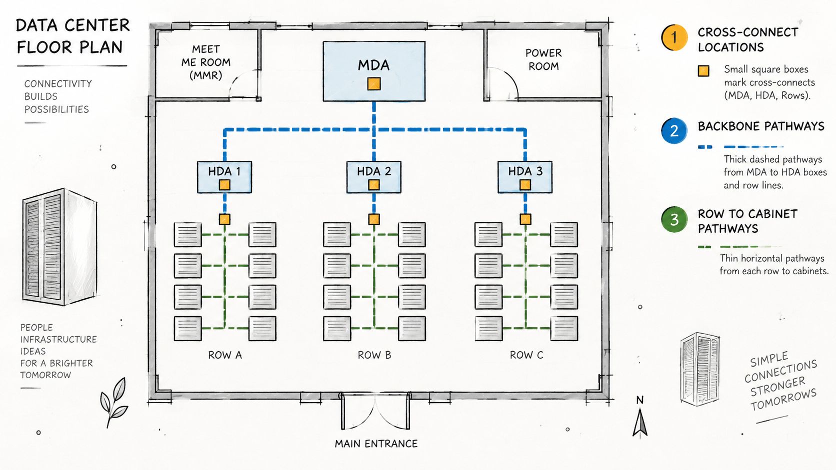
Trace the physical route from the building entrance to the cabinet. Carrier services reach the main distribution area, backbone cabling connects distribution locations, and horizontal cabling reaches equipment areas. These are physical administration spaces, not a requirement to use a particular logical switching topology.
Distribution areas in a standards-based data center
Distribution area
Typical location
Connects
Role in the design
Main Distribution Area (MDA)
Central computer room near the carrier entrance
Backbone to HDAs and external carrier cabling
Main cross-connect; highest fiber concentration
Horizontal Distribution Area (HDA)
Room or large zone, central to its EDAs
Backbone from MDA to horizontal links serving EDAs
Passive consolidation point; groups distribution toward equipment
Equipment Distribution Area (EDA)
Racks and cabinets
Horizontal cabling to equipment ports
Patch panels and cords serving equipment connections
A ZDA can consolidate distribution serving a group of rows, but it doesn't automatically reduce the number of required circuits. Don't treat a passive consolidation point as an extra switching location or assume it removes downstream cable requirements.
Choose the administration location deliberately
Rack-level patching keeps panels inside each cabinet and suits compact clusters. It also distributes administration across more locations. Row-level patching concentrates access at the row end or middle, with manageable local equipment connections. Zone-level distribution serves several rows from a shared location, trading centralized access against larger bundles and longer routes.
For a hypothetical end-of-row design, measure the actual pathway to the farthest cabinet, including vertical transitions and service routing. Check the fixed run against the 90 m permanent-link baseline, leaving the conventional 10 m cord allowance described in the University of Naples data-center cabling teaching document.
The TIA-942-C infrastructure white paper recommends at least two optical fibers for horizontal and backbone cabling. That minimum supports duplex arrangements and migration flexibility, but redundant service still requires appropriately designed independent links.
Centralized, labeled cross-connects let technicians isolate a segment or replace equipment without disturbing fixed cable. Reserve spare ports, document fiber allocation, and check cabinet working space using the dimensions and management provisions illustrated by Vericom VC5 Series network cabinets.
TIA-942 and ISO/IEC Standards Behind the Design
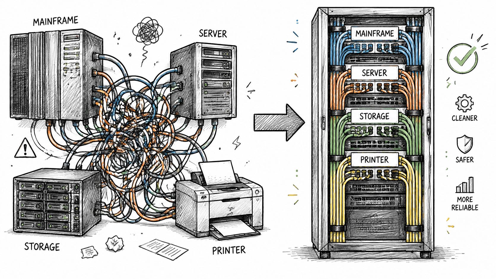
Data centers once accumulated proprietary point-to-point connections for mainframes, servers, storage, and peripherals. Those cables were difficult to identify and relocate, particularly beneath raised floors. A permanent, generic architecture replaced that equipment-specific approach with defined media, distribution areas, and administration practices.
As documented by Cabling Installation & Maintenance, ANSI/TIA-942 was published in April 2005, becoming the first standard from an accredited standards organization specifically addressing physical data-center infrastructure. Its foundational scope covered site space and layout, telecommunications cabling, tiered availability, and environmental considerations.
Use a coordinated standards set
TIA-942-C is the current edition used as this guide's reference, following Addendum 1, Addendum 2, TIA-942-A, and TIA-942-B. On an actual project, verify the edition specified by the owner rather than assuming a reference without a suffix means the latest publication.
Standards commonly referenced for data center cabling
Standard
Scope
How it is used
ANSI/TIA-942, edition C used here
Data-center spaces, pathways, cabling, reliability, and environment
Primary architecture reference; verify the project edition
Applicable ISO/IEC cabling standards
International cabling architecture and performance framework
Coordinate international specifications, link models, and acceptance requirements
For international projects, the engineer should identify the applicable ISO/IEC documents explicitly. Don't accept a supplier's statement of general ISO/IEC compliance as proof that a particular assembly meets the project's interface, performance, or testing requirements.
Specification check: A reference that says only “per TIA-942” leaves reviewers unable to identify the governing edition.
The standard establishes design requirements within its scope. Adopted codes and the authority having jurisdiction establish the applicable legal baseline. Procurement documents should identify both, resolve conflicts through the engineer, and retain manufacturer installation instructions as part of the installation package.
Copper and Fiber Distance Limits by Link Type
Distance references by data center link type
Link type
Media
Distance reference
Design note
Horizontal copper permanent link
Balanced twisted pair, Category 6A
90 m
Fixed-link allowance; retain cord capacity
Copper channel
Balanced twisted pair, Category 6A
100 m
Includes up to 10 m of patch and equipment cords
Short copper server links
Category 8
Below 30 m
Short data-center links, not a blanket horizontal replacement
Multimode fiber, internal links
Laser-optimized multimode
Roughly 100 m to 450 m
Application-specific; OM3 commonly specified around 150 m to 300 m
Direct MDA-to-EDA fiber
Laser-optimized multimode
Up to 300 m for applicable applications
Copper reference for the route is 100 m
Longer backbone fiber
Single-mode fiber
Transceiver-defined reach
Confirm the application and complete optical-loss budget
The copper allocations, OM3 references, and direct-route comparison above follow the Belden Data Center Guide; the broader multimode range and short Category 8 application are described by the Fiber Optic Association. These are design references, not universal reach guarantees for every Ethernet application.
Distinguish the fixed link from the operating channel
The permanent link generally excludes removable equipment and patch cords. The channel represents the complete connection used by active equipment, including those cords. A route can look acceptable when measured across the room yet fail certification because the fixed portion exceeds its allowance.
Measure cable along the installed route, not across the floor plan. Include tray diversions, cabinet drops, and managed slack. Check the governing standard's channel model and manufacturer guidance where cord construction, connection arrangements, or operating conditions affect the permitted configuration.
Category labels don't override application limits. Cat 6A is a sensible choice for appropriate horizontal copper applications; Category 8 addresses a different, shorter-link use case. Replacing a horizontal specification with a higher category can introduce a reach mismatch rather than an upgrade.
Budget optical loss before selecting assemblies
Fiber reach depends on more than distance. Each mated connector and splice consumes part of the optical-loss budget, while contamination or tight bends can introduce additional loss. Correct polarity is also necessary for transmit and receive paths to align.
For a short internal link, multimode may be economical if the intended optics support the route and connection count. For longer backbones or uncertain migration requirements, evaluate single-mode alongside the transceiver cost and service model. Neither choice eliminates the need to calculate loss.
Specify permanent-link length, channel length, fiber class, connector-loss allowances, bend-radius limits, and certification requirements. A purchase description containing only Cat 6A or OM4 doesn't tell the installer what constitutes an acceptable completed link.
Pathways, Space and Rack Density Planning
Start at the entrance and mark every cross-connect before drawing tray routes. Establish backbone paths between the MDA, HDAs, and rows, then size horizontal distribution to cabinets. Routing cable first and finding termination space afterward usually creates awkward drops and inaccessible panels.
Reserve usable space, not an unspecified allowance
Pathway drawings should distinguish installed cable from capacity reserved for future trunks. Show where that reserve exists, including bends, wall penetrations, tray transitions, and cabinet entries. An open straight tray doesn't provide useful expansion capacity if the next penetration is already crowded.
Keep data cabling coordinated with power conductors and cooling pipework. The separation method must follow the adopted code, engineered arrangement, and cable and raceway manufacturer instructions. Don't apply a universal separation distance without checking the installation conditions.
Cable mass matters as well as fill. Bundled copper and high-count trunks load supports, while entry angles can force cables below their allowable bend radius. For smaller supported branches, evaluate CADDY J-Hook options against cable loading, support spacing, fastening conditions, and manufacturer instructions rather than treating hooks as interchangeable with tray.
Make the cabinet maintainable when it's full
Top-mounted patch panels can simplify overhead entry; middle-mounted panels may shorten local cord routes but consume equipment space. Select the position against the populated rack elevation, not an empty cabinet photograph. Vertical managers must accommodate connected cords while preserving access to power supplies, fans, and removable equipment.
Facilities sign-off should address:
Structural loading: Tray, brackets, anchors, and their supporting structure suit the planned cable load.
Expansion access: Spare capacity extends through transitions and penetrations, not just open spans.
Cabinet serviceability: Doors close, managers remain accessible, and cord routing fits the approved channel model.
Have the facilities team review the route with the installer and designer. Their maintenance access requirements often expose conflicts that aren't obvious in a telecommunications-only drawing.
Designing Redundancy and Upgrade Paths for AI Density
The densest connector arrangement isn't automatically the best long-term plant. It can save panel space while making inspection, cleaning, and retermination harder. If technicians can't service a connection without disturbing neighboring circuits, nominal density becomes an operational liability.
The Ethernet Alliance white paper on AI infrastructure reports that AI data centers can require up to eight times more fiber density than traditional facilities, with back-end networks using 400G and 800G transceivers and moving toward 1.6Tb links. Those transitions make pathway and trunk decisions consequential well beyond initial commissioning.
Compare usable migrations, not installed strands
Use this project-planning metric:
Cost per usable upgrade path equals installed plant cost plus expected cleaning, inspection, and retermination labor, divided by the number of future link generations the pathways and trunks can support without new pulls.
Evaluate 8-fiber, 16-fiber, and higher-count connectivity against actual candidate transceiver interfaces and breakout arrangements. A higher strand count isn't automatically more reusable if connector presentation, polarity, or loss prevents the intended migration.
Consider competing designs. A minimal trunk installation with no route reserve costs less initially, but increasing fiber count later requires another pull and another disruption. A design with reserved trunk and tray capacity costs more upfront but may allow the next generation through panel or cassette changes.
Separate redundancy from spare capacity
Spare fibers provide restoration and expansion options. They don't provide route diversity when they occupy the same vulnerable cable or pathway. Route redundant links so a single damaged support, penetration, or maintenance action doesn't disable both.
Review wire and cable tray options against that diversity requirement, not just fill. Document polarity, fiber allocation, interface assumptions, and optical-loss budgets for each proposed migration.
Replacement also needs an exit strategy. When equipment retirement or a larger refresh requires taking infrastructure out of service, Reworx Recycling's guidance to plan a secure data center shutdown provides relevant decommissioning context. Keep reusable trunks identifiable, and separate equipment disposition decisions from decisions about retaining the permanent plant.
Testing and Documenting the Installed Plant
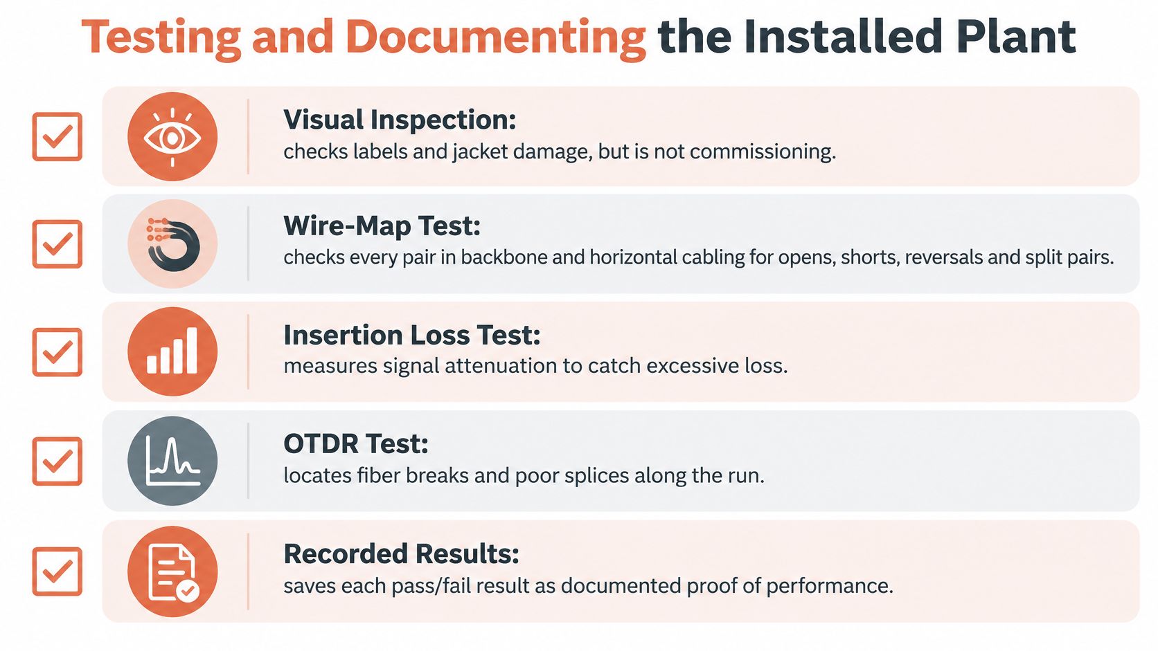
Visual inspection identifies damaged jackets, poor routing, and missing labels. It doesn't demonstrate transmission performance. Commissioning requires recorded field measurements against the specified acceptance criteria.
Use the checklist below as a workflow aid, with the contract test schedule controlling the required measurements.
Test the failure modes separately
The NECA/BICSI installation guidance identifies wire-map testing for all pairs in backbone and non-horizontal balanced twisted-pair cabling, with results recorded for every segment. For optical fiber, it identifies optical-loss test-set measurements of length, polarity, and attenuation.
Field tests and what each one catches
Test
What it measures
Failure it catches
Record kept
Wire map
All pairs in backbone and non-horizontal balanced twisted-pair cabling
Opens, shorts, reversals, and pair miswires
Result for every segment, tied to cable ID
Length
Installed cable length
Permanent link or channel over budget
Length per cable ID
Polarity
Transmit and receive orientation on fiber links
Crossed or reversed fiber pairs
Polarity result per fiber link
OLTS attenuation
Connector, splice, and cable loss
Link budget exceeded by dirty or poor connections
Measured loss per fiber link against budget
Inspect and identify: Confirm endpoint labels and physical condition before connecting test equipment.
Certify copper: Use the correct permanent-link or channel adapters and the specified category test limit. Wire map alone isn't full performance certification.
Measure fiber: Inspect and clean interfaces, verify polarity, and measure attenuation using the specified reference method.
Investigate failures: Use an OTDR where specified or useful for locating fiber events. It doesn't replace the required end-to-end OLTS acceptance measurement.
The following video provides additional installation context; use the project's test requirements for acceptance.
Deliver records facilities can use
Tie every result to a unique cable or fiber identifier. Retain native test files, test limits, reference settings, equipment details, and final passing results after remediation. A summary spreadsheet without the underlying measurements makes later investigation harder.
Hand over those records with as-built drawings, rack elevations, fiber allocations, and patching schedules at project close. The facilities team should be able to select a cable ID and retrieve its endpoints and acceptance result without tracing the installed route again.
Confirm the Cabling Bill of Materials Before You Order
A trunk and cassette can look compatible on a purchase order yet produce the wrong fiber presentation at the transceiver. Fixing that mismatch after installation can require replacement assemblies, revised patching, and another test cycle. Resolve interfaces before comparing supplier totals.
The bill of materials (BOM) should describe an operable system, not a collection of individually acceptable parts. Include the transition components, support hardware, management accessories, and test obligations that connect the headline items into a usable installation.
Review the complete connection
Use a connection schedule alongside the BOM:
Media and optics: Confirm fiber type or copper category against the intended application and complete link budget.
Connector system: Verify mating interfaces, connector gender where applicable, keying, polarity method, and cassette presentation.
Trunks and spare capacity: Reconcile installed assemblies with port allocations and the expansion capacity shown on drawings.
Patch cords: Select lengths from actual routing, including managers and equipment service positions.
Installation hardware: Include tray transitions, supports, cabinet entries, bonding provisions where applicable, and identification materials.
Ask suppliers for product submittals, compliance documentation, and installation instructions before release. Where the contract requires Buy American Act or Trade Agreements Act documentation, request project-relevant evidence rather than assuming the distributor's location establishes product eligibility.
Control substitutions and phased delivery
An alternate is acceptable only after the responsible reviewer checks it against the same interfaces, loss budget, installation constraints, and test requirements. Similar descriptions aren't enough. A connector substitution can change the number of mated interfaces or require a different polarity arrangement.
A sourcing partner can review the BOM against the specification, coordinate manufacturer availability, and identify candidates for engineering approval when items have long lead times. Material consolidation, kitting, and staged delivery also help installers receive complete work packages instead of cabinets without managers or trunks without the correct cassettes.
For a structured cabling data center project, request a quote against the approved connection schedule and specification, not just a parts list. Include required delivery phases, documentation, and acceptable-alternate procedures so procurement can compare complete offers rather than incomplete initial prices.
ATEK Distribution offers structured cabling and datacom products, BOM review, manufacturer coordination, and sourcing support for hard-to-find components and proposed alternatives. Visit ATEK Distribution to request a project-specific quote, and include your connection schedule, link requirements, compliance needs, and installation phases so the team can help assemble a coordinated procurement package.
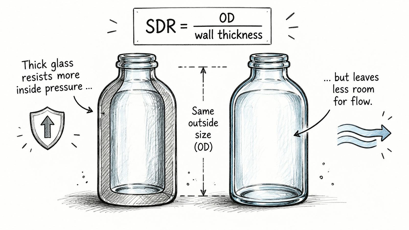
A 2 HDPE pipe is a nominal size, not a fixed bore. IPS PE4710 pipe at that size has an outside diameter of about 2.375 inches, and the SDR, which sets wall thickness, determines the inside diameter and pressure rating.
The popular advice is to order by nominal diameter and let the supplier sort out the rest. That's where substitutions fail. Two pipes can share the same outside diameter, fit the same trench, and still differ on pressure class, flow area, fitting compatibility, and potable water listing. If you're buying for water service, conduit, telecom duct, or a trenchless pull, the spec line decides whether the product passes. The label doesn't.
2-Inch HDPE Pipe Dimensions and Pressure Ratings at a Glance
At the same 2.375-inch outside diameter, a 2-inch IPS HDPE pipe can have different wall thicknesses, bores, and pressure ratings. The specification line, not the nominal size, determines whether a substitute fits the design. For temporary water systems, the Philadelphia Water Department temporary water specification permits PE4710 pipe at DR 9, rated 250 psi, or DR 11, rated 200 psi. Those are different pressure classes, not a single minimum for the size.
Reading the Table in Three Steps
Check the SDR or DR on the pipe marking and in the specification. Then compare its wall thickness and inside diameter with the approved product data. Finally, confirm the pressure rating and its temperature basis before approving a substitution.
2-inch IPS HDPE pipe by SDR, wall, bore and pressure
Standard dimension ratio (SDR)
Wall thickness (in)
Inside diameter (in)
Pressure rating (psi)
SDR 7
0.339 calculated
1.697 calculated
333
SDR 9
0.264 calculated
1.847 calculated
250
SDR 11
0.216 to 0.219
1.937 to 1.943
200
SDR 17
0.140 calculated
2.096 calculated
125
The SDR 7 and SDR 9 dimensions are calculated from a 2.375-inch outside diameter, using wall thickness = outside diameter ÷ SDR and inside diameter = outside diameter − 2 × wall thickness. The SDR 11 range follows those same calculations using its listed wall range. SDR 17 is calculated from the same OD basis. Confirm all dimensions against the manufacturer's table before ordering. Pressure ratings are commonly quoted at 73°F and must be derated for higher service temperatures.
Caveats That Change an Order
Published dimensions can vary by product and manufacturer. Use the exact submittal for the pipe being approved, particularly when fusion fittings or mechanical couplings must match the pipe's outside diameter and pressure class.
Practical rule: Confirm the SDR first. The bore value only applies to that wall thickness.
The municipal specification's DR 9 and DR 11 ratings apply to its stated requirements. Other owners may specify a different class for the same nominal size. Temperature also affects the allowable pressure, so a rating at 73°F does not automatically apply unchanged in warmer service.
A purchase request that says only “2-inch HDPE pipe” leaves the SDR unresolved. That choice changes the bore, wall, pressure capacity, surge tolerance, and fitting compatibility. Specify the required SDR and pressure class, then verify the dimensions against the approved product data.
Why One Nominal Size Hides Several Different Pipes
A 2-inch HDPE pipe is several products, not one. The nominal size does not establish the bore, wall thickness, or pressure capacity. SDR, the ratio of outside diameter to wall thickness, changes all three while the outside diameter stays the same. With a 2.375-inch OD, a calculated SDR 11 wall is about 0.216 inch, leaving an approximate 1.943-inch bore. At SDR 17, the calculated wall is about 0.140 inch, leaving an approximate 2.095-inch bore. These are geometric estimates; use the product submittal for manufacturer-specific dimensions and ratings.
More Bore Is Not Free
A larger bore can increase flow area, but the thinner wall also changes the pressure rating. One listed 2-inch SDR 11 PE4710 product is rated at 200 psi; its listing and linked dimensions are available from SiteOne's SDR 11 pipe product data. Do not assume that rating applies to another SDR or manufacturer. Check the specified product's rating against operating and surge pressures, with the applicable temperature basis.
The Sizing System Trap
A metric pipe described as 63 mm OD measures about 2.48 inches across, unlike 2-inch IPS pipe at 2.375 inches. The JSK 2-inch HDPE listing illustrates why the sizing system matters. Confirm IPS or metric, actual OD, SDR, and fitting compatibility before approving a substitute.
The same nominal label can mislead when comparing raceways. Check the usable opening of the 2-inch PVC conduit, not just its trade size.
Electrical conduit requires its own dimensional check. Southwire lists a construction with a 2.375-inch OD and 0.261-inch wall. Those dimensions yield an approximate 1.853-inch bore, not 1.917 inches. Use the listed construction and applicable conduit standard for fill and pulling checks, as shown in the Southwire cable specification. Pressure pipe is not an automatic conduit substitute; verify its listing against UL 651A and NFPA 70.
Reading PE80, PE100 and PE4710 Resin Designations
The resin designation reflects the minimum required strength, or MRS, that the material is classed for. It doesn't set the pressure rating by itself. The rating combines material strength, a design factor, and the SDR, so two pipes at the same SDR can carry different ratings if the resin class differs.
PE4710 is the ASTM D3350 designation for a PE100-class resin. That means PE4710 and PE100 sit in the same strength class when the material meets the designation. It doesn't mean every product described loosely as PE100 automatically satisfies a specification that calls out PE4710, a named standard, and traceability.
PE80, PE100 and PE4710 designations for a 2-inch order
Designation
Minimum required strength (MRS)
What it means for a 2-inch order
PE80
8.0 MPa
Lower strength class; the pressure rating at a given SDR is lower than PE100, so never substitute without re-rating
PE100
10.0 MPa
Higher strength class; the rating still depends on the chosen SDR, so confirm it against the manufacturer table
PE4710
10.0 MPa class
The designation named in the 2-inch temporary water specification; confirm it on the resin certificate
The pressure rating still depends on SDR and temperature basis. A stronger resin doesn't rescue an SDR that's too thin for the operating and surge pressures. A thicker wall doesn't fix a resin certificate that doesn't match the specified designation.
Grade Alone Does Not Finish the Design
The Plastics Pipe Institute identifies pressure rating or class, buried-pipe design, and thermal design as core considerations for polyethylene piping systems, as set out in its HDPE Handbook purchase and publication page. Those three checks explain why a buyer can't approve an alternate on resin name alone. Burial conditions and temperature can control the selection even when steady pressure looks acceptable.
Compare two order lines. "PE4710, DR 11, 200 psi, IPS, AWWA C901" can be priced, submitted, and checked. "PE100 2-inch pipe" can't. The second line leaves out sizing system, SDR, pressure class, temperature basis, governing standard, and fitting requirements.
Grade tells you the strength class of the resin. It doesn't prove compliance for the service.
Keep material grade and compliance separate in review. NSF/ANSI 61 concerns contact with potable water and doesn't prove the resin grade. Ask for the resin certificate and traceability records alongside the dimensional table, pressure class, and listing documents. If a supplier proposes PE80 where PE100 or PE4710 was specified, require a re-rating at the actual SDR and temperature before anyone treats it as an equal.
Water, Conduit, Telecom and Trenchless Applications for 2-Inch HDPE
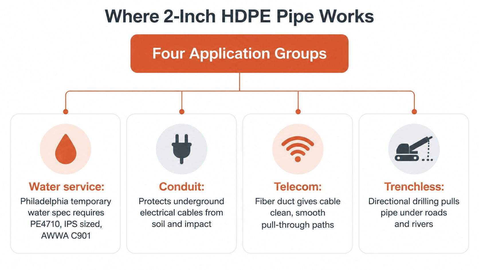
A 2-inch HDPE pipe is several products, not one. Pipes with the same nominal size can have different bores, walls, pressure ratings, and approved uses. The application sets the governing specification, so check service, sizing system, SDR, standard, and joining requirements before approving a substitute.
The diagram groups four applications that purchasing teams often see together on early bills of material.
Water Service
A Philadelphia temporary potable-water specification pairs PE4710, IPS sizing, AWWA C901, and NSF/ANSI 61 with either DR 9 at 250 psi or DR 11 at 200 psi. Fittings must be rated at least equal to the selected pipe. The SDR-to-pressure pairing matters: a DR 11 product rated at 200 psi does not meet a requirement for DR 9 at 250 psi, but it may comply where the specification allows either pairing.
Review the pipe and fittings together. A lower-rated fitting limits the pressure rating of the assembled system, even if the pipe itself meets the listed class. Submittals should identify both ratings on the same basis.
Electrical Conduit
UL 651A defines HDPE conduit as a rigid nonmetallic raceway for wires and cables under NFPA 70. Its normal ambient application is 50°C (122°F) or lower, according to the UL 651A standard listing on ANSI Webstore. The standard covers Schedule 40, Schedule 80, EPEC-A, EPEC-9, EPEC-11, and EPEC-13.5 constructions. Specify the construction, not only the nominal trade size.
For a buried feeder, the listing summary permits wiring rated up to 90°C (194°F) when the conduit is directly buried or concrete-encased outside buildings. Aboveground use requires encasement in at least 2 inches (50 mm) of concrete. Check installation method and cable temperature rating; the trade size alone establishes neither.
Conduit substitutions also require more than a bore comparison. For larger runs, the same checks apply when comparing 4-inch conduit: construction, fill, encasement, and temperature basis must suit the installation.
Telecom Duct and Trenchless Work
Telecom and communications duct requirements often come from the owner or utility. Before release, confirm the governing specification, duct size, pull-line requirements, and bend requirements. A product can match a generic dimensional description and still fail an owner's requirements for pulling or identification.
Trenchless installation adds loads that ordinary service comparisons may miss. Directional drilling and pipe bursting impose pull or burst forces on the pipe and joints during installation. The engineer of record must account for installation stress when selecting SDR, wall, and joints. A catalog match on nominal size is not a substitute for that review.
Governing references and checks by 2-inch HDPE application
Application
Governing reference
Checks before approval
Potable water service
AWWA C901 and NSF/ANSI 61
PE4710, IPS sizing, specified DR-to-pressure pairing, NSF/ANSI 61 listing, fittings rated at least equal to the pipe
Electrical conduit, buried or encased
UL 651A and NFPA 70
Normal 50°C ambient rating; 90°C cable rating only for direct-buried or concrete-encased use outside buildings
Electrical conduit, aboveground
UL 651A and NFPA 70
At least 2 inches of concrete encasement; confirm listed construction and temperature basis
Telecom and communications duct
Owner or utility specification
Confirm governing standard, duct size, pull-line, and bend requirements
Trenchless installation
Engineer of record and owner specification
Select SDR and wall for pull or burst loads; confirm joint method and tensile limits
Use the project's governing document to assess each application. Different owners can approve different products for similar work, and a nominal size cannot identify the correct specification.
How to Join 2-Inch HDPE Pipe in the Field
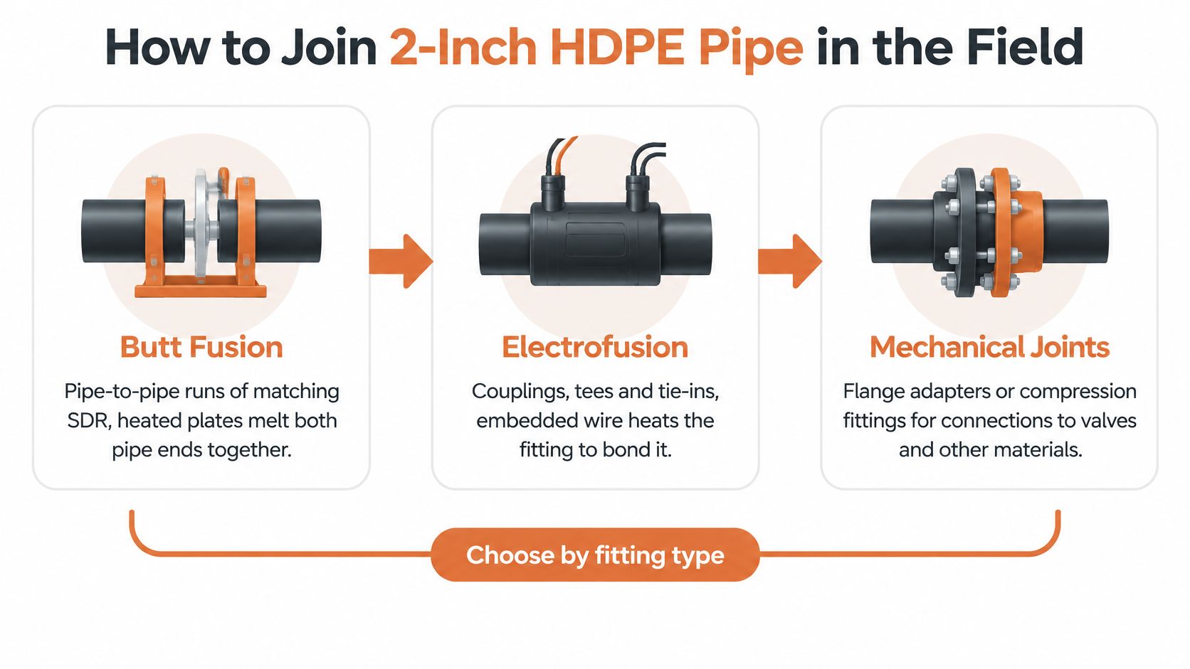
There are three joint families to sort before material arrives. Butt fusion suits pipe-to-pipe runs of matching SDR. Electrofusion suits couplings, tees, and tie-ins. Mechanical joints, such as flange adapters or compression fittings, suit valves, metallic pipe, and connections that can't be fused.
The three options are easiest to compare by fitting type.
Fusion isn't a preference you state casually. Many specifications require field assembly by butt fusion, with electrofusion where appropriate, and require the completed joint to have strength equal to or greater than the pipe. One detailed specification gives butt-fusion conditions of about 400°F, an optimum of 425°F, a maximum of 450°F unless the manufacturer directs otherwise, and 75 psi interfacial fusion pressure, as documented in the HRSD HDPE pipe and fittings specification.
Butt Fusion Procedure in the Field
Confirm match: Verify pipe SDR, outside diameter, and fitting compatibility before heating anything.
Confirm qualification: Verify the technician and machine are qualified for the pipe size, method, and equipment being used.
Clean and clamp: Clean the ends, clamp them, and check alignment so the joint doesn't start misaligned.
Face both ends: Face to a clean surface suitable for heating and fusion.
Heat to procedure: Heat to the specified temperature for the specified time under the manufacturer procedure.
Join and hold: Bring the ends together at the specified interfacial pressure and hold until cool.
Inspect and log: Inspect the bead and record the joint for traceability.
Pressure test: Test the completed work per the specification before acceptance.
That sequence is a summary for planning and submittal review. The manufacturer procedure governs the actual work, including heating, changeover, pressure, and cooling controls.
The video below helps crews visualize the handling sequence before they review the written procedure for the specific machine and fitting system on site.
Public works requirements also restrict fusion to formally trained and currently qualified technicians, with qualification tied to method, pipe size, and equipment. Request qualification records, fusion logs, machine capability information, and the test plan with the submittal. Don't accept a generic statement that the pipe is fusion compatible as proof the joint will pass.
Advantages and Limits Engineers Weigh Before Choosing HDPE
Most buyers start with hydraulics. Engineering guidance for gravity flow at the same internal diameter reports that PE pipe can provide approximately 44% greater flow capacity than concrete or clay pipe, reflecting Manning-equation behavior rather than a universal guarantee, according to the Plastics Pipe Institute hydraulic design advisory for pipe bursting.
That comparison doesn't finish a 2-inch calculation. Fittings, valves, entrance losses, elevation change, surge, and actual inside diameter may dominate, especially because SDR selection changes the bore. Use manufacturer dimensional data and a documented hydraulic method for the actual system.
Continuous fused bore: Butt-fused or electrofused joints preserve the internal path when they're made and inspected correctly.
Flexibility: The material suits coiled supply, curved alignment within design limits, and trenchless installation methods.
Corrosion resistance: Polyethylene avoids the corrosion mechanisms that drive replacement in some metallic systems.
Long-term pressure basis: Material selection rests on validated long-term pressure performance and service-life design, not only on light weight.
Transient pressure still needs a separate check. HDPE flexibility can reduce water-hammer severity relative to rigid materials, but rapid valve closure and pump trips can still exceed the steady-state pressure rating. Comparing HDPE with options such as conduit in stainless steel makes the trade off clear. You're choosing between flexibility and corrosion behavior on one side and rigidity and different joining or protection expectations on the other.
Limits to Price Into the Decision
Temperature derating: Pressure ratings quoted at a reference temperature must be reduced for higher service temperatures.
Thermal movement: Expansion and contraction on long runs need design attention at terminations and connections.
UV exposure: Outdoor exposure needs protection or a product and installation method approved for that condition.
Conduit restrictions: Electrical use brings ambient temperature, cable rating, burial, and concrete encasement rules.
Repair method: Repairs may need fusion equipment or matched mechanical fittings rather than a simple universal coupling.
Choose HDPE where buried, flexible, or trenchless runs benefit from fused joints and corrosion resistance more than rigidity.
Confirm the Spec Before You Order 2-Inch HDPE Pipe
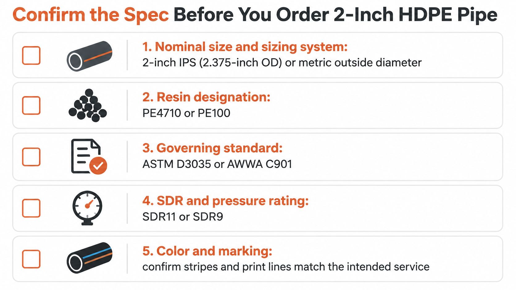
A complete RFQ prevents the most common substitution error. A product can fit physically and still fail pressure, certification, or submittal requirements. The checklist below turns a vague 2 HDPE pipe request into something an engineer can approve and a supplier can quote without guessing.
RFQ Checklist for the BOM Line
Size and sizing system: State nominal size and whether the outside diameter basis is IPS or metric.
Resin designation: State PE4710, PE100, or the exact grade required, with certificate requirements.
Governing standard: Name the ASTM, AWWA, UL 651A, or owner specification that controls.
SDR and pressure class: State SDR or DR, pressure class, and temperature basis together.
Potable listing: State NSF/ANSI 61 status where the line contacts drinking water.
Application conditions: For conduit, state ambient rating, cable temperature rating, burial method, and encasement.
Fittings: Require fitting type and pressure rating matched to the pipe's actual outside diameter.
Joining method: State butt fusion, electrofusion, or mechanical joining and the qualification required.
Submittals: Require dimensional tables, resin certificates, listings, and traceability records.
Alternate rules: State which changes need engineer approval before substitution.
The municipal example shows why item 4 can't be left blank. A specification listing DR 9 at 250 psi and DR 11 at 200 psi, with AWWA C901, PE4710, NSF/ANSI 61, and fittings rated at least equal to the pipe, is described in the Philadelphia temporary water systems specification from April 2025. Compare that with a line that only says "2-inch HDPE pipe." The first can be reviewed. The second invites every supplier to quote a different product.
Send the checklist with the RFQ and have the BOM line reviewed before the order is placed. Review should cover operating pressure, recurring and occasional surge, temperature, burial conditions, and water-hammer risk where they affect SDR selection. It should also confirm that an IPS product hasn't been confused with a metric or other sizing system product, and that conduit and raceway items for electrical work carry the right listing for the installation method. That review is faster before purchase than after pipe reaches the trench.
If a 2-inch HDPE line is holding up a package, send the full spec line, SDR, pressure basis, and fitting list to ATEK Distribution for BOM review, compliance documentation, and sourcing support on approved products or alternates. We'll help you check conduit, raceway, and hard-to-source electrical components against the project requirements and submit a request for quote with the details suppliers need to quote the right product the first time.
You're standing in a dispensing room with a submittal in your hand. The proposed fixture matches the lumen output, voltage, mounting pattern, and color temperature. It looks sealed and rugged. None of that tells you whether it belongs overhead.
That's where hazardous location lights specifications usually fail. Buyers compare lighting performance first and check the certification marking last, if at all. Reverse that order. Start with the classified area, read the complete label, and only then compare light output.
What Makes an Ordinary Light Hazardous in the First Place
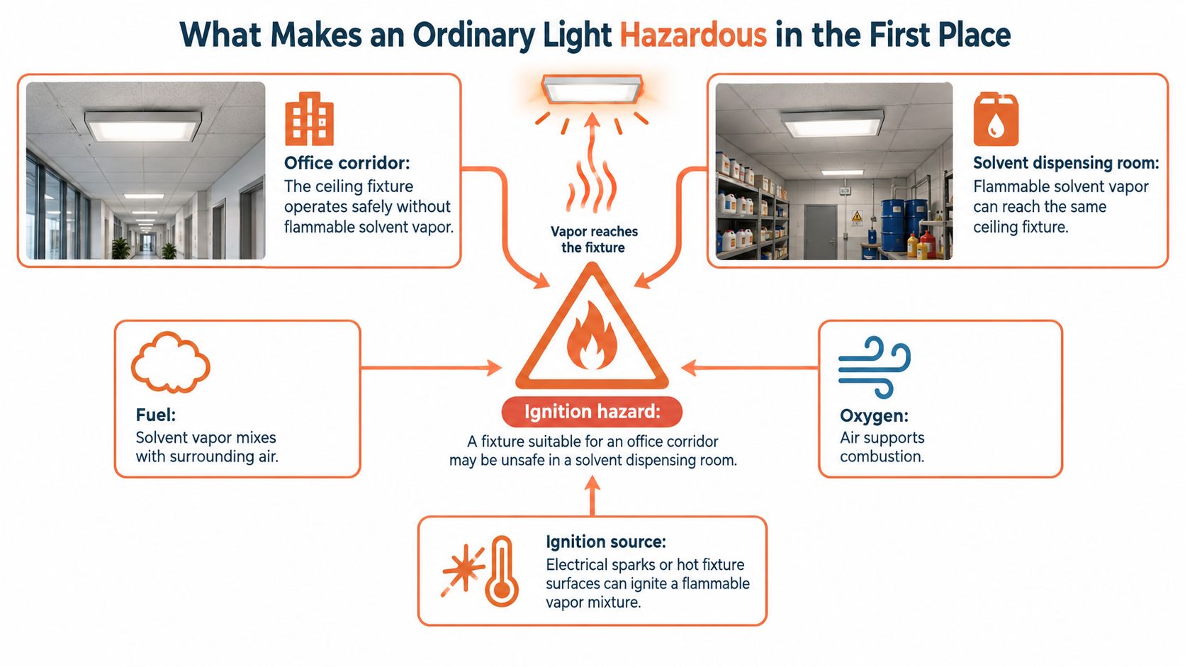
A standard ceiling fixture can operate safely in an office corridor and create an ignition risk in a solvent dispensing room. The fixture is unchanged; the surrounding atmosphere is not.
Combustion needs fuel, oxygen, and an ignition source. In a classified area, fuel may be flammable gas, vapor, or combustible dust mixed with air. Oxygen is already present, so the fixture must not supply the ignition source. A hot surface or electrical spark can provide one.
Three Ways a Fixture Can Ignite the Room
Hot surfaces: Lamp envelopes, drivers, and heatsinks can become hot. Dust collecting on a housing can raise its surface temperature.
Arcing: Switches, terminals, and connectors can spark during operation or if a fault occurs.
Breakage: A cracked lens or missing guard can expose hot or sparking parts to the surrounding mixture.
A hazardous location is an area where flammable gas, vapor, or combustible dust may be present in an ignitable concentration. A hazardous-location luminaire is evaluated against ignition-protection requirements for its intended area. A rugged housing or high light output alone does not establish that suitability.
Before comparing lumen output, voltage, or mounting options, check the fixture's classification and certification markings. Read the complete label and confirm that its ratings match the area's documentation. A lumen-matched substitute can still be unsuitable if its marking does not match; a Division 2 fixture, for example, must not be placed in a Division 1 area. Check the label's temperature rating against the specified ambient conditions, too, since a marking read at the wrong ambient temperature can lead to the wrong selection.
Classification answers two questions. What material creates the hazard? How likely is an ignitable concentration?
Class identifies the material. Class I covers flammable gases and vapors. Class II covers combustible dust. Class III covers easily ignitable fibers and flyings. Division identifies likelihood. Division 1 means ignitable concentrations can exist during normal operation. Division 2 means they're not expected during normal operation and would come from a leak, rupture, or equipment failure. The OSHA six-designation framework covering Class I, II, and III in Divisions 1 and 2 is the North American starting point, and a fixture suitable for one designation isn't automatically suitable for another.
Zones are the IEC-based alternative. Zones 0, 1, and 2 apply to gas. Zones 20, 21, and 22 apply to dust. Don't treat Zones as a one-to-one swap for Divisions. They use related logic, but the marking on the fixture has to match the system used on your drawings.
Classify the Room, Not the Whole Building
OSHA requires each room, section, or area to be evaluated individually rather than assigning one classification across an entire facility. A solvent dispensing booth shows why. The interior may be Class I, Division 1 while the area beyond a ventilated boundary is Division 2. One building, two different fixture requirements.
Field check: If you don't have a classification drawing for the current layout, you don't have enough information to release a purchase order.
Designation
Hazard material
Likelihood of ignitable concentration
Typical example area
Class I, Division 1
Flammable gases and vapors
Present during normal operation, repair, or frequent failure
Interior of a solvent dispensing or spray booth
Class I, Division 2
Gases or vapors in closed systems
Only after leak, rupture, or abnormal operation
Area around a sealed solvent pump
Class II, Division 1
Combustible dust
Normally in suspension or capable of ignition in normal operation
Interior of a grain elevator or flour mill
Class II, Division 2
Combustible dust
Not normally in suspension, accumulations may be present
Area outside a dust collector enclosure
Class III, Division 1
Easily ignitable fibers or flyings
Fibers handled or manufactured in the area
Textile or woodworking fiber processing area
Class III, Division 2
Easily ignitable fibers or flyings
Fibers stored or handled, not manufactured
Fiber storage room
Zone 0 (gas)
Flammable gas or vapor
Present continuously or for long periods
Inside a vessel or tank
Zone 1 (gas)
Flammable gas or vapor
Likely during normal operation
Area around a vent or filling point
Zone 2 (gas)
Flammable gas or vapor
Not likely, and short-term if it occurs
Area around a pump flange
Zone 20 (dust)
Combustible dust
Present continuously or for long periods
Inside a silo or hopper
Zone 21 (dust)
Combustible dust
Likely during normal operation
Area near a dust loading point
Zone 22 (dust)
Combustible dust
Not likely, and short-term if it occurs
Area near a dust collector filter housing
The common field failure is a Division 2 fixture installed in a Division 1 area. It usually isn't a deliberate shortcut. A process gets added, a booth gets moved, and the boundary changes while the installed fixture doesn't. Check the classification drawing against the fixture label before the material arrives, not during inspection.
Explosion-Proof and Intrinsically Safe Fixtures Compared
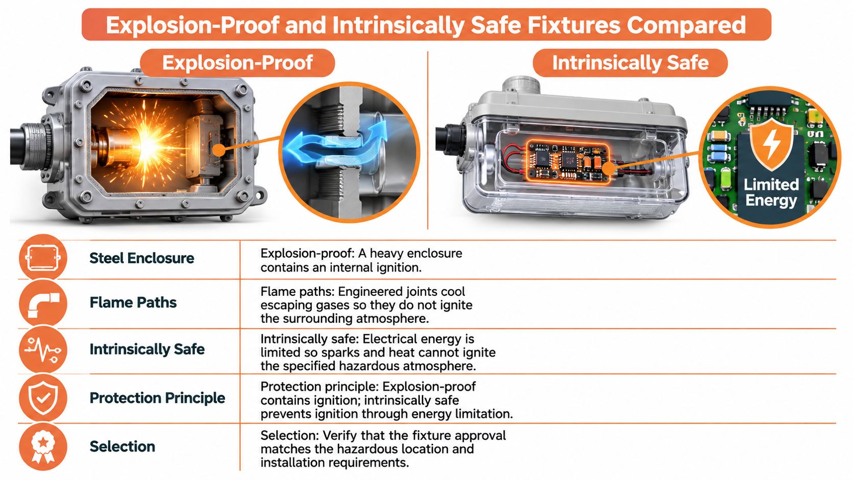
Two analogies clear up most of the confusion. An explosion-proof fixture is a heavy steel box. If ignition happens inside, the enclosure contains it and cools escaping gases through engineered joints so they don't ignite the atmosphere outside. An intrinsically safe circuit is closer to a low-energy battery toy. It limits electrical energy so a spark or hot surface can't ignite the surrounding mixture in the first place.
One contains ignition. The other prevents it by starving it of energy.
Explosion-proof is the common North American term. Flameproof, marked Ex d, is the IEC equivalent. Intrinsically safe systems depend on approved barriers, associated apparatus, and a control drawing. That dependency makes them common in instrumentation and low-power circuits, not in high-output general lighting where the luminaire needs substantial power.
The short video below is useful for seeing how enclosure construction and protection concepts differ in practice before you compare catalog claims.
Method
How it prevents ignition
Typical use
Watch-out
Explosion-proof (flameproof, Ex d)
Enclosure withstands internal explosion and cools gases through controlled joints
Fixed luminaires in Class I, Division 1 or Zone 1
Joints, threads, and seals must stay intact
Intrinsically safe (Ex i)
Limits energy so sparks and heat cannot ignite the atmosphere
Low-power circuits and instrumentation
Needs control drawing, barriers, and associated apparatus
Increased safety (Ex e)
Construction measures reduce arcs, sparks, and hot spots
Terminal enclosures and certain Zone 1 or 2 luminaires
Depends on certified construction, not field work
Purged or pressurized (Ex p)
Protective gas pressure keeps hazardous atmosphere out
Large enclosures and specialized housings
Requires purge controller, alarms, and interlocks
Nonincendive
Equipment cannot ignite atmosphere under normal conditions
Class I, Division 2 where listing allows
Valid only with listed equipment and wiring method
The Practical Verdict and the Dust Problem
For fixed luminaires in Class I, Division 1 or Zone 1, explosion-proof construction is the usual choice. In Division 2, nonincendive designs may work where the listed equipment and installation method allow it. Either way, field modification is the enemy. Damaged joints, missing threads, substituted seals, or a drilled enclosure can void the protection the listing depends on.
Dust changes the logic. In Class II and Zone 20 to 22 areas, protection depends on keeping combustible dust out and controlling surface temperature under dust layers. IEC markings use dust-protection codes such as Ex t, not flameproof codes. A gas-rated explosion-proof fixture does not establish Class II suitability. Put the cleaning schedule in the specification, because accumulated dust is part of the thermal problem.
Temperature Codes and Gas Groups on the Label
A T-code sets the highest surface temperature a fixture may reach under its rated conditions. The numbering runs opposite to what many buyers expect: T1 permits the hottest surface, while T6 permits the coolest. That rating is only useful when compared with the ignition temperature of the gas, vapor, or dust at the site.
For example, a site classified Zone 1, gas group IIA, T4 requires equipment suitable for Zone 1 and IIA, with a T4 or cooler temperature class. If the gas in the hazard inventory has an ignition temperature of 180°C, a T4 fixture rated for a maximum surface temperature of 135°C stays below that value. A T3 fixture, which can reach 200°C, does not. The mistake to avoid is treating 135°C as the point at which a surface becomes dangerous. It is the T4 maximum; the gas's ignition temperature determines whether that limit is suitable.
Gas groups provide another part of the match. IEC uses IIA, IIB, and IIC for gases. U.S. Class I practice uses Groups A through D. Check the fixture's marking against the specific gas or vapor in the site hazard inventory. A gas-group label is not a general approval for every gas.
Why a Correct Label Can Still Run Hot
The marked temperature class applies under specified ambient conditions. Check the fixture's certification and marking for its rated ambient range, then compare that range with the highest credible temperature at the installation. OSHA 29 CFR 1910.307 equipment marking requirements addresses equipment marking, but it does not establish a universal 40°C ambient basis.
A fixture can exceed the expected surface temperature if actual conditions differ from its rating. High ambient heat, dust on the lens or housing, thermal derating, mounting orientation, and nearby heat sources can all affect operation. Read the full marking against site conditions, not just the temperature recorded during a comfortable indoor visit. A cooler-rated LED may help limit surface temperature, but it does not replace the required Class, Division, or Zone certification.
Standards and Certifications Across NEC, UL, ATEX and IECEx
Start with the U.S. framework. NFPA 70, the National Electrical Code, covers division-based Class I, II, and III locations in Articles 500 through 504. Article 505 covers the zone-based Class I system. U.S. marine electrical rules point to those same NFPA 70 Articles 500 to 504 and Article 505 for hazardous-location equipment, which shows how central the NEC structure is to equipment suitability.
The edition in force isn't your choice. The adopting jurisdiction and the authority having jurisdiction set the edition and local amendments. Confirm both on each project before you lock a specification.
Equipment for Class I locations must be tested and listed by an independent laboratory against recognized standards. A manufacturer's unverified claim isn't enough. For luminaires, UL 844 is the long-established North American standard for electric luminaires in hazardous classified locations. UL 1598 for luminaires and UL 8750 for LED equipment are broader standards. They matter, but neither one by itself establishes hazardous-location suitability.
A fixture can be a well-built LED luminaire and still have no hazardous-location listing. Those are separate questions.
Standard or mark
Region or scope
What it covers
What to check
NFPA 70 Articles 500 to 504
United States, as adopted locally
Class I, II, and III division-based locations
Edition adopted by the authority having jurisdiction
NFPA 70 Article 505
United States, as adopted locally
Zone-based Class I locations
Zone marking matches the area
UL 844
North America
Electric luminaires for hazardous classified locations
Listing and classification marking on fixture
UL 1598
North America
Broader luminaire construction
Doesn't alone confirm hazardous suitability
UL 8750
North America
LED equipment safety
Doesn't replace hazardous-location listing
ATEX
European Union
Equipment for explosive atmospheres
Category and Ex marking matched to zone
IECEx
International scheme
Ex equipment certificates and conditions
Certificate, conditions, and temperature class
CCC Ex
China
Explosion-protection certification
Mark for installations in China
ECAS Ex
Eurasian region
Regional explosion-protection certification
Certificate and marking for installation country
International work adds separate pathways. A product may need ATEX, IECEx, CCC Ex, or ECAS Ex approval depending on the country and installation regime. Don't assume a North American listing travels.
The certification mark has to match the site's classification, temperature code, and electrical rating together. That discipline applies to the whole installed system, including raceway decisions you'll coordinate with items such as conduit sizing and routing for the wiring method. LED efficacy and enclosure construction are useful data. They don't establish suitability on their own.
Specification Data, Substitutions and Ordering Sequence
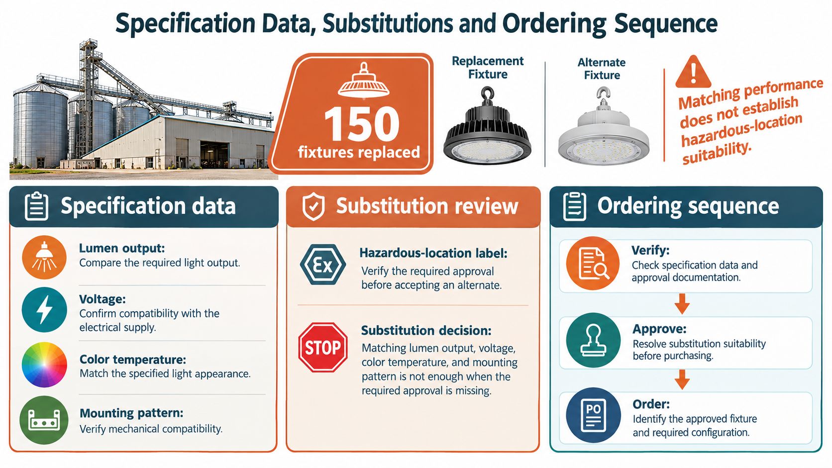
A grain handling building needs 150 fixtures replaced. A proposed alternate matches lumen output, voltage, color temperature, and mounting pattern. On a lighting schedule, it looks equivalent. Then someone reads the label and finds no Class II marking. That fixture isn't an alternate. It's a different product for a different hazard.
That's the substitution trap. Matching photometrics and mechanical fit doesn't establish hazardous-location equivalency. Under OSHA practice, equipment must be intrinsically safe, approved for the location, or demonstrably safe for the specific combustible hazard. The definition of the classes themselves, set out in OSHA 1910.399 hazardous location class definitions, makes the point plainly. A luminaire for combustible dust isn't automatically suitable for flammable vapor service, and the reverse is also true.
For Class I specifically, Division 1 covers locations where ignitable concentrations can exist during normal operation, during frequent repair or maintenance, or where equipment failure could release hazardous concentrations and create an ignition source at the same time. Division 2 covers materials normally confined in closed systems that could escape only through accidental rupture or abnormal operation, as described in the NFPA 497 Class I Division 1 and Division 2 area descriptions. That distinction is exactly why a Division 2 rating can't be stretched into a Division 1 space.
Data Every Specification and Submittal Must Contain
Don't release a fixture for pricing until these items are written down for each area.
Class and Division or Zone: State it for every area, not once for the building.
Gas or dust group: Match it to the actual materials in the hazard inventory.
Temperature code: Verify it against ignition temperatures, with margin for real conditions.
Ambient range: Include the highest credible temperature, not the design-day average.
Enclosure, mounting, and wiring method: Include sealing fittings and entry details.
Certification agency and complete marking: Require the full label text, not a summary line.
Control drawing: Required where intrinsically safe or associated apparatus applies.
Installation instructions and impact protection: Cover lenses, guards, and mounting hardware.
Service path: Confirm how lamps, drivers, gaskets, and seals get replaced without breaking the listing.
Requiring the manufacturer's certification label, control-drawing requirements where applicable, installation instructions, and evidence that the protection method covers the identified hazard protects you during alternate-product sourcing. If a submittal gives you lumens and wattage but not the complete marking, send it back. It's incomplete.
Installation Points That Belong in the Purchase Decision
A listed product can still become a noncompliant installation. Specify sealing fittings where the wiring method requires them, and drain or breather fittings where condensation is possible. Prohibit field modification of listed enclosures in the project documents, and make sure the installing contractor knows which entries, glands, and adapters are part of the listed assembly.
In Class II areas, schedule dust removal as maintenance, not housekeeping. Dust layers change thermal behavior and can become fuel. Log seal and gasket condition during those same visits. If a lens guard is damaged or a threaded joint won't engage fully, treat it as a protection failure and replace it with the same listed configuration.
The Buying Sequence That Catches Errors Early
Follow this order and most substitution problems surface before money is committed.
Collect the hazard inventory: Get materials and process conditions for each area from the owner or process engineer.
Classify each area: Work with the engineer and the authority having jurisdiction using the current layout.
Write the specification: Include the nine data items above for every classified area.
Verify candidate markings: Check each fixture's complete marking against its certificate or listing, model by model.
Request documents before award: Get submittals, instructions, and control drawings while you can still change course.
Evaluate alternates narrowly: Approve one only when marking, listing, and documentation match the classified requirement.
Plan replacements: Stock the same listed model and log seal, gasket, and dust-cleaning maintenance.
For government and institutional projects, collect compliance documents before award rather than after first delivery. Once fixtures are on site, a missing certification file becomes a schedule problem as well as a compliance problem.
Pre-order rule: If the label doesn't name your Class, Division or Zone, group, and temperature rating, the fixture isn't approved for your area no matter how closely the catalog performance matches.
Retrofit work deserves the same discipline as new construction. A project framed as an LED lighting retrofit for energy and maintenance savings still has to clear the classification, group, and temperature checks first. Savings from a fixture you have to remove after inspection aren't savings. Send the classified area schedule with your bill of material, require complete markings from every bidder, and resolve alternates on paper while the fix is still cheap.
If you're sourcing hazardous location lights and the submittals don't line up with your classification drawing, send the area schedule and bill of material to ATEK Distribution for BOM review, approved alternate evaluation, manufacturer coordination, and compliance documentation support. ATEK helps engineers, contractors, and procurement teams source listed fixtures and related distribution equipment without losing schedule to a bad substitution.
A panel schedule just landed with a service SPD, a distribution SPD, and a point-of-use unit. The three part numbers differ mainly by a Type mark and a large surge-current figure. That package can still be the wrong buy. Surge protection devices types name a permitted place and a test duty. They don't rank quality, and a bigger kiloampere claim doesn't finish the selection.
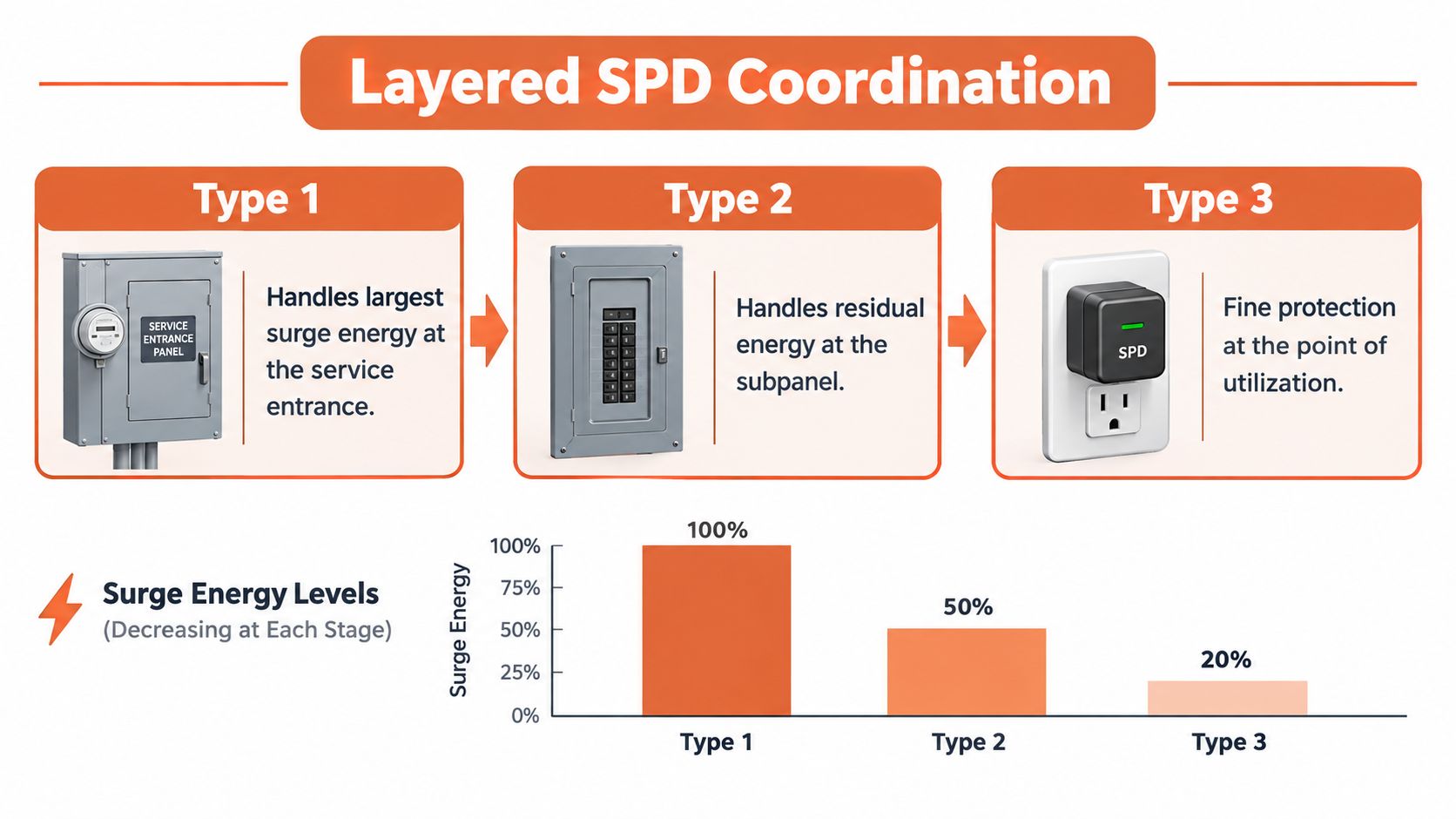
The service device may be marked only for the load side of the service overcurrent device. The downstream unit may clamp at a voltage the controls can't ride through. A communications line or a DC circuit may have been given an ordinary AC panelboard device. Work the checks in order. Match the mark to the location, the waveform to direct-lightning versus induced or switching duty, then continuous voltage, let-through, discharge current, and short-circuit rating. Stage the devices so the upstream unit takes the higher-energy event and the downstream unit cuts residual voltage near the load.
The submittal looks complete on a first pass. Three devices, three locations, three surge-current headlines. The service entrance calls for protection ahead of, or at, the main overcurrent device. The distribution panel calls for a second device. Sensitive controls call for something at the equipment. Procurement lines them up by ampere claim and treats the Type mark as a grade.
That comparison misses the failure modes that show up after the gear is on site. A device investigated only for load-side use can't fill a line-side service location just because the enclosure matches the switchboard. A branch device with a high surge-current number can still let through more voltage than a PLC, drive, or medical load will tolerate. An AC panelboard SPD on a PoE run, a PV DC circuit, or another DC power circuit is the wrong family of device, not a close alternate.
What the cut sheet didn't settle
The package fails for reasons that never appear in the surge-ampere column.
Location mismatch: The service unit's marking doesn't permit the side of the service overcurrent device where the one-line puts it.
Let-through mismatch: The downstream clamp voltage sits above the withstand of the control equipment, so the load still sees a damaging residual.
Circuit-family mismatch: Communications, photovoltaic DC, or another DC circuit received an AC power SPD.
Practical rule: The type name starts the selection. It doesn't finish it.
Those misses also show up as nuisance trips, burned equipment, and warranty arguments that trace back to power quality issues the SPD was supposed to limit. The rest of a defensible spec is a sequence, not a bigger catalog number. Confirm where the mark may be installed. Confirm whether the test waveform matches direct lightning current or induced and switching duty. Then compare continuous voltage, protection level, nominal discharge current, and short-circuit rating against the system in front of you.
Where Surge Protection Devices Types Belong
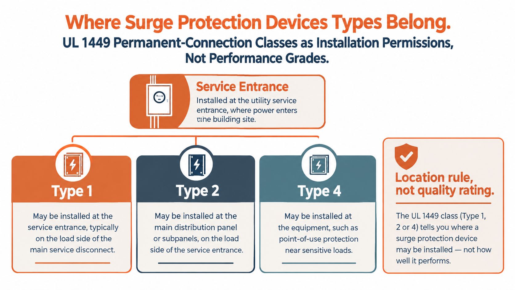
UL 1449 sorts permanently connected surge protective devices by where they may be installed. The classes are installation permissions, not performance grades. Place the mark on the one-line before anyone argues about joules or kiloamperes.
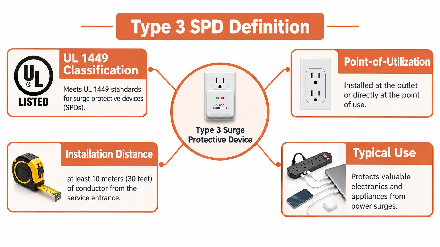
Under that classification, a Type 1 SPD may be installed between the service transformer secondary and either the line or the load side of the service-equipment overcurrent device. It is intended to operate without an external overcurrent protective device. A Type 2 SPD is installed on the load side of that service overcurrent device, including branch panels. A Type 3 device is a point-of-use product, cord-connected, plug-in, or receptacle, and the conductor length from the service panel to the utilization point must be at least 10 meters (30 feet), per UL's SPD classification summary.
A sketch before the ratings
Think of the building in three stops, and assign the mark before you open a datasheet.
Service entrance. This is the only stop where a line-side landing is even in play. The device has to carry a Type 1 evaluation if the design puts it on the line side of the service overcurrent device, or if the spec calls for a device intended to run without an external overcurrent protective device.
Distribution and branch panels. These land on the load side of the service overcurrent device. A Type 2 mark fits that location, including panels that feed industrial equipment.
Utilization equipment. A Type 3 plug-in, cord, or receptacle device belongs here, and only when at least 10 m (30 ft) of conductor separates that point from the service panel.
What procurement has to reject
A branch-panel device doesn't become a service device because the enclosure looks similar or the surge-current claim is larger. A line-side or other Type 1 location needs the Type 1 evaluation on the marking. A point-of-use strip doesn't replace the service or distribution device, even when the conductor-length rule is met.
The mark tells you the legal landing. It doesn't tell you the device is adequate for the exposure.
Contractors can use that sketch on a walkthrough. Service gear gets the Type 1 question first. Distribution panels get a Type 2 question. The receptacle or cord device is a supplement at the load, and only past the 10 m conductor boundary. Sensitive industrial equipment still needs the service and distribution layers. The point-of-use unit is not the scheme.
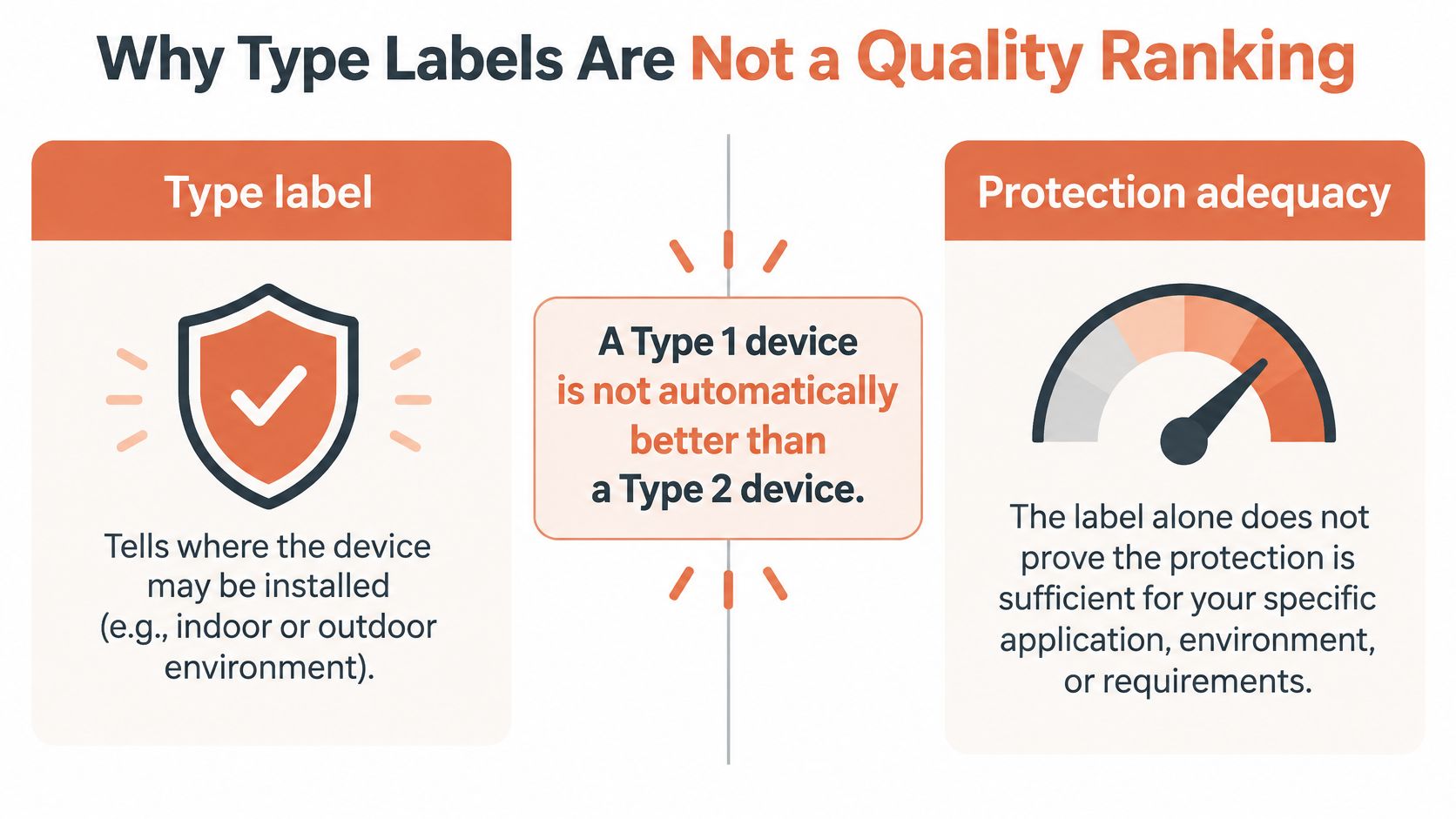
Why Type Labels Are Not a Quality Ranking
A higher type number is not better protection. Treat the common upgrade path, Type 3 to Type 2 to Type 1, as a location map someone misread as a performance ladder.
A Type 1 device isn't automatically better than a Type 2 device. A Type 3 plug-in unit isn't a stand-in for coordinated protection at the service and at distribution. UL 1449's type structure describes where the device may be installed. Adequacy is a separate question, and the label alone doesn't answer it.
Location marks versus test class
The IEC duty split is about the transient, not a grade.
Type 1 duty, IEC framing: These devices are for locations where a portion of lightning current may enter the installation. You can't assume a Type 2 device replaces that duty where higher-energy lightning current is expected.
Type 2 duty: These devices protect downstream distribution against induced lightning effects and switching transients.
Type 3 duty: These devices give localized, equipment-level protection. They don't absorb the service event by themselves.
IEC Class I uses a 10/350 μs waveform associated with direct-lightning exposure. Class II uses an 8/20 μs waveform for switching surges or indirect lightning. Those shapes aren't interchangeable labels. A device proven on the shorter switching waveform hasn't been shown, by that test alone, to carry partial lightning current at the service.
What to ask for on the submittal
Ask for two things, and don't let either one stand in for the other.
Ask
What it settles
What it doesn't settle
Marked UL type
Permitted installation location
Whether let-through and fault rating fit the load
IEC test class and waveform
Direct-lightning (10/350 μs) versus induced or switching (8/20 μs) duty
Which side of the service overcurrent device is legal
A facility with an external lightning protection system, or a service where part of the lightning current can enter, needs the higher-energy duty called out. A plant whose main threat is contactor and drive switching still needs distribution devices tested for that induced and switching waveform. Buying "Type 1 everywhere" wastes locations where a Type 2 device is the correct landing and still leaves residual voltage at the load if nothing is staged downstream.
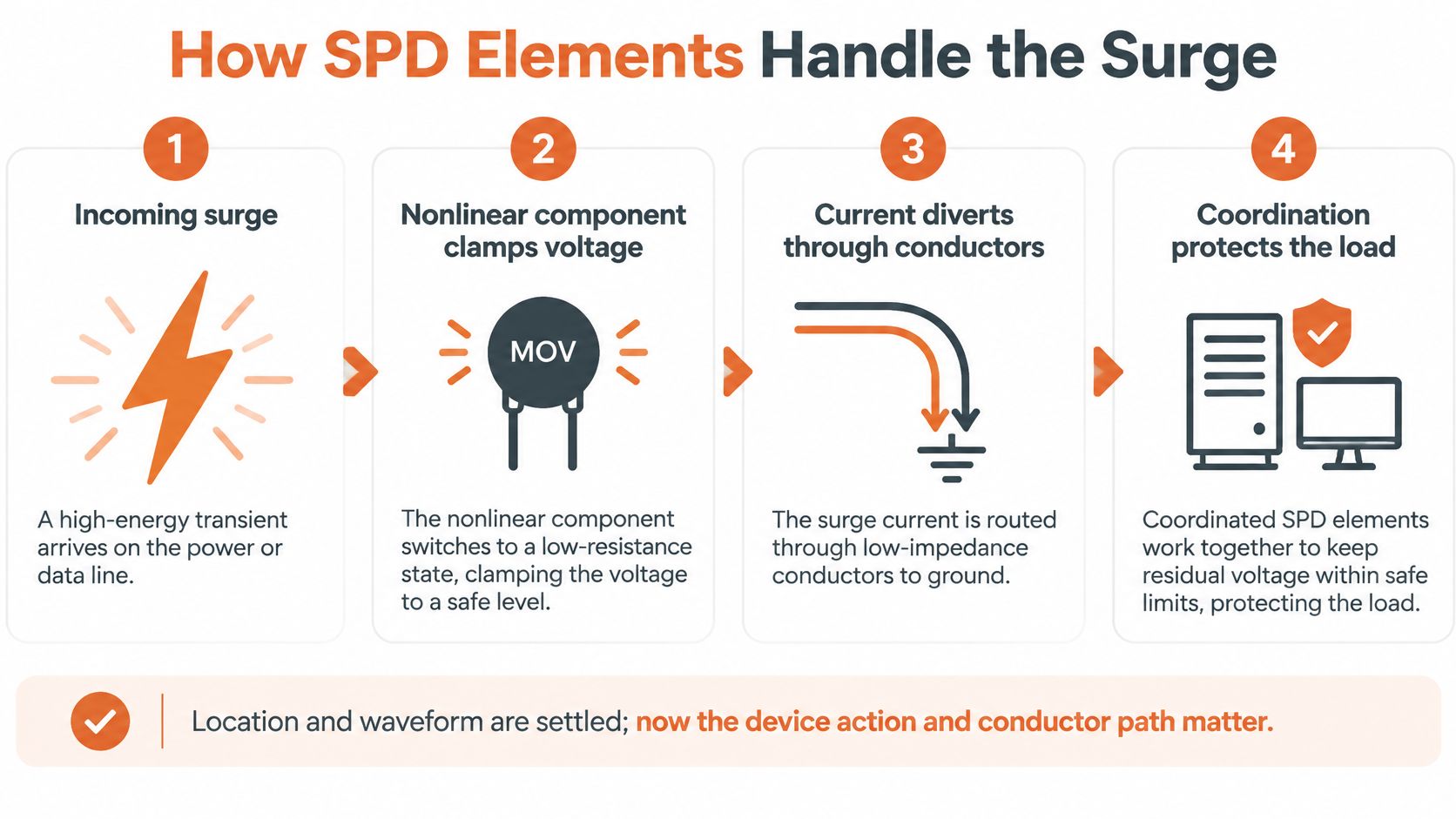
How SPD Elements Handle the Surge
An SPD contains at least one nonlinear component whose job is to limit surge voltage and divert surge current. IEC 61643 is the reference for that definition and, in IEC 61643-12, for selection, location, operation, and coordination on 50/60 Hz AC systems up to 1,000 V RMS. Naming that role isn't a substitute for the applicable code, the listing, or the manufacturer's instructions.
Three element behaviors
Voltage-limiting parts, metal-oxide varistors or avalanche components, reduce impedance continuously as voltage rises. They clamp fast transients. They also leak, run warm, and age. A limiting element that looks "always ready" is also a thermal and end-of-life problem the panel has to live with.
Voltage-switching parts, such as gas-discharge devices, stay comparatively high impedance until a breakdown threshold, then conduct heavily. Surge-current capability can be high. Let-through can also be higher, and follow current has to be considered, because the device may keep conducting after the surge until the system voltage and the circuit allow it to extinguish.
Hybrid assemblies combine the two. The switching element takes energy. The limiting element holds residual voltage down. That balance is the point. A high surge-current element can still hand the load too much voltage if nothing clamps the front of the wave.
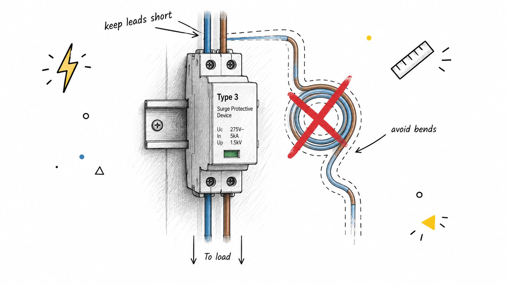
Leads are part of the scheme
Coordination is the layer outside the case. Upstream and downstream devices have to be chosen together, and the connecting conductors have to be short and straight. Lead length adds voltage while surge current is flowing. A tidy loop of extra wire can erase the clamp the cut sheet advertised.
The check that matters at the load is simple. The downstream device's voltage protection level has to remain below the equipment withstand level. If the upstream hybrid handles energy but the downstream leads are long, the control power supply still sees a high residual. Installers should treat conductor geometry as protection design, not as a neatness item on the punch list. IEC 61643-12 is the coordination reference for those AC systems. It doesn't replace the project engineer's withstand review.
Specs That Separate One SPD from Another
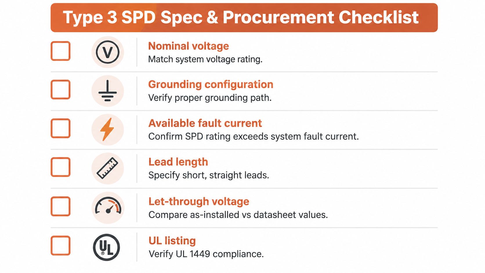
Behavior inside the case doesn't replace the side-by-side rating check. Nominal system voltage and a surge-current headline aren't enough to accept a substitute. UL certification records identify maximum continuous operating voltage (MCOV), voltage protection rating (VPR), nominal discharge current (In), short-circuit current rating (SCCR), phase configuration, and protection mode.
One documented UL-listed Type 2 device for a 120 V single-phase system shows how those numbers read in job language. The record lists a 150 V MCOV, 400 V VPR line-to-neutral and line-to-ground, 500 V VPR neutral-to-ground, 3 kA nominal discharge current, and 5 kA SCCR, according to the UL certification record for that Type 2 SPD. Those figures are an example of what a listing contains. They aren't a target to copy onto a 480 V board.
Ratings to compare on an SPD cut sheet
Parameter
Example from the listing
What to verify
MCOV
150 V
Sits above the continuous voltage the grounding arrangement actually applies
VPR, L-N and L-G
400 V
Let-through versus equipment withstand, mode by mode
VPR, N-G
500 V
Neutral-to-ground mode isn't the same number as the line modes
In
3 kA
Discharge current used in the nominal test, not the largest marketing surge claim
SCCR
5 kA
Compatible with available fault current, plus any required backup overcurrent protection
Marked type and phases
Type 2, 120 V single-phase
Location permission and system configuration match the one-line
MCOV is a withstand-the-system number. Set it from the actual continuous voltage, including how the system is grounded, not from the nominal nameplate alone. VPR is the let-through figure. Compare it mode by mode. A device that looks fine line-to-neutral can still be the wrong clamp neutral-to-ground.
In is the nominal discharge current in the listing. It isn't the catalog surge-ampere banner. SCCR has to live with the available fault current at that panel. If the listing requires backup overcurrent protection, that device has to be on the bill too. A deeper pass on how surge protection ratings are read keeps two candidates from being compared on mixed modes.
If MCOV, VPR, In, SCCR, or the marked type doesn't fit the system, a larger surge-ampere number doesn't save the substitution.
Protection Layouts for Real Facilities
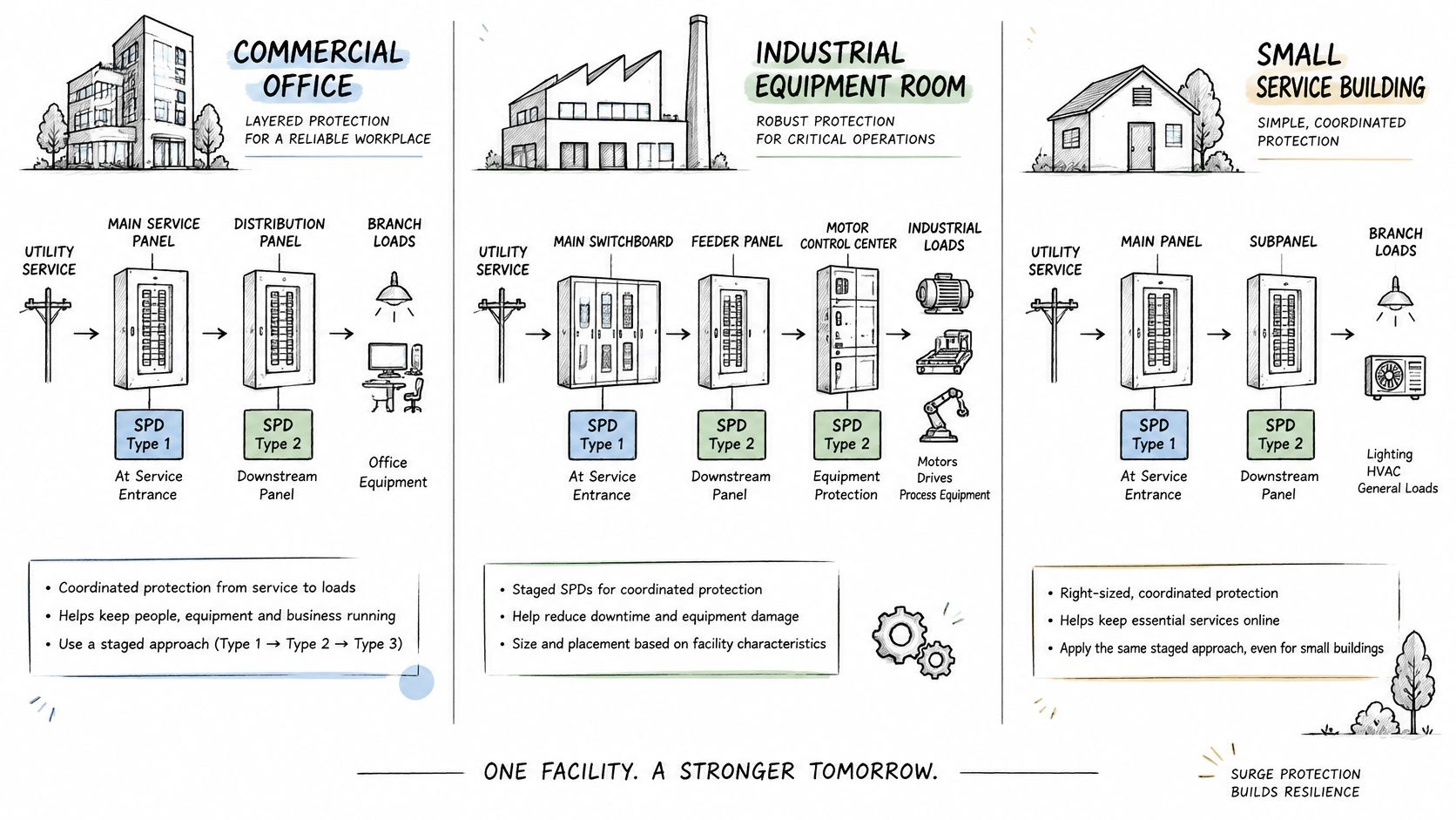
Individual ratings become a scheme only when each device has an exposure, a panel, and a load. The diagram below is the pattern. Service duty first, distribution next, equipment last. One part number doesn't cover the building.
Three AC layouts
Commercial or institutional service. Where the design expects service-entrance duty, specify a Type 1 device, or a device marked for both Type 1 and Type 2, at the service. Put Type 2 devices at distribution or branch panels so induced and switching energy doesn't travel the full feeder into lighting and HVAC controls. The service unit takes the higher-energy event. The panel units cut what remains.
Industrial control lineup. Keep the panel SPD on the load side of the service overcurrent device. Add localized protection only where conductor distance and a sensitive load justify a Type 3 device, such as a PLC rack or a drive that has already shown surge damage. A 100 A class distribution point is a common place this decision shows up. The panel device and the feeder arrangement on a 100-amp 3-phase panel still have to match the marked type before anyone adds a receptacle SPD.
Data room or healthcare branch. Treat the plug-in or receptacle device as the last reduction of residual voltage at servers, nurse-call gear, or imaging controls. It isn't the only SPD on the building. Upstream service and distribution devices still have to be there. The point-of-use unit cleans up what those stages let through.
The short video below walks the same staging idea from service to equipment. Use it as a briefing clip, then put the marks on your own one-line.
Telecommunications and signaling: IEC 61643-21:2025 covers SPDs on those networks up to 1,000 V RMS and 1,500 V DC, including lines that also carry power, such as Power over Ethernet. Clamping or switching elements here aren't an AC panelboard SPD with a different label.
Photovoltaic DC: IEC 61643-31:2018 covers SPDs on the DC side of PV systems up to 1,500 V DC, including PV generator and inverter DC. It addresses permanently connected devices that need a tool for removal, and it excludes portable SPDs.
Other DC power: IEC 61643-41:2025 covers SPDs for DC low-voltage power circuits up to 1,500 V DC.
Stop the substitution when the circuit family changes. PoE, PV generator DC, and a DC power circuit each need their own device standard. An AC Type mark on the panel schedule doesn't cover them.
Selecting SPDs During BOM Review
Drawing the one-line and buying the alternate are different jobs. On alternate-product review, compare the complete certification marking. A similar voltage, a similar enclosure, or a similar surge-current claim isn't a match.
Under UL 1449, an SPD investigated for Type 1 applications is suitable for Type 2 applications and may be marked for both. An SPD marked only Type 2 isn't suitable for a Type 1 installation. That checkpoint is documented in the UL record on Type 1 and Type 2 marking. A line-side or other Type 1 location can't be filled with a Type 2-only device.
The pass that rejects a bad alternate
Run the markings in one pass, and stop at the first miss.
Application category: Type 1 where the spec requires Type 1. A dual mark is acceptable for a Type 2 landing. A Type 2-only mark isn't acceptable for a Type 1 landing.
Electrical fit: Nominal system voltage, MCOV, VPR by mode, nominal discharge current, SCCR, and phase configuration have to agree with the system.
Protection hardware: Any required backup overcurrent device is on the bill, not assumed.
Documentation: The manufacturer's certification marking and application category are in the submittal, not reconstructed from a catalog photo.
ATEK Distribution can review that bill of materials, chase a hard-to-source protective device, coordinate with the manufacturer, and check an approved alternate when lead time threatens a service, distribution, or controls package. Send the one-line location, system voltage, available fault current, and the marked type the spec requires. Ask for availability and documentation, and accept a like-for-like alternate only when the markings match the location. Applicable codes, the manufacturer instructions, and the project engineer still govern the installation.
ATEK Distribution helps engineers, contractors, and procurement teams source surge protective devices and the distribution gear around them, including hard-to-find alternates and the certification markings a submittal needs. If a service, panel, or controls package is waiting on the right SPD, send the location and the required type. Visit ATEK Distribution to start a BOM review or a quote.
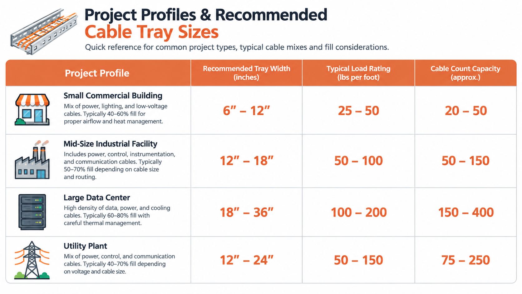
A contractor is reviewing a tray submittal for an industrial feeder run. The plan calls for a wide tray, but the cable schedule is still changing, the support spacing hasn't been confirmed, and nobody has shown that the selected tray meets the project's load requirement. The width looks plausible. The selection isn't complete.
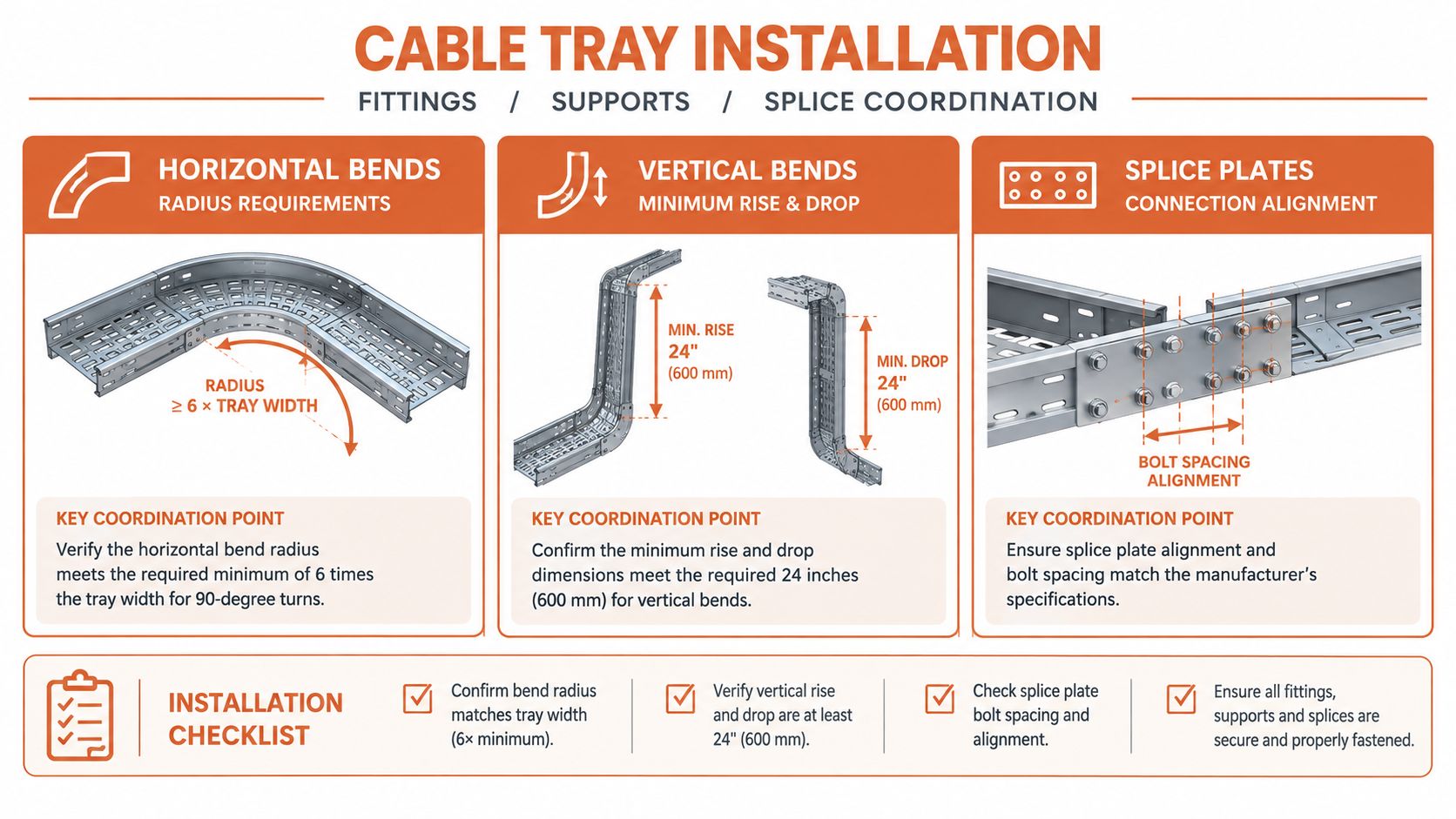
Cable tray sizes are a coupled engineering and procurement decision. Inside width, usable depth, cable arrangement, support span, thermal performance, fittings, and structural rating all affect whether the proposed system works. A tray that passes a fill check can still fail the load check, and a tray with adequate structural capacity can still leave cables crowded or running too hot.
The tray submittal is often the first place where the design's separate assumptions meet. Engineering has the cable list, the electrical contractor has the route and support layout, and procurement needs a product description complete enough to source and quote. Each group affects the result.
Consider a project specifying a 24-inch tray on a 20-foot support span. Those dimensions alone don't establish suitability. The design still needs to confirm usable width and depth, cable fill and arrangement, cable weight, the tray's tested capacity at that span, fitting locations, and any required concentrated load. NEMA's load designation can help describe the tray's performance, but it isn't a substitute for the manufacturer's data for the selected construction and configuration (NEMA VE 1 scope and contents).
A reliable review separates the checks, then brings them back together:
Define the route and cable population. Track what travels through each segment, including branches and planned additions.
Check physical arrangement. Use cable outside diameters and the applicable fill or single-layer rule.
Check heat and separation. Confirm the arrangement meets the project's ampacity, spacing, and segregation requirements.
Check structural performance. Compare cable and tray weight, span, and other specified loads with manufacturer-tested data.
Coordinate the complete system. Include fittings, supports, splices, covers, and hardware in the specification.
Practical rule: If the quote identifies only nominal width, the distributor may be pricing a product that doesn't match the engineered requirement.
The width is a visible selection. The design basis behind it is what makes it a usable one.
Cable Tray Constructions and How They Change Sizing
Tray construction affects ventilation, cable support, and how the electrical fill calculation applies. Decide which construction the project needs before comparing dimensions.
Ladder tray supports cables on rungs and leaves open space between them. That arrangement is commonly considered for power distribution routes where access, cable exits, and airflow matter. The opening pattern and rung layout still need to suit the cable types and installation.
Ventilated trough has a more continuous base with openings for ventilation and drainage. It can provide closer cable support than a ladder configuration, so confirm that the cable sizes and installation method suit the selected tray.
Solid-bottom tray provides a continuous base. It may be selected where the design calls for that construction, but it has different fill and thermal considerations from open tray. A covered solid-bottom system shouldn't be treated as interchangeable with an open ladder run just because both have the same nominal width.
Materials and finishes also belong in the decision. Industrial projects may specify metal tray with a suitable finish or a nonmetallic system, depending on the environment and project requirements. The required material, finish, fittings, and documentation should follow the specification and manufacturer's product data, not assumptions based on tray appearance.
The selected construction determines which fill limits and thermal checks are relevant. That's why the same cable list may lead to different tray arrangements when the project changes from ladder to ventilated or solid-bottom tray. Check the actual cable types, route conditions, and applicable requirements before choosing a family.
Standard Cable Tray Widths and Inside-Width Progression
For sizing, the dimension that matters is the usable inside width, not just the outside or nominal product dimension. A technical overview referencing the NEMA and CSA framework lists standard inside widths of 6, 9, 12, 18, 24, 30, and 36 inches, equivalent to approximately 152, 229, 305, 457, 610, 762, and 914 millimeters (ABB Electrification Canada cable tray technical overview).
Inside Width (in)
Inside Width (mm)
Typical Use
6
152
Narrow routes, subject to cable arrangement and capacity checks
9
229
Compact routes where the cable schedule fits
12
305
Smaller distribution and control routes, if verified
18
457
Intermediate-width routes
24
610
Wider routes requiring a project-specific fill and load check
30
762
Large cable populations, subject to structural verification
36
914
Wide routes where the layout and load data support the selection
The progression increases in 3-inch increments through 12 inches, then in 6-inch increments up to 36 inches. The same overview limits outside width to no more than 2 inches (50.8 millimeters) greater than inside width, allowing for side rails and construction. That allowance is useful for interpreting drawings, but it doesn't make outside width a substitute for usable cable space.
Choose inside width against the cable outside diameters, any required separation, future circuits specified by the project, and the physical layout at fittings. A tray that appears adequate on a plan can still fail when large cables must fit side by side or bend through the selected fitting geometry.
Usable Loading Depth and Cable Outside Diameter
Width controls the side-by-side arrangement. Usable loading depth determines how much cable can be accommodated vertically and whether the intended layer arrangement is practical. Typical U.S. specifications commonly use loading depths from 3 to 6 inches, but the usable dimension and permitted cable arrangement need to be verified against the selected product and project requirements (Los Alamos National Laboratory cable tray specification).
For 4/0 AWG and larger multiconductor cables, NEC Article 392 sizing practice requires a single layer, with the tray's inside width at least equal to the sum of the cable outside diameters. At that threshold, cable diameter and width arrangement govern the fit check. A cross-sectional-area calculation alone won't show whether the cables can lie in the required layer.
Depth still matters on a heavy feeder route. A deeper tray may accommodate the required cable height or give the installation more practical room, but it doesn't override a width constraint, thermal limit, or load rating. Nor does extra depth automatically create useful future capacity if the added cables would require a different arrangement.
Check fitting geometry at the same time. Cable minimum bending radii can govern the fitting radius and may make a tight turn impractical even when the straight tray has ample width and depth. The final selection should reflect the usable tray envelope and the cable manufacturer's requirements, not just the dimensions shown in a plan view.
NEC Fill Rules by Tray Type and Cable Class
A fill percentage isn't a universal answer. Under the U.S. NEC Article 392 framework, the applicable check depends on cable class and tray construction. Confirm the governing code edition, project specification, and product documentation for the installation.
Cable Class
Ladder or Ventilated
Solid-Bottom
Control and instrumentation cables
Commonly 50% fill limit
Commonly 40% fill limit
Smaller multiconductor power cables
Applicable allowable-fill area for the tray type and width
Applicable allowable-fill area for the tray type and width
4/0 AWG and larger multiconductor cables
Single layer, with inside width at least the sum of cable outside diameters
Single layer, with inside width at least the sum of cable outside diameters
For smaller multiconductor cables, compare their aggregate cable cross-sectional area with the applicable allowable-fill area for the tray type and width. For large multiconductor cables, use the single-layer width check instead. Don't apply the control and instrumentation limits as though they were blanket limits for every power-cable arrangement.
Mixed routes need each relevant rule checked, not just one total area. For example, the control-cable group must meet its applicable fill limit, the smaller power cables must meet their allowable-fill-area requirement, and any large multiconductor cables must fit the required single layer. If the project specifies spare capacity, include the planned future cables in the relevant checks rather than treating spare space as an informal percentage.
For the cable schedule, use actual product data for cable outside diameters. A cable family or conductor size alone may not establish the installed outside dimension. A distributor can help review the wire and cable portion of a bill of materials, including tray cable and wire sourcing, while the engineer confirms the applicable electrical and structural requirements.
NEMA Load Classes, Spans, and What the Designation Means
A NEMA VE 1 designation packs two decisions into one shorthand: support span and working-load category. The commonly used working-load categories are 50 lb/ft for Class A, 75 lb/ft for Class B, and 100 lb/ft for Class C. A designation such as 20C identifies a 20-foot support span paired with the Class C working-load category (NEMA VE 1 scope and contents).
That shorthand helps engineers and distributors communicate, but it is not a universal allowable load for every tray. Capacity depends on construction, material, rung and side-rail design, splice location, support configuration, environment, and the manufacturer's tested load tables. Project specifications often add requirements on top of the distributed cable weight. One published government specification requires a 200-pound concentrated load at mid-span, alongside the specified uniformly distributed load, with a safety factor of 1.5 for the stated test arrangement (published government cable tray specification).
The class letter says nothing about width or depth on its own. Treat the designation as one variable in the coupled sizing decision: width, depth, span, and class move together, and a label covering only span and load category cannot settle the other two. On the quoting side, the class designation is what gets priced first, but the manufacturer's load table is what gets verified.
How to use the designation in a comparison
A 12-inch 20A and a 24-inch 20C are not interchangeable just because both carry a 20-foot span designation. The first indicates a lower working-load class, and the wider tray brings different geometry and potentially different tested capacity. Neither label, by itself, confirms whether the product passes the project's cable-weight and load requirements.
Request the load table matching the specified width, depth, material, and construction at the project's support span. Include cable weight, tray weight, covers, and other supported equipment where applicable. A tray that passes the fill check can still be structurally unsuitable if the combined load exceeds its verified capacity.
IEC 61537 Load, Deflection, and the International Translation
Cross-border projects need more than a conversion between metric and imperial dimensions. IEC 61537 sets requirements and tests for cable-tray and cable-ladder systems, including mechanical performance under specified loading conditions. Its framework covers safe working load, fittings, cantilevers, pendants, load distribution, and deformation.
The cited mechanical limits include lateral bending of support lengths and fittings up to 1/100 of the support spacing, and transverse bending up to 1/20 of nominal width under the nominal safe working load. The standard also includes a collapse check at 1.7 times the rated load. These limits describe tested performance conditions, not a standalone tray selection method. The current international edition identified by the IEC webstore is IEC 61537:2023 (IEC 61537 load-value overview and standard context).
A tray specified at 600 mm width with supports 3 m apart must be checked against the manufacturer's tested load table for that geometry, material, depth, and fitting configuration. Converting a NEMA class label into metric units won't establish equivalence if the test conditions and reporting basis differ.
For a submittal comparison, line up the actual test basis: span, rated load, deflection criteria, configuration, and the product data supporting the declared capacity. Width and depth are part of the specification, but the load and deflection results are what show whether the selected system suits the route.
Thermal Ampacity and the Hidden Limit on Tray Width
Passing the physical-fill calculation doesn't guarantee that the cables can carry their intended current in the proposed arrangement. Thermal ampacity depends on cable type, tray construction, spacing, layering, and cover conditions. A covered tray can change the thermal assessment, and stacking cables or reducing spacing can alter it even when the fill calculation passes.
That's why the familiar 40% to 50% planning rule isn't a universal sizing result. It can be a useful prompt to review space, but it doesn't replace the applicable fill calculation or ampacity determination. A route may meet its fill limit and still require conductor derating; a thermally acceptable arrangement may still violate the applicable physical-fill rule. Keep those checks separate.
A wider tray isn't automatically the remedy for a thermal problem. The cable arrangement and ventilation may matter more than the nominal width.
Depending on the engineering review, the practical fix could be more spacing, a different tray construction, a revised route, or separate parallel runs. Adding width along the same route may not improve heat dissipation enough, particularly if covers or close cable grouping remain unchanged.
For heavy feeders, use manufacturer-certified cable data and evaluate the complete installation before selecting tray dimensions. A sourcing review for a specified conductor, such as 500 kcmil aluminum cable, can help confirm the product data needed for the calculation. The engineer remains responsible for verifying the applicable code and installation conditions.
Worked Sizing Scenario From Cable List to Selected Tray
A useful sizing review starts with the cable list, not a preferred tray width. Consider a representative 480 V industrial feeder sharing a route with control and instrumentation cables. The project team has identified a large multiconductor feeder group that includes 4/0 AWG and larger cables, plus smaller power and control cables. The cable schedule is still subject to confirmation, so the tray selection remains provisional.
Build the route-specific cable schedule
For each cable type, obtain the installed outside diameter and weight from the manufacturer. Record quantity, service, route segment, required segregation, and any documented future circuits. Split the route at branches and fittings, because the cable population and loading can change downstream.
The first attempt is a width-only selection based on the overall cable list. It fails as a complete design: it doesn't show whether the large multiconductor cables fit in a single layer, whether the smaller cable groups meet their separate fill limits, or whether the combined cable and tray weight is acceptable at the specified span.
Apply the checks in order
First, compare the sum of the outside diameters of the 4/0 AWG-and-larger multiconductor cables with the usable inside width. That single-layer check can determine the minimum width before the control-cable fill calculation is considered. Next, calculate the applicable fill for the smaller power and control groups under the tray construction and project requirements.
Then test the cable arrangement thermally, including any cover or spacing conditions. Add only project-defined future cables to the schedule, and assess their effect on both fill and weight. Don't use an undocumented spare allowance as a substitute for identified future demand.
Finally, compare cable load plus the tray and other supported loads with the manufacturer's tested data for the selected width, depth, material, support span, and fittings. If the candidate fails any check, revise the width, depth, support arrangement, or route, then repeat the affected checks. The result is a documented selection, not a guess based on cable count.
Quick Reference Table for Common Project Profiles
A profile table can narrow the product search, but it can't replace the cable schedule or manufacturer load data. The entries below identify standard width options and the information still needed to establish a final selection. The specified span and NEMA class must come from the project's structural requirement and verified product data, not the facility label.
Project Profile
Width x Depth
Span (ft)
NEMA Class
Small commercial feeder
Select from standard inside widths after cable and fill review
Project-defined
Verify from load table
Heavy industrial distribution run
Select from cable arrangement and load calculation
Project-defined
Verify from load table
Data center bus route
Select after construction, segregation, and thermal review
Project-defined
Verify from load table
Utility switchyard control run
Select from cable schedule and applicable control-cable fill
Project-defined
Verify from load table
Use the table as a shortlist, then verify fill, cable arrangement, ampacity, weight, and span for the actual route. This overview may help orient a project team before it reviews its own submittal:
Fittings, Supports, and Splice Coordination
The straight tray selection doesn't settle the route. Horizontal and vertical fittings must accommodate the cable's minimum bending radius, and branch fittings must suit the cable paths leaving the main run. Check the fitting radius against the cable manufacturer's requirement rather than assuming the tray width defines an acceptable turn.
NEMA VE 2 recognizes support placement one-quarter span from a splice, mid-span from a splice, or directly beneath the splice. The one-quarter-span arrangement is identified as preferred because it minimizes splice stress and deflection. Tray lengths should be at least as long as the selected support span, and the schedule should show support spacing and splice locations (Eaton cable tray design considerations).
Coordinate the tray length, support type, splice hardware, fittings, and cover specification in the same package. Supports have to carry the complete cable-tray wiring system, not just the installed cable quantity (NEMA VE 2 installation guidance).
For an adjacent cable-support application that uses a different system, such as a Caddy J-hook, verify the specified product and installation requirements rather than treating it as a replacement for a designed tray run. Mixing support types without coordinating the route can complicate installation and documentation.
Procurement Checklist and Submittal Fields That Get a Clean Quote
A complete request for quotation should identify the engineered selection, not just the nominal width. Include:
Dimensions: Usable inside width and usable depth.
Construction: Tray type, material, and finish.
Structure: Support span, NEMA or IEC load class, and verified load data.
System components: Fittings, splice hardware, covers, and compatible supports.
Project documentation: Required product submittals and applicable Buy American Act, Trade Agreements Act, or supplier-diversity documentation where required.
If you're coordinating contractor pricing with the electrical scope, Black Rhino Electric's electrical quote request is a separate resource for that conversation. For tray procurement, provide the route drawing, cable schedule, specifications, and approved alternatives so the quoted product can be checked against the design basis.
ATEK Distribution can assist with BOM review, hard-to-source tray families, manufacturer coordination, approved alternatives, and compliance documentation. Send the complete tray package rather than a width-only request to help keep quoting and project review aligned.
Contact ATEK Distribution for cable tray sourcing, project-specific BOM review, or help evaluating approved alternatives when availability or lead times change. Visit ATEK Distribution to discuss the requirements and documentation for your project.
You're reviewing a submittal package for a control panel, and line one calls for a receptacle device described as Surge Protection Device Type 3. The catalog cut looks plausible. The voltage matches. Then you notice the panel feeding it is in the same room, there's no upstream SPD on the drawing, and nobody has confirmed the grounding arrangement. That small line item just became an engineering question, not a purchasing task.
Where a Type 3 Surge Protective Device Fits in a Real Project
Most Type 3 problems start at the review desk, not in the field. A contractor submits a plug-in or receptacle unit because the specification says point-of-use protection. The datasheet shows a voltage rating and a surge rating, so the package moves forward. Nobody has checked whether the location, upstream protection, or conductor routing matches what a Type 3 classification assumes.
That's the core issue. A surge protection device Type 3 is the final coordination layer in a layered scheme, not a standalone fix for a sensitive load. It belongs close to computers, controls, medical electronics, communications equipment, and similar loads after service and distribution devices have handled larger transient energy.
Start With Position, Not the Catalog Photo
Before you compare brands, answer four project questions. First, is there properly rated Type 1 or Type 2 protection upstream. Second, does the actual branch-circuit routing support a point-of-utilization installation. Third, do the nominal voltage and grounding configuration match the device's marked ratings. Fourth, can the installer keep connections short and provide a low-impedance ground path.
If you can't answer those questions from the drawings, one-line diagram, and submittal, you don't have enough information to approve the device. Send it back for the missing details rather than treating a similar enclosure as proof of equivalence.
Practical rule: Approve the protection scheme first. Approve the individual Type 3 product second.
This distinction matters during substitutions too. A replacement may fit the same receptacle box or DIN rail space while carrying different voltage, short-circuit, or protection-level ratings. It may also assume a different branch protective device than the one already in the panel.
Facilities teams often bring these questions up after nuisance failures or damaged electronics, when the conversation expands beyond one SPD to broader power quality issues affecting sensitive equipment. That's late. The cheaper time to sort out coordination is before release, while panel space, conductor routing, and upstream device selection can still change without field rework.
What Defines a Type 3 Surge Protective Device
A Type 3 device is defined by where it sits in the electrical system. Under UL 1449 terminology, it's a point-of-utilization device installed at least 10 meters (30 feet) of conductor from the electrical service panel to the utilization point, measured along the conductor routing and excluding conductors supplied with or used to connect the SPD itself, as explained in NEMA's surge protection guidance on Type 3 installation distance.
Read that definition carefully during review. The measurement follows the actual conductor path, not a straight line across a floor plan. It also doesn't include the SPD's own connecting leads. A device a short walk from the panel could still meet the routing distance, while another device farther away on the drawing might not if the circuit path is direct.
Common Formats You Will See on Submittals
Cord-connected units: Familiar strips or assemblies connected between a receptacle and the load.
Direct plug-in devices: Compact modules inserted at the receptacle serving the equipment.
Receptacle SPDs: Devices built into the outlet itself for a cleaner installation at the point of use.
Protection integrated into utilization equipment: SPD components incorporated by the equipment manufacturer rather than added separately in the field.
None of those formats makes a product Type 3 by appearance alone. The listing, installation instructions, and location in the system decide whether the application is correct.
A Quick Position Check Against Type 1 and Type 2
Type 1 belongs at the service-entrance side of the scheme. Type 2 belongs at distribution equipment downstream of the service. Type 3 belongs at utilization equipment, after branch-circuit protection and with the required conductor distance behind it.
If a submittal calls the only SPD on a project Type 3, stop and ask what's upstream. If a receptacle device is mounted immediately beside the service panel, stop and ask whether the listed installation context has been met. The answer changes the specification. It may also change which product category the engineer should specify instead.
Key Performance Ratings to Verify Before Approval
A Type 3 datasheet can look complete while still hiding a mismatch with your system. Start with the relationship between maximum continuous operating voltage, called MCOV or Uc, voltage protection level (Up), and the protected load's withstand capability. That relationship tells you whether the device can live on the circuit during normal operation and still clamp a transient low enough to matter.
The scope matters too. IEC 61643-11 for low-voltage surge protective devices defines these devices as containing at least one nonlinear component to limit surge voltage and divert surge current, covering AC systems up to 1,000 V RMS at preferred 50/60 Hz frequencies. Within that framework, selection still depends on matching the ratings to the actual system, not on component technology alone.
Why MCOV Deserves the First Check
If MCOV is below the system's sustained line-to-ground voltage, the SPD can conduct during normal operation. That leads to overheating, premature degradation, or failure. Go too far the other way and the higher voltage rating generally increases residual let-through voltage, reducing protection for the load you bought it to protect.
Don't approve based on nominal system voltage alone. Confirm the grounding configuration and the voltage the device will see in its connected mode. Then compare Up or tested clamping data at the specified impulse against what the downstream electronics can tolerate. A low advertised number doesn't help if it's stated under conditions that don't match your application.
Type 3 SPD Ratings to Check on Every Submittal
Rating
What It Controls
Reviewer Red Flag
MCOV / Uc
Continuous voltage the device can withstand
Rating selected from nominal voltage without checking grounding
Up / let-through voltage
Residual voltage reaching the load during a surge
Value given without the test condition or impulse basis
Short-circuit rating
Ability to remain safe under available fault current
No confirmation against the panel's fault current
Backup overcurrent protection
Required breaker or fuse coordination
Manufacturer requires a device that isn't in the BOM
Thermal disconnection
Safe end-of-life behavior
No clear disconnection method stated
End-of-life indication
Ability to detect lost protection
No visible status or remote indication for maintenance
For a deeper check on how these values are presented and compared, review the basics of a surge protection rating and what each value means before you sign off. Metal-oxide varistors, gas-discharge components, or coordinated combinations can all appear in suitable products. The technology label is secondary. The tested ratings, listing, and system match determine whether the submittal should pass.
How Type 1, Type 2, and Type 3 Devices Coordinate
Treat layered surge protection as one system with three jobs. Type 1 equipment handles higher-energy events at the service entrance. Type 2 equipment reduces what remains at distribution panels. Type 3 equipment provides the final local clamping near sensitive loads.
The diagram below shows that division of labor as energy moves toward the equipment.
The Distance Is Part of the Coordination
Conductor distance between stages adds impedance. That impedance helps keep upstream and downstream devices from behaving as if they were connected at exactly the same electrical point. It's one reason a Type 3 unit placed very close to an upstream SPD deserves an engineering check instead of automatic approval.
Location relative to overcurrent protection matters just as much. A Type 3 SPD is installed downstream of service equipment and branch-circuit overcurrent protection, on the load side of the service-disconnect overcurrent device and branch-circuit protection, with at least 10 meters of conductor distance from the service disconnect, as described in UL 1449 material on permitted SPD installation locations. It's connected to an already protected circuit. It doesn't replace the breaker, the service protection, or the upstream SPD.
The short video below is useful when you're walking a junior installer through stage placement before rough-in decisions lock in the routing.
Two coordination errors show up repeatedly. The first is specifying Type 3 protection with no upstream Type 1 or Type 2 device, leaving the small point-of-use unit exposed to energy it wasn't intended to manage alone. The second is placing stages so close together that the assumed separation disappears. Both errors can make a correctly manufactured product perform like a poor specification.
Document the upstream arrangement on the submittal. Mark the panel-to-load routing, note the branch protective device, and confirm grounding and bonding conditions. If those facts aren't on paper, coordination is being assumed rather than verified.
Installation Details That Decide Real-World Performance
The datasheet gives you a tested protection level. The field installation determines how much additional voltage the load sees before that clamping helps. Lead length and routing are where good specifications lose performance.
UL 1449 installation instructions require conductors connecting the SPD to the line or bus and ground to be no longer than necessary and to avoid unnecessary bends, with guidance recommending leads as short and straight as reasonably possible, generally one meter or less, because surge voltage increases with the inductive effect of conductor length and bends during a fast transient, according to Intertek's summary of UL 1449 SPD installation requirements.
The rail-mounted example below is a useful reference for keeping the connection path compact inside a control enclosure.
Details to Inspect Before the Panel Closes
Lead routing: Remove coiled excess wire and avoidable bends. The complete connection path counts, not just the lead supplied with the device.
Ground path: Keep the route direct and low impedance. A long, indirect ground conductor undermines the protection level the spec relied on.
Device placement: Mount the SPD close to the protected circuit conductors where the listing and wiring diagram allow it.
Overcurrent compatibility: Confirm the branch breaker or fuse matches the manufacturer's instructions, including interrupting requirements where specified.
Conductor size and terminations: Follow the listed wiring instructions and verify field terminations are properly torqued.
A neatly coiled extra lead inside a panel may look tidy. During a fast transient, that coil is part of the voltage problem.
I've seen panels where the specified device was correct, the breaker was correct, and the installation still needed rework because the SPD was mounted where space remained rather than where the leads could stay short. Layout is an electrical decision here. Panel builders should reserve the SPD location during design, not after every other component has claimed the rail.
For receptacle and plug-in formats, the same principle becomes simpler but not automatic. Confirm the device serves the intended load, the branch circuit is the right one, and the installation context still matches the Type 3 listing. Don't let convenience decide placement.
A Spec and Procurement Checklist for Type 3 Devices
Engineering approval and purchasing approval aren't the same task. Engineering confirms the device fits the system. Procurement confirms the exact listed product, documents, and accessories will arrive without a silent substitution. A shared checklist keeps those decisions aligned.
Use the table below as a release gate. If a row can't be marked complete, the BOM isn't ready.
Review Area
Confirm Before Release
System voltage
Nominal voltage, connected mode, and sustained line-to-ground voltage match MCOV
Grounding configuration
System arrangement and bonding path verified against the wiring diagram
Available fault current
SPD short-circuit rating and backup protection are suitable for the location
Upstream SPD scheme
Type 1 or Type 2 device identified by location, listing, and rating
Panel-to-load distance
Actual conductor routing documented, excluding the SPD's own leads
Device ratings
MCOV, Up at the stated impulse, surge rating, and short-circuit rating recorded
End-of-life behavior
Thermal disconnection and status indication confirmed
Installation requirements
Lead routing, conductor size, breaker or fuse, and mounting location reviewed
Documentation
Listing information, installation instructions, wiring diagram, and compliance records attached
BOM cross-reference
Submitted model matches the purchase description with no unapproved alternate
Where Procurement Usually Gets Tripped Up
The risky moment is the alternate. A supplier offers a unit with the same nominal voltage and a similar form factor, but the Up, MCOV, or short-circuit rating differs. Another alternate needs a backup fuse that isn't included. A third looks identical but has no usable end-of-life indication for the maintenance team.
Send alternates back through the same table. Don't compare them by headline ratings in an email thread. For panel builders, also confirm rail space, receptacle configuration, conductor entry, and whether the replacement changes lead routing. Those details affect both compliance and as-installed performance.
Common Misconceptions That Lead to Misapplied Type 3 SPDs
The most persistent misconception is simple: if it plugs in and says surge protection, it must be Type 3. That isn't how the classification works. UL guidance on Type 3 SPD classification and utilization-point installation describes cord-connected, direct-plug-in, and receptacle units installed with at least 10 m (30 ft) of conductor between the service panel and the SPD, excluding conductors used to connect the SPD itself. The format is only part of the story. Position and coordination complete it.
Ratings Cannot Fix a Bad Application
A higher joule rating doesn't correct a missing upstream device. A lower Up value doesn't correct a location that defeats coordination. A premium device installed in the wrong place can deliver a worse result than a basic listed device installed inside a complete, coordinated scheme.
Marketing comparisons encourage the opposite thinking. Buyers rank products by one number, then assume the installation details will sort themselves out. They don't. The protected load experiences the device, the leads, the grounding path, and the upstream scheme as one system during a transient.
Field test: If removing the upstream SPD from the drawing wouldn't change your Type 3 selection, your review is incomplete.
Another common shortcut is measuring the distance rule as a straight line through walls or across a room. Use the conductor routing. Then exclude the SPD connection conductors from that measurement. Those two details can change the conclusion on compact industrial projects where panels and loads sit close together.
The substitution trap is quieter. Two products may share an enclosure style while differing in MCOV, Up, backup protection, or short-circuit rating. If purchasing swaps one for the other without engineering review, the project no longer has the protection scheme that was approved. Most misapplied Type 3 devices aren't defective products. They're reasonable products released into the wrong system context.
Reviewing Type 3 SPDs on Real Projects
Use a fixed sequence every time a surge protection device Type 3 appears on a drawing or BOM. Consistency catches the details that ad hoc reviews miss, especially when the device looks too small to justify much attention.
A Four-Step Review Sequence
Confirm the layered scheme: Identify the upstream Type 1 or Type 2 protection and the sensitive load the final stage is meant to protect.
Confirm installation context: Verify branch-circuit position and conductor distance along the actual routing.
Confirm device ratings: Match MCOV, Up, short-circuit rating, backup protection, thermal disconnection, and indication to the system.
Confirm field execution: Check mounting location, lead routing, grounding path, conductor size, and manufacturer instructions before energization.
That sequence also gives procurement a clean way to handle alternates. An approved alternative isn't just a part with matching voltage. It's a listed device that preserves every electrical and installation assumption in the original submittal. If one assumption changes, the reviewer should see it before the order is placed.
A distributor can do more than quote a line item. ATEK Distribution can support BOM review, manufacturer coordination, compliance documentation, and sourcing for hard-to-find protective devices when a specified model is unavailable or an alternate needs proper documentation. Guidance is most useful before release, while engineering, purchasing, and the panel builder can still agree on one coordinated device.
Don't wait for commissioning to discover that the SPD beside the panel, the missing upstream stage, or the substituted receptacle unit changed the design intent. Put the routing, ratings, and upstream device on the submittal record. Then the Type 3 device can do the narrow job it was built for: clamp residual voltage close to the equipment that needs it.
If your next project includes a Type 3 SPD with an unusual voltage, a hard-to-source listing, or an alternate that needs a documented ratings review, contact ATEK Distribution for BOM support, approved alternatives, compliance documentation, and project-specific sourcing assistance. Send your panel details and current BOM so the review can confirm the device, its upstream coordination, and its availability before procurement locks in the wrong part.