
You've got a machine that needs 240 V, a service that's delivering something closer to 208 V, and a plant manager who wants a number you can defend. That's the normal starting point for buck boost transformer sizing, and it's also where most sizing jobs go wrong. Picking the next catalog size above load kVA feels safe. It isn't, because the transformer has to work at the lowest voltage the plant sees, during motor starting, and across a supply that may not stay put. Work it as a voltage-envelope problem first and a kVA problem second, and the selection gets much easier to justify to an inspector, a specifier, or procurement.
Table of Contents
- What Buck Boost Sizing Really Solves
- How to Size a Buck Boost Transformer in Six Steps
- Tap Settings and Adjusted kVA Worked Examples
- Derating, Motor Starting and Voltage Envelope Checks
- When a Buck Boost Transformer Is the Wrong Fix
- Efficiency, Documents and Pre-Order Checks
What Buck Boost Sizing Really Solves
Say a 10 kVA control panel commissions cleanly at 230 V on a mild morning, then trips on hot afternoons when the supply sags to 208 V. Nothing inside the panel changed. The source did. A buck boost transformer corrects a voltage ratio, usually connected as an autotransformer, so its nameplate kVA represents the correction component rather than the full load-through capacity. That distinction drives every decision that follows.
Every sizing job needs the same inputs before you open a catalog.
- Measured source voltage: Record it at the point of connection, not from a drawing.
- Required load voltage: Take it from the equipment nameplate or manufacturer data, with its tolerance.
- Phase configuration: Confirm single-phase or three-phase and how the load is connected.
- Load current: Use full-load amps, and note whether the load runs continuously.
- Buck or boost percentage: Calculate the correction from measured to required voltage.
Three traps account for most bad selections. First, sizing to nameplate kVA without checking capacity at the reduced input voltage. Second, treating motor starting as a steady-state question. Third, assuming a transformer can fix voltage that changes with load, which is a different class of problem covered in a broader look at common power quality issues in industrial facilities.
You'll leave with a six-step procedure, an adjusted-kVA table, starting and derating checks, a comparison against other fixes, and a pre-order checklist you can put in front of an inspector or plant manager.
How to Size a Buck Boost Transformer in Six Steps
Start with measurements, not catalog tables. A catalog assumes you already know your source voltage, your load voltage, and your load current. On a live site, at least one of those is usually a guess until someone logs it.
Step 1 Log the Source Voltage
Measure at the point of connection across a full operating cycle. Capture minimum, nominal, and maximum readings, including peak production, shift changes, and the times of day when trips happen. One meter reading taken at 9 a.m. tells you almost nothing about a 3 p.m. sag.
Use a recording meter or a power quality logger if you have one. If you don't, take timed readings under light load and full load and write them down with the load condition next to each one. That log becomes the voltage envelope you'll size against.
Step 2 Pull the Required Load Voltage
Take the required voltage and its allowable tolerance from the equipment nameplate or the manufacturer's data sheet. Don't substitute a nominal system voltage. Equipment rated for one voltage class may tolerate a narrow band, and that band determines whether your corrected output is acceptable at both ends of the envelope.
Note the phase configuration and whether the load needs a neutral. Record those now, because they can rule out an autotransformer connection outright.
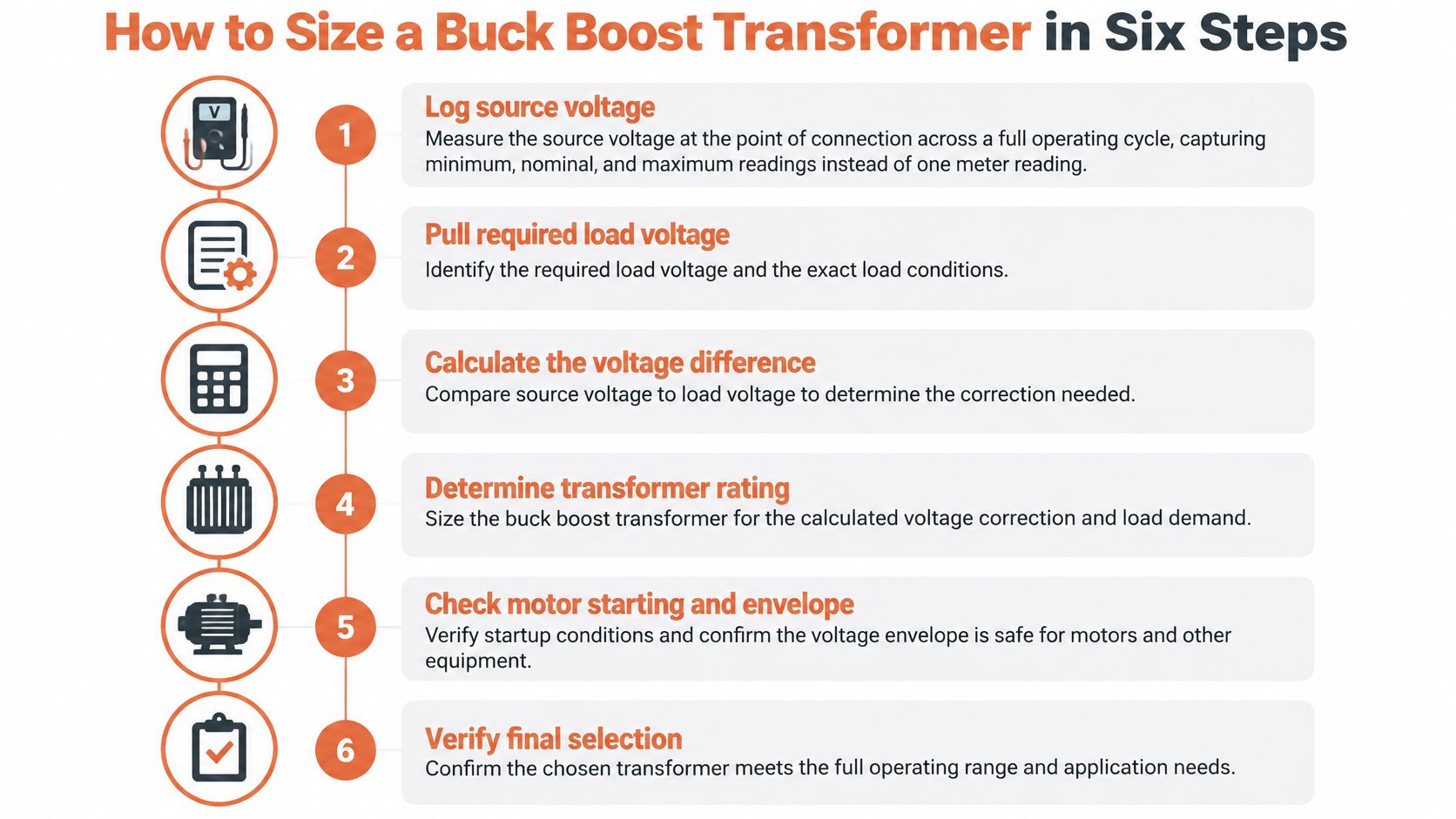
Step 3 Calculate the Correction
Buck or boost percentage = (target voltage - measured voltage) ÷ measured voltage × 100.
Say a 12 kVA load sits on a 208 V supply and needs 240 V. The correction is (240 - 208) ÷ 208 × 100, which is about 15.4% boost. Run that arithmetic at the minimum and maximum logged voltages too, not just at nominal.
Field rule: Size for the worst point in the envelope, then check that the opposite extreme doesn't push the load outside its allowable voltage range.
Step 4 Determine Load Current and Load kVA
Use nameplate full-load amps for load current. Then compute load kVA with the formula that matches your system.
- Single-phase: kVA = V × I ÷ 1000
- Three-phase: kVA = V × I × 1.732 ÷ 1000
Flag whether the load is continuous or intermittent. A load that runs for hours at full current stresses the unit thermally in a way a short-duty load doesn't, and that affects both selection and enclosure ventilation.
Step 5 Check Adjusted Capacity at the Lowest Input
This is the step people skip. The Eaton low-voltage dry-type buck-boost design guide documents the method as new kVA rating = actual output voltage ÷ rated input voltage × output kVA rating, with a 240 V input, 10 kVA output unit operated at an actual 220 V input giving an adjusted capacity of approximately 9.17 kVA.
Apply that formula at your lowest expected input voltage, not at nominal. Then select a rating that still covers load kVA at that low point with margin to spare. If it doesn't cover the load at the low point, the nameplate number is irrelevant.
Step 6 Verify the Installation Conditions
Before you finalize, check motor inrush, conductor ampacity, overcurrent protection, grounding, and neutral availability against the manufacturer's instructions for the specific unit. Confirm the applicable NEC articles with the project's engineer or inspector rather than relying on a general guide. Manufacturer instructions and the adopted code govern the connection, and neither a distributor nor a selection chart overrides them.
The most common error is simple. Someone picks the next nameplate size above load kVA at nominal voltage, and the unit ends up undersized at the low point the plant sees. Steps 1 and 5 exist to stop exactly that.
Tap Settings and Adjusted kVA Worked Examples
Nameplate kVA misleads because it's stated at rated input voltage. Run the unit below that voltage and usable capacity falls in proportion. The table below applies the design-method formula, adjusted kVA = actual input ÷ 240 V × 10 kVA, to a hypothetical 10 kVA unit rated 240 V input so you can see the reduction row by row.
Adjusted kVA for a 10 kVA buck boost unit rated 240 V input
| Actual input voltage (V) | Adjusted kVA | Reduction vs. nameplate |
|---|---|---|
| 240 | 10.00 | 0% |
| 230 | 9.58 | 4.2% |
| 220 | 9.17 | 8.3% |
| 208 | 8.67 | 13.3% |
| 200 | 8.33 | 16.7% |
Reading the Table Against a Real Load
Look at the 208 V row. The unit yields about 8.67 kVA there. If your load is 9 kVA, you're already over capacity at that input, even though the nameplate says 10 kVA and the selection looked comfortable on paper. That's not a marginal miss. That's the difference between a unit that runs within rating and one that runs hot every afternoon.
The 230 V row shows the same effect in smaller form. You're down to 9.58 kVA, so a load sitting just under nameplate has almost no margin left for continuous duty, enclosure heat, or a further dip.
At 200 V you've lost roughly a sixth of nameplate capacity. If your logged minimum is anywhere near that level, sizing from nominal voltage will undersize the unit by a wide margin.
A Second Worked Example With Margin
Say you select a 12 kVA-rated unit fed from 220 V against a 240 V rating. Adjusted capacity is 12 × 220 ÷ 240, which gives about 11.0 kVA. Against a hypothetical 10 kVA load, that leaves roughly 10% margin at the low point. Whether that margin is enough depends on duty cycle, ambient conditions, and starting demands, but at least you're evaluating margin at the voltage that matters.
Now run the same load against a unit chosen only because its nameplate exceeded 10 kVA. At 208 V you'd be working with a much thinner cushion, and any additional sag eats it entirely. I would rather defend a slightly larger unit with documented margin at minimum input than explain a thermal failure later.
Choosing the Tap
Most units offer discrete taps that connect the input to the correction you need. Choose the tap nearest your measured supply that produces the target output, and confirm the connection on the manufacturer's wiring diagram for that exact unit. Tap designations aren't interchangeable between manufacturers or even between product lines.
If your supply swings across two taps, size and set the tap for the worst-case output, then check the other extreme. A tap that delivers correct voltage at minimum input may overvoltage the load at maximum input. Both ends of the envelope have to land inside the equipment's allowable range. If no single tap does that, you don't have a tap problem. You have a voltage stability problem, and a different fix applies.
Set the tap for the worst case, then prove the opposite extreme is still acceptable. Checking only one end is how overvoltage damage gets designed in.
This table applies the formula only. It doesn't replace nameplate values, tap connections, or rated voltages from the manufacturer. Use it to screen candidate sizes, then verify the final selection against the submittal and wiring diagram before you order.
Derating, Motor Starting and Voltage Envelope Checks
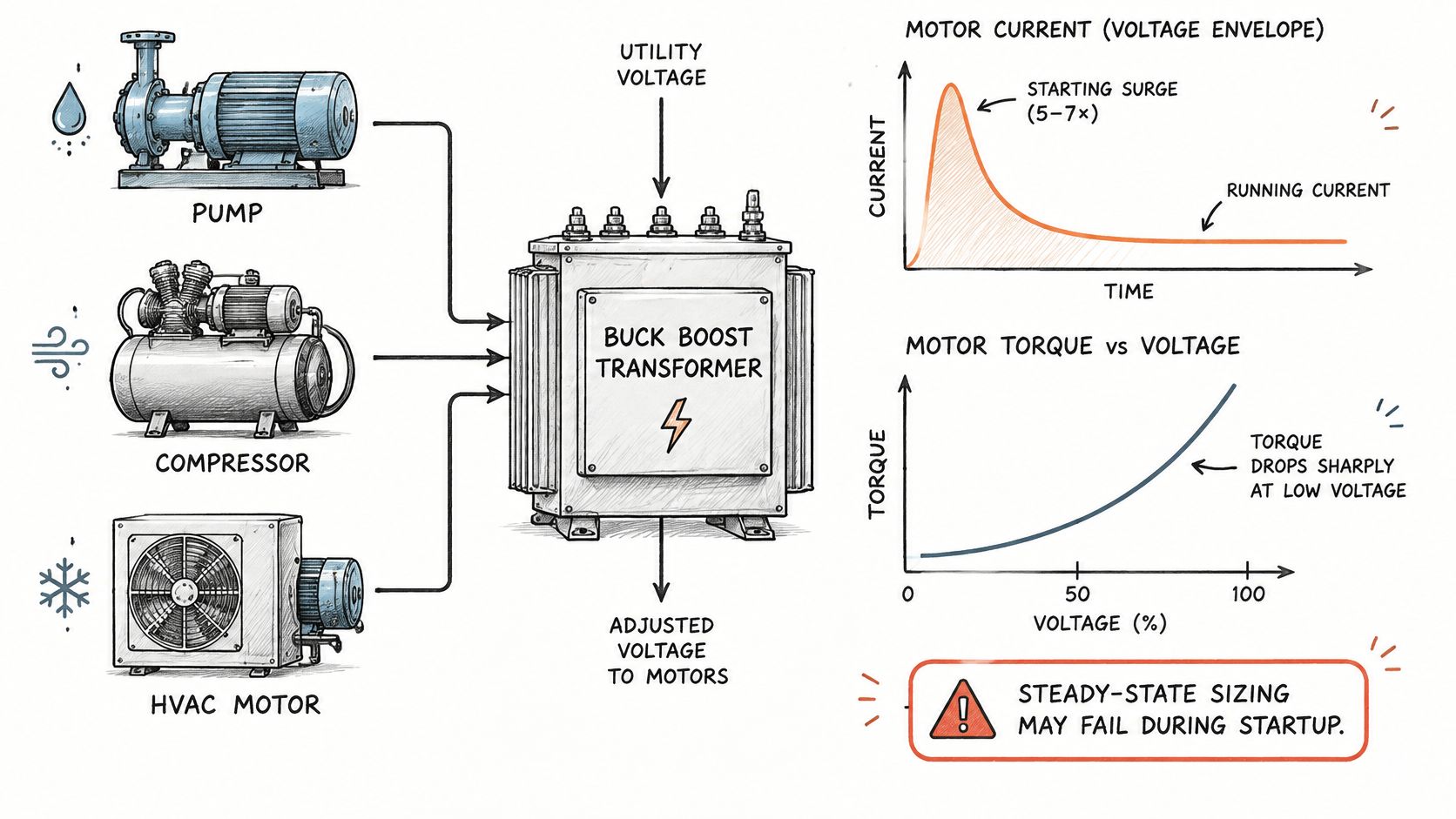
A motor that won't start doesn't care that your steady-state math was correct. Manufacturer guidance summarized in the Schneider Electric buck-boost FAQ notes that motor starting current can reach roughly five to seven times running current and that motor torque falls approximately with the square of voltage. Run the numbers on that second point. A 10% undervoltage at start leaves you with about 81% of rated torque, a loss of roughly 19%. For a loaded compressor or a pump starting against head pressure, that's often the difference between accelerating and sitting at locked rotor until protection operates.
Estimating Voltage Drop During Starting
Schneider Electric states that motor voltage drop can be estimated from locked-rotor current divided by transformer secondary full-load rating, multiplied by transformer impedance. Use that as your starting estimate, with locked-rotor current from the motor nameplate or manufacturer data rather than a multiple you guessed.
There's an apparent contradiction worth resolving. Buck boost autotransformers have low circuit impedance, so locked-rotor current doesn't necessarily create a large drop across the transformer itself. Both statements are true. The transformer is only one element in the circuit. Service impedance, feeder conductors, upstream overcurrent devices, contactors, and the starting method often dominate the actual sag at the motor terminals.
So check the weakest source and feeder case, not the strongest. That means minimum logged source voltage, the longest feeder run in the path, and any upstream equipment that adds impedance. A selection that works on a stiff service can fail at the end of a long run fed from a heavily loaded panel, which is why feeder origin matters as much as transformer size when you're evaluating something like a 100 amp three-phase panel as the source.
The Four-Line Worksheet
Write these four values down for every motor load. If you can't fill in a line, you don't have enough data to finalize the size.
- Normal output voltage: Corrected voltage at running load and nominal input.
- Worst-case starting voltage: Voltage at the motor during start at minimum input.
- Recovery voltage: Voltage once the motor reaches speed and current falls.
- Allowable motor undervoltage: The limit from the motor or equipment manufacturer.
Say a worksheet shows normal output of 240 V, worst-case starting voltage of 216 V, recovery to 228 V, and an allowable undervoltage of 10%. The starting dip sits exactly at the limit. That leaves no margin for a weaker utility day or an added load on the same feeder, so don't accept the transformer size yet. Review the source and feeder case, or revisit the starter, before you sign off.
Reduced-voltage starters and variable-frequency drives change inrush substantially, so they change the worksheet result. A drive that ramps the motor may remove the starting problem entirely. It can also introduce harmonic and compatibility questions that belong with the drive and transformer manufacturers, not with a generic sizing rule.
Derating Conditions
Usable capacity also falls with ambient temperature, enclosure ventilation, altitude, continuous loading, and harmonic-producing loads. Don't apply a generic percentage you found in a forum. The manufacturer's derating data for the specific unit governs, and it should be part of the submittal package.
Say a remote pump station runs unattended and a failed start means a truck roll, a drained wet well, or a process shutdown. There, the cost of a nuisance trip dwarfs the cost difference between transformer sizes. I'd spend the engineering time on the worksheet and the derating check, because that's where the failure originates.
When a Buck Boost Transformer Is the Wrong Fix
A buck boost transformer doesn't regulate. The AutomationDirect buck-boost transformer manual states that if input voltage changes with load, output voltage changes at the same rate, and it recommends a regulator when the load can't tolerate that variation. That one characteristic rules out a buck boost unit for a large share of the voltage complaints that reach a facilities desk.
A site that reads 208 V at light load and 195 V at peak demand shows why. Set the ratio to correct the 195 V reading and the output runs hot at light load. Set it for 208 V and the peak-demand dip passes straight through. You can be correct at one point in the envelope, never both. So build the voltage envelope first, from minimum, nominal, and maximum logged readings. If that envelope is wider than the equipment tolerance, stop sizing transformers and change approach.
Which fix matches which voltage problem
| Condition | Likely fix | Limit to check |
|---|---|---|
| Persistent nominal mismatch at steady load | Buck boost autotransformer | Input swings pass through to output at the same rate |
| Input varies with load and the equipment cannot tolerate it | Tap-changing voltage regulator | Regulator sizing and controls must be confirmed with the manufacturer |
| Voltage drop caused by conductors or source impedance | Feeder or service redesign | Higher cost and longer lead time; requires engineering study |
| Disturbances, sags, or harmonics rather than magnitude error | Power-quality equipment | Does not correct a voltage ratio; a different problem entirely |
Check the neutral question early. An autotransformer cannot create a neutral where none exists, so a load that needs one needs a different solution entirely. Then look at phase balance, shared feeders, and harmonic-producing loads, all of which can produce symptoms that look like a simple voltage mismatch.
Low voltage in a building often traces back to wiring and connection faults rather than the utility. The resource on Palm Beach County wiring and voltage issues from Lighthouse Energy Services is a useful plain-language rundown of those upstream causes, worth working through before you specify equipment for a drop the service didn't cause.
Load growth changes the answer over time. Adding EV chargers, heat pumps, solar inverters, and battery systems alters load profiles and can widen the envelope you measured this year. A buck boost ratio sized for today's profile can sit wrong inside next year's envelope, so size for the profile the site is heading toward.
One capacity point needs care. Some manufacturers publish autotransformer application ratings well above the unit's nameplate kVA. A published rating like that still carries conductor, protection, thermal, and fault-duty requirements, and the project engineer's review decides whether the application stands. Confirm it against the manufacturer's data for the specific unit before you rely on the number.
The decision test itself is simple. When a time-series log shows the envelope exceeding equipment tolerance, move to a regulator or a feeder study. A larger buck boost unit won't fix a moving input.
Efficiency, Documents and Pre-Order Checks
Efficiency gives you a benchmark for losses and heat, not a promise about your installation. The Bonneville Power Administration technical report on dry-type transformers summarizes the U.S. Department of Energy 2016 standards for low-voltage dry-type distribution transformers as effective January 1, 2016, with single-phase efficiencies from 97.70% at 15 kVA to 98.90% at 333 kVA and three-phase efficiencies from 97.89% at 15 kVA to 99.28% at 1,000 kVA.
DOE 2016 minimum efficiency reference values for selected ratings
| Rating (kVA) | Phase | Minimum efficiency |
|---|---|---|
| 15 | Single-phase | 97.70% |
| 15 | Three-phase | 97.89% |
| 333 | Single-phase | 98.90% |
| 1,000 | Three-phase | 99.28% |
Confirm whether your chosen unit falls within DOE scope before you rely on the benchmark. These are test-condition values for the transformer itself, so treat them as a reference point rather than a prediction of how a particular buck boost installation will perform under your load profile and tap setting.
The loss arithmetic still matters for thermal planning. Take the lowest value in the table: at 97.89% efficiency, roughly 2.11% of transferred power becomes heat under the applicable test condition. For a 15 kVA unit, that works out to about 0.32 kW of loss. That heat lands in your enclosure and your electrical room, so fold it into the ventilation and ambient assumptions you already used for derating.
Documents to Request Before Purchase
- Nameplate and rating data: Confirms rated voltages, kVA, and phase for the exact unit.
- Wiring diagram: Shows tap connections for buck and boost configurations.
- Derating curve: States how capacity changes with your ambient and enclosure conditions.
- Submittal sheets: Gives dimensions, enclosure type, and weights for coordination.
- Listing or certification information: Whatever the manufacturer confirms for that model.
- Origin and trade compliance statements: Verify Buy American or Trade Agreements Act statements directly with the manufacturer where a project requires them.
Pre-Order Checklist
Don't release a purchase order until you can fill in each line.
- Recorded voltage envelope: Minimum, nominal, and maximum at the point of connection.
- Required output voltage and tolerance: From equipment manufacturer data.
- Buck or boost percentage and tap positions: Calculated at both envelope extremes.
- Worst-case load kVA and adjusted kVA: Adjusted at minimum input, with margin stated.
- Motor starting and recovery result: From the four-line worksheet.
- Derating conditions: Ambient, altitude, enclosure, and load character.
- Neutral availability: Confirmed, or an alternative solution selected.
- Lead time and approved alternative: At least one, identified before you need it.
If you're comparing candidate ratings while you build that worksheet, browsing a 25 kVA transformers category is a practical way to see what enclosure and configuration options exist at a given size before you commit to a submittal. Send the completed worksheet with your request. A sourcing team can then verify rating and tap selection against the manufacturer submittal, flag hard-to-source configurations, line up approved alternatives if lead time slips, and coordinate the compliance documents your project file needs.
Send your completed voltage envelope, load kVA, and adjusted kVA worksheet to ATEK Distribution and we'll review the bill of material, verify rating and tap selection against manufacturer submittals, and identify approved alternatives if your first-choice unit carries a long lead time. You'll get sourcing and compliance documentation support from a team that keeps mission-critical electrical projects moving, so your buck boost transformer sizing holds up in the field and in the project file.