You're on a job where the wiring looked fine at rough-in, but the call-back says otherwise. The cord's been tugged, the jacket is scuffed at the knockout, and now the inspector wants to know why the termination is taking the load instead of the fitting. That's the value of wiring strain relief, it keeps pull, bend, vibration, and impact from reaching the conductors and terminal screws.
A bad field shortcut usually doesn't fail right away. I've seen a 480V motor disconnect where the SOOW cord was looped through the knockout and held with a zip tie on the panel side, then left alone until the first inspection after the equipment had already been in service for months. By then the bend had worked the jacket hard, the copper had darkened, and the enclosure was no longer something an inspector was going to sign off on.
What strain relief actually protects
Wiring strain relief is mechanical protection, not cosmetic support. It keeps the load from being transmitted into the joint, terminal screw, or lug, which is exactly why OSHA 1910.305(g)(2)(iii) and 1926.405(g)(2)(iv) require flexible cords and cables to be connected so strain relief prevents pull from reaching the terminations, and why NFPA 70 Article 400.14 says tension can't be transmitted to joints or terminals. In Europe, DIN EN 62444 replaced DIN EN 50262 in 2014, which matters because it formalized the updated cable gland and strain-relief expectations that inspectors now look for Leviton wire management overview.
Practical rule: if the cable can move the terminal, the strain relief isn't doing its job.
The field failures are usually the same four. The cable pulls out under service load, the jacket gets cut where it enters the enclosure, the edge of the knockout abrades insulation, or repeated motion breaks the conductor at the lug. The right fitting is there to absorb those forces before they become downtime, a red tag, or a repair that turns into a second truck roll.
Strain Relief Types and Where Each One Belongs
The part matters, but the application matters more. A cord grip that works on a portable saw can be a poor fit on a robot arm, and a molded boot that belongs on an OEM cord set will not help a field retrofit unless the assembly was designed around it. The quickest way to narrow the choice is to start with the service: portable cord, fixed machine wiring, control cabinet work, or a factory-built cord set.
The main families you'll see
Type
Best Fit
Typical Cable OD
Weak Spot
Nylon or brass cord grip
SOOW, portable cord, general field wiring
Moderate, depends on body size
Flat festoon cable and severe motion
Metal cable gland
Machine builders, IEC-style panels
Broad, with metric and PG sizing
Ultra-flexible silicone that needs gentler retention
Snap-in or click-out grommet
Indoor control cabinets with low pull load
Smaller jacket ranges
Vibration and repeated movement
Molded PVC or Santoprene boot
Factory cord sets, wet-location appliances, medical equipment
Fixed by assembly design
Poor field retrofit options
Overmolded strain relief
Plugs, connectors, molded assemblies
Built into the connector system
Can't be added after the fact
Cord grips, especially nylon and brass versions, are the workhorse for portable cord and general-purpose equipment. Cable glands fit machine builders and IEC-style enclosures better because the thread system, sealing ring, and compression body are meant to work together. The thread choice matters too, because NPT, PG, and metric bodies do not interchange cleanly in the field.
For enclosure transitions and conduit-adjacent work, buyers often keep a reference like flexible conduit fittings open while they size the entry point. That helps avoid the common mistake of selecting a good cable fitting and a poor enclosure interface.
Grommets are fine when the load is low and the cabinet stays still, but they are not the right answer when vibration is part of the duty cycle. Molded boots and overmolds are more specialized. They work best when they are part of the original design, and they are weak field fixes when someone tries to copy the result with a loose replacement part.
Field selection comes down to the load path. If the cable has to survive repeated flexing, look for a fitting that grips the jacket without crushing it, allows the bend radius the cable can tolerate, and matches the enclosure opening without forcing the cord into a sharp edge. If the job is static, a simpler retention method may be enough. If the job moves, choose for movement first and appearance second.
Codes and Standards That Drive the Selection
A fitting can look right and still fail inspection. On site, the questions are usually simple: is it listed, is it sized for the cable, and does it keep pull force out of the termination? That is why UL 514B, DIN EN 62444, and IPC/WHMA-A-620 matter together, along with the installation rules that govern how the cord enters the equipment.
What each document changes in the buying decision
OSHA 1910.305(g)(2)(iii) and 1926.405(g)(2)(iv) require flexible cords and cables to be connected so strain relief keeps pull from reaching joints or terminal screws, and NFPA 70 Article 400.14 says the same thing in field terms. The purchase decision follows from that: use a listed fitting that controls force at the entry point, instead of a field-fabricated bushing that only fills the opening Leviton wire management overview.
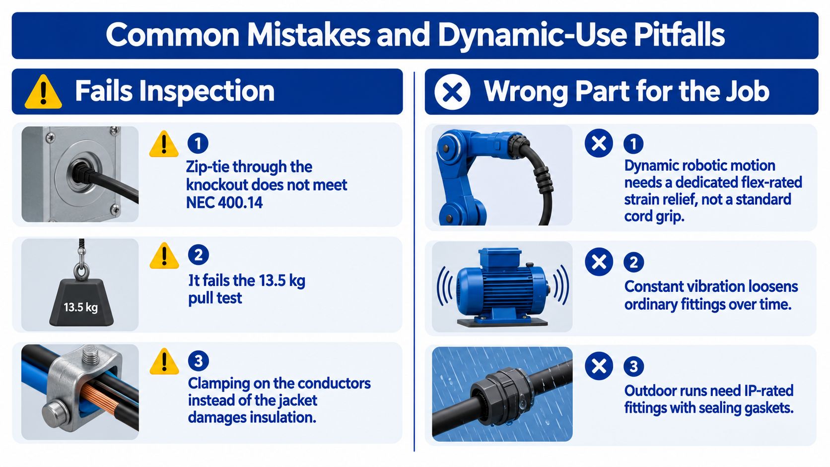
UL 514B is the U.S. fitting standard that matters at the point of installation. The 13.5 kg pull test described in field guidance is the practical verification method. The cable must stay put, and the jacket should show no slipping or obvious damage EDN cable strain relief selection. If the clamp bites the conductors or depends on friction alone, it is the wrong choice.
DIN EN 62444 matters on European machinery and metric installations because it sets the expectations for glands and retention. IPC/WHMA-A-620 sits behind the fitting and defines workmanship for the wire harness or cable assembly itself, so a good cord grip cannot make up for a poor termination.
A strong fitting protects a good termination. A weak fitting can ruin one.
Matching Threads, Materials, and Clamp Range to the Cable
A lot of bad selections happen before anyone looks at the cable. The fitter starts with the wrong knockout, then forces the wrong thread into it, then discovers the cable doesn't fit the clamp range anyway. Good procurement flips that order, first match the enclosure, then the thread system, then the material, and only then the clamp range.
Start with the thread system, not the catalog photo
NPT still dominates many U.S. enclosures, PG survives in legacy European hardware, and metric is the cleanest fit for IEC-style gear and a lot of imported panels. If the thread doesn't match the knockout, you've already created an adapter problem you didn't budget for. The practical rule is simple, match the enclosure hole pattern first, because a pretty gland body won't make a wrong thread work.
Then choose the body material for the environment
Nylon is fine in dry indoor cabinets, nickel-plated brass is a common step up for outdoor or washdown work, stainless 316 belongs in corrosive or food-grade environments, and PVDF is used where chemical exposure is the bigger threat. The material choice affects durability, sealing behavior, and service life, so the low-cost option isn't always the low-risk option. For cable sourcing and related fit-up decisions, buyers often review wire cords and cables alongside the fitting to keep the whole assembly consistent.
Clamp range has to follow cable OD
This is the part people miss. A 1/2" NPT cord grip with a 6 to 12 mm clamp range won't hold a 14 mm SOOW jacket, even if the thread looks right on paper. Put the cable outside diameter in the middle of the range when you can, because that usually gives the best seal and retention without crushing the jacket.
Cable / Enclosure
Thread
Material
Clamp Range
SOOW cord in a U.S. panel
NPT
Nylon or brass
Sized to the measured jacket OD
IEC machine lead in a metric enclosure
Metric
Nickel-plated brass or stainless 316
OD centered in the listed clamp span
Legacy European panel
PG
Brass or nickel-plated brass
Match jacket OD, not nominal cord size
Chemical washdown run
Metric
PVDF or stainless 316
Narrowest span that still centers the cable
Installing Wiring Strain Relief the Right Way
A good installation starts before the fitting is tightened. I have seen sound hardware fail because the installer stripped too much jacket, routed the cable after termination, or treated the clamp like a hole plug. The fitting only does its job when the cable sits on intact jacket and the body carries the retention load.
Confirm the knockout matches the thread, then have the locknut or sealing ring ready. Strip only enough jacket to reach the termination point, feed the cable through the body before landing the conductors, and seat the body against the enclosure wall before you snug the locknut. If the enclosure needs matching hardware, keep it on hand from the start through electrical boxes and accessories.
Torque deserves the same attention. Nylon bodies usually call for less tightening force than brass, and guessing can deform the jacket enough to weaken the grip. Once the body is set, the fitting should hold the cable without depending on terminal-side friction.
Verify the installation, don't assume it passed
Field verification starts with the pull test. As noted earlier, the common UL-style check uses a 13.5 kg load held for 1 minute, then looks for cable slip or jacket damage. The point is simple, the fitting must grip the jacket, not the conductors.
The bend geometry matters too. Keep enough radius for the cable type and duty cycle, since static runs and moving runs do not fail the same way. If the application flexes, add a service loop and clamp the trunk, not individual conductors. For sizing context on cord grips and enclosure fit-up, the same trade-offs are covered in EDN cable strain relief selection, but the installation itself still comes down to clean seating, correct torque, and a jacket that stays intact.
Document the install with a visible torque mark if your inspection process uses one. That gives the crew a fast way to confirm the fitting was tightened and checked, instead of just installed and forgotten.
Common Mistakes and Dynamic-Use Pitfalls
The most common mistakes are usually the ones people defend as “good enough.” A zip tie through the knockout looks tidy for about five minutes, then it starts failing the way the standards said it would, because it doesn't meet the code intent for strain relief and it won't pass a proper pull check. Mismatched threads create a different kind of failure, they may hold long enough to fool a quick inspection, then loosen under vibration or crack when the enclosure moves.
Where standard cord grips stop being the right answer
Ordinary dome-cap glands are fine for static cable. They're not the right choice for robotic tooling, repeated-axis motion, or any application where the cable moves with the machine over and over again. In those cases, the cable needs a flex-rated retention design or a gland built for repeated motion, because ordinary compression on a jacket that keeps bending will fatigue the jacket and the conductors inside.
If the cable already carries its own strain member, like some type W or stage-style assemblies, don't clamp that member the same way you would a simple jacketed cord. The strain member needs its own relief point inside the enclosure, otherwise the gland ends up taking a load it wasn't meant to carry. UV, oil, and heat also punish nylon faster than a lot of crews expect, so outdoor and process environments usually deserve a tougher material selection.
Practical rule: if the machine moves, the strain relief has to be selected for motion, not just for retention.
Procurement Checklist and Common Questions
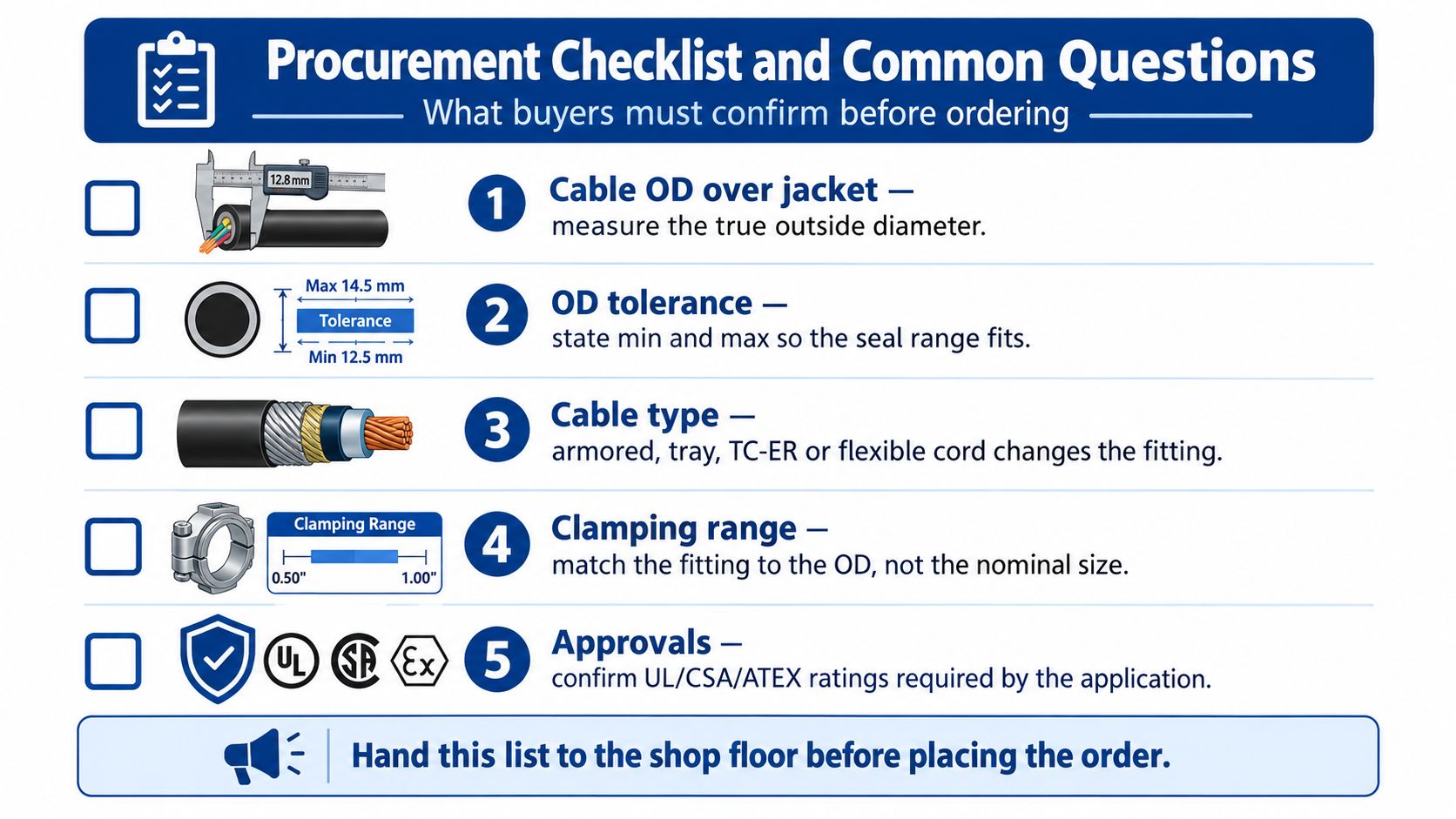
A bad order usually starts with a vague spec. Give purchasing the cable OD measured over the jacket, the thread standard, the enclosure hole size, the material, the indoor or outdoor rating, and whether the run is static or moving. That is the information that keeps the seal, clamp, and enclosure aligned with the job instead of forcing a field workaround.
What buyers should confirm before ordering
Cable OD over jacket: Measure the actual outside diameter, not the catalog name.
OD tolerance: State the minimum and maximum so the clamp range is usable.
Cable type: Armored, tray, TC-ER, and flexible cord all point to different fittings.
Connector thread and hole size: Confirm NPT, PG, or metric before the order goes out.
Approvals and environment: Check the enclosure rating, temperature range, and any UL, CSA, or ATEX requirements.
Common questions from the tech line
When is PG acceptable versus metric versus NPT? PG still belongs on some legacy and imported equipment, and that includes older Siemens-style panels where the hole pattern was built around PG hardware. Metric fits IEC-style panels cleanly, while NPT remains common on North American enclosures. If the thread is wrong, the job usually pays for it with an adapter, extra labor, and another leak point.
Can a standard cord grip hold a moving machine? It can hold the cable in place, but repeated flexing changes the story. Dynamic applications need a fitting rated for motion and a cable built for that duty, because a static grip tightened harder is not the same thing as a motion-rated solution.
What does the inspector want to see? The fitting should be listed for the use, the cable should be retained on the jacket, and the pull check should show no slip or conductor damage. The pull benchmark discussed earlier in the article is the practical reference people use to verify that the clamp is gripping the jacket correctly EDN cable strain relief selection.
If you need strain relief hardware, matching cable support, enclosure accessories, or help sorting through thread systems and compliance requirements, ATEK Distribution can help with sourcing and technical selection. Visit ATEK Distribution to review options and get the right parts lined up before the crew starts pulling cable.
You're at the supply counter with a material list in one hand and a route drawing in the other. The standard and tight-body fittings both say 90 degree elbow, both match the conduit trade size, and both appear suitable for the turn. The choice only becomes clear when you account for the cable pull, available clearance, utility requirements, and the inspection standard governing the job.
A 90 degree elbow conduit fitting redirects a raceway through a right angle while protecting conductors and preserving a usable path for installation. The catalog angle is only the starting point. Material, trade size, bend radius, body length, joining method, and the total bends in the run all affect whether the fitting works in the field.
What a 90 Degree Elbow Conduit Actually Does on a Job
A factory elbow controls more than the direction of a raceway. Its formed curve keeps the opening usable, protects conductors from sharp edges, and gives straight conduit a defined connection at each end. Those details affect whether a pull stays controlled or turns into a struggle at the enclosure.
The buying decision rests on four checks:
Material: Does the system use EMT, rigid metal conduit, IMC, PVC, or another approved raceway?
Radius: Is a standard sweep enough, or does the route require a long sweep or compact short-radius fitting?
Trade size: Does the elbow match the conduit and provide adequate interior space for the conductors?
Application: Will it be installed indoors, underground, outdoors, in a utility duct bank, or in a classified location?
Factory radius is fixed by trade size. It determines the clearance needed inside a panel, pull box, wall cavity, or equipment enclosure, and it affects the force required to pull conductors through the finished route. Exact steel EMT dimensions belong in the sizing table, but the purchasing decision starts here: a catalog angle does not describe how the elbow will behave during installation. Steel EMT elbow dimensions and bend radii
A field-bent 90-degree turn and a factory elbow may both satisfy the basic description, yet they can differ in consistency, clearance, and pulling performance. A utility inspector may also expect the listed fitting, approved joining method, and documented radius specified for the installation. Confirm those requirements before substituting one option for another.
Field rule: Check the material, trade size, published or stamped radius, listing, joining method, and project specification before the fitting reaches the cart.
If the raceway has not been selected, resolve the material first. If conductors must travel through the bend, evaluate the sweep and total route rather than the angle alone. Enclosure clearance and the complete run's bend count require their own checks.
Conduit Elbow Materials and Their Applications
Material selection comes before radius selection because each raceway family brings different mechanical, environmental, and installation requirements. A PVC elbow may be ideal underground but unsuitable where a metallic raceway is specified. An EMT elbow may be efficient above a commercial ceiling but a poor choice in an exposed, high-abuse area.
Steel EMT
Electrical metallic tubing, or EMT, is thin-wall steel tubing joined with setscrew or compression fittings. It's common in commercial interiors because it's relatively light, easy to route, and practical for exposed or concealed installations in permitted environments. Factory EMT elbows provide consistent geometry, but the installer still needs to confirm that the elbow's coupling style matches the straight conduit and the fittings used elsewhere in the run.
RMC and IMC
Rigid metal conduit, often called RMC or GRC, has a heavier wall and threaded connections. It suits locations where the raceway needs greater mechanical protection, including exterior routes, industrial areas, and portions of hazardous-location installations governed by the applicable NEC requirements. Intermediate metal conduit, or IMC, provides a metallic raceway option with less weight than RMC while retaining a threaded system.
Corrosion protection matters as much as wall strength. Galvanized finishes suit many general installations, while aluminum, stainless steel, or PVC-coated steel may be selected where moisture, chemicals, salt, washdown, or process conditions could attack ordinary steel. The exact fitting must be listed and approved for the environment, not merely described as corrosion resistant.
PVC Schedule 40 and Schedule 80
PVC is widely used underground and in corrosive environments because it doesn't rust and can be solvent-welded into a continuous raceway system. Schedule 40 is common where the project provides adequate protection, while Schedule 80 is selected where the installation needs a heavier wall or the specification requires it.
Manufacturer data for PVC Schedule 40 elbows identifies standard-radius 90-degree fittings listed to UL 651, with a 1-inch trade size elbow using a 5.75-inch bend radius. Larger trade sizes use larger geometry, and the fittings are factory formed for solvent-weld joining in the field. PVC Schedule 40 and Schedule 80 elbow data
Light and efficient, but less resistant to severe abuse
RMC or GRC
Article 344
Product-specific rigid metal conduit listings
Outdoor, industrial, exposed, and high-abuse areas
Strong and threaded, but heavier and more labor intensive
IMC
Article 342
Product-specific intermediate metal conduit listings
Industrial and exterior installations
Lighter than RMC, with threaded installation
PVC Schedule 40 or 80
Article 352
UL 651 is typical for listed PVC conduit products
Underground and corrosive environments
Corrosion resistant, but requires compatible solvent-weld installation
Material transitions need deliberate planning. A PVC underground route entering a building may transition to EMT or another metallic raceway, which creates questions about adapters, bonding, grounding, weather sealing, and fitting compatibility. Treat the elbow as part of the complete raceway assembly, not as an isolated plastic or metal curve.
Sweep vs Tight Radius Elbows and Why It Matters for Pulling
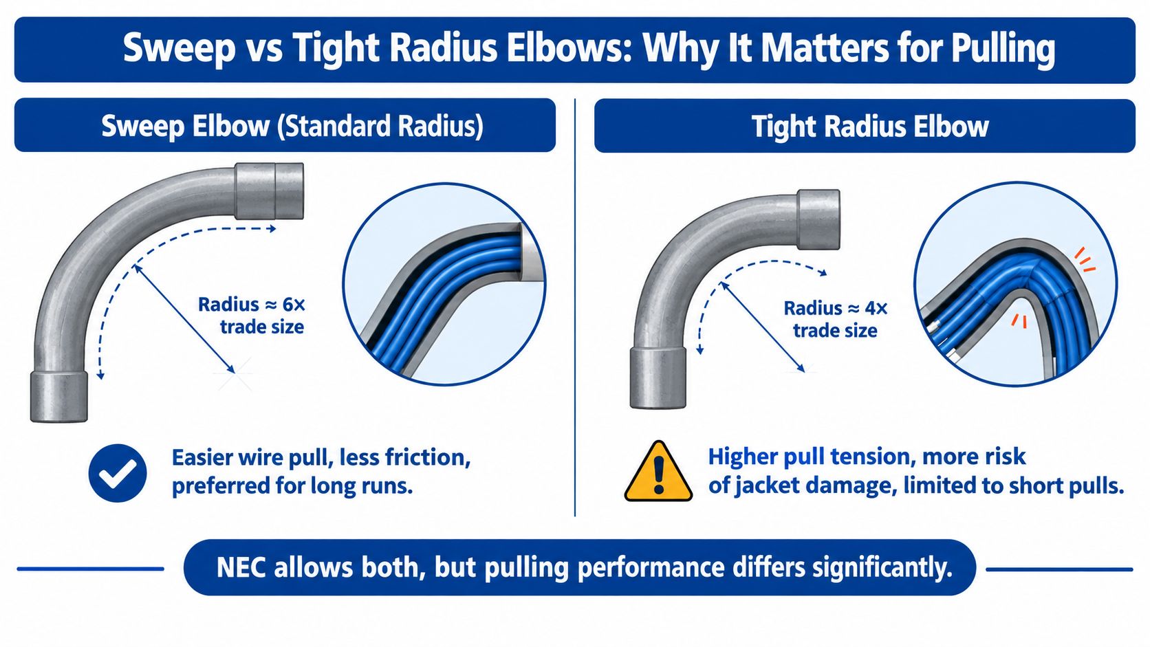
The biggest difference between a sweep elbow and a tight-radius elbow appears when conductors move through the finished raceway. A sweep elbow spreads the direction change over a broader curve. A tight-radius elbow saves space, but forces the conductors around a sharper path and can increase friction, pulling tension, and the chance of jacket or insulation damage.
A commonly used NEC-based training guideline places the inside radius of a 90-degree bend at least six times the conduit inside diameter. The purpose is practical. A smoother curve gives conductors a more gradual path and helps keep the conduit from deforming during bending. Conduit bending guidance and bend-radius principles
What works in ordinary routing
For most commercial and industrial raceways, a standard sweep is the safer default. It gives the pulling crew more room to work, reduces abrupt direction changes, and is easier to justify during inspection when the route has adequate space. Long sweeps are particularly useful where the run carries stiff conductors, larger cables, or a cable jacket that can be damaged by excessive sidewall pressure.
A tight-body elbow has a legitimate place. It can solve a clearance problem at a riser, enclosure, panel, or equipment entry where a broad sweep won't fit. The mistake is treating compact geometry as a universal substitute for a sweep. A fitting that fits the drawing may still make the completed pull unnecessarily difficult.
Where utility specifications change the answer
Code compliance is only the minimum threshold on many utility projects. PG&E specifies a 36-inch vertical radius for 2-inch and 3-inch primary conduit 90-degree bends, while some utility closeout specifications require long-sweep bends with a 60-inch minimum radius for changes of direction over 10 degrees. Those specifications may restrict short-radius manufactured elbows to riser applications. PG&E underground conduit requirements
That difference is why a generic product page isn't enough for utility work. Check the owner's standard, approved material list, duct-bank detail, and pull-box geometry before ordering. For a practical comparison of metallic raceway choices, see EMT versus rigid conduit differences.
Practical decision: Use a sweep unless the available space requires a tighter elbow and the project documents expressly permit it. For primary utility routes, follow the utility radius before relying on a general NEC minimum.
Sizing a 90 Degree Conduit Elbow for Your Run
A 90-degree elbow can fit the specified raceway and still fail the job in practice. Select it by trade size, connection method, bend radius, cable space, and the clearance needed to install and pull the run.
Trade size identifies the conduit system and nominal raceway size. Bend radius defines the curve through the elbow, affecting the physical envelope and the force required to move conductors. Start with the conduit specification, not the cable. A 1-inch EMT run requires an elbow made for 1-inch EMT with the correct connection method. An elbow made for PVC, RMC, or another trade size is not interchangeable just because it produces a 90-degree turn.
Use product geometry in the layout
Standard-radius steel EMT product data provides planning dimensions for the elbow centerline:
Use the radius to draw the centerline and outside envelope in the plan or coordination model. Add the radius plus half the conduit outside diameter to the centerline to estimate the outside envelope for clash detection. Check that envelope against panel interiors, box walls, framing, cable tray, access doors, and pull-box entries. The fitting may match the raceway while its body still collides with an enclosure or leaves too little straight length for the connection.
Verify conductors and fill
The elbow remains part of the same raceway system for conduit-fill purposes. Confirm conductor count, conductor dimensions, and available internal area under the applicable NEC requirements. Inspect the elbow's internal bore, particularly at the curve and connection, where a tight passage can increase pulling resistance or damage insulation.
A larger bend radius does not increase the conduit's internal area. If the conductors need more room, choose the correct larger trade size. A sweep can make the path easier without solving an undersized raceway.
Count the whole route
Mark every elbow, offset, kick, and field bend on the route drawing. Record the bend angles and the physical envelope, then verify that the planned pull point remains accessible before releasing material.
For a short interior run, elbow body depth may control the choice. On a long underground route, radius and pulling feasibility usually outweigh compactness. Factory elbows and field-bent alternatives may both qualify as 90-degree bends, yet their geometry can produce very different installation results. Choose the fitting that satisfies trade size, fill, clearance, radius, and project specifications together.
NEC Bend Limits and Compliance Planning for Conduit Runs
A conduit run can be individually correct at every elbow and still be poorly planned as a system. The controlling issue is the combined bend between accessible pull points, not just whether each fitting makes a clean right angle.
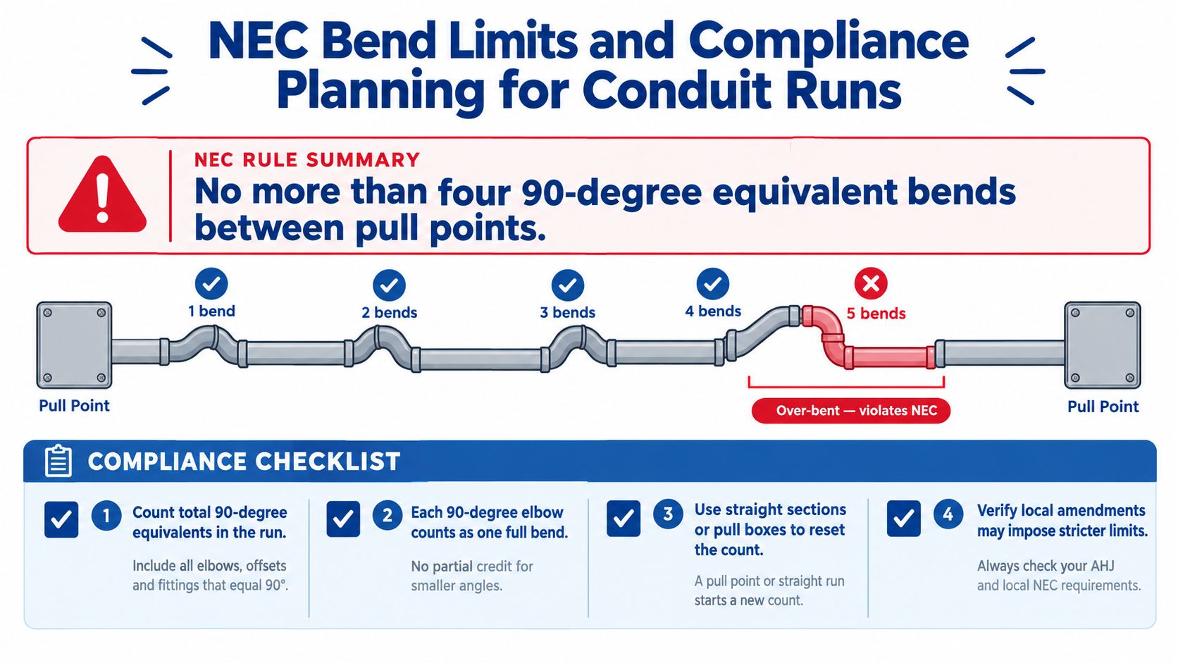
The NEC-based limit is 360 degrees between pull points, equivalent to four 90-degree elbows. A pull point may be a junction box, pull box, conduit body, or another permitted access fitting. NEC-based conduit bend-limit guidance
Track bend equivalents during design
A simple route worksheet prevents a common field failure. Start at the first pull point and list each direction change in order. Add the degrees for factory elbows and every component of field-made bends. Stop the count at the next accessible pull point, then begin a new segment.
This matters when a route combines a 90-degree factory elbow with offsets, kicks, or saddles. A run may look like a series of modest adjustments, but the total angle still accumulates. The installer who counts only the obvious 90-degree fittings can miss the contribution of smaller field bends.
Add access before the route becomes expensive
If the planned segment approaches the allowed bend total, add a pull box or conduit body during design rather than after the conduit is installed. The access point must be located where conductors can be pulled and where the box remains accessible under the project requirements.
Radius adds another layer. A route may stay within the total-degree limit while still requiring a larger utility-approved sweep or a different pull-box arrangement. Review bend accumulation, elbow radius, cable characteristics, and owner requirements together.
Planning habit: Put the bend count on the drawing before the first conduit is cut. It's cheaper to revise a route on paper than to add access after conductors are already staged.
Installing a 90 Degree Conduit Elbow Correctly
A factory elbow installs cleanly when the crew treats orientation, alignment, joining, and support as one operation. Rushing any one of those steps can leave a fitting that looks acceptable but creates trouble during the pull or inspection.
Confirm orientation before fastening
Dry-fit the elbow with the adjoining conduit before tightening anything. Check whether the turn is horizontal, vertical, or transitioning between planes. In a panel or equipment enclosure, rotate the elbow until the body clears the enclosure wall and the straight conduit lands without forcing the raceway sideways.
Cut conduit ends square and ream them thoroughly. A sharp edge inside the raceway can damage conductor insulation, while an unreamed end may prevent the conduit from seating fully in a connector or coupling.
Match the joining method to the material
EMT commonly uses either setscrew or compression fittings. Tighten them according to the fitting manufacturer's instructions. Over-torquing a setscrew can deform thin-wall EMT or damage the fitting, while under-tightening can leave the connection mechanically insecure.
RMC and IMC use threaded joints. Keep threads clean, use the specified sealing or corrosion-protection method, and maintain continuity and bonding as required by the installation. PVC uses solvent-weld connections. Clean and prepare the surfaces properly, apply the compatible cement, fully seat the joint, and allow the manufacturer's required set or cure time, especially in cold conditions.
Install supports near changes of direction in accordance with the NEC, manufacturer instructions, and the project specification. The elbow shouldn't carry the weight of an unsupported conduit run or become a lever against a box connector.
Before pulling conductors, inspect the complete interior path. Confirm that the elbow is seated, joints are secure, cut ends are smooth, the raceway is free of debris, and the conductor arrangement remains within permitted fill. A solvent-welded joint that hasn't set, an elbow installed out of plane, or a deformed EMT connection can turn a routine pull into a replacement job.
Use Cases by Application Type and Environment
The same right-angle geometry behaves differently depending on the surroundings, the owner's standard, and the consequences of a failed pull. Select the elbow after identifying the environment and the required raceway system.
Commercial offices and retail
EMT with standard sweep elbows is a practical choice for many indoor commercial routes, particularly above ceilings and in accessible service areas. The priority is usually efficient installation, clean alignment, and a pull path that doesn't punish the conductors. Compression fittings may suit locations exposed to moisture, while setscrew systems are common in dry interiors where permitted.
Industrial plants and manufacturing
Industrial routes often need more mechanical protection than light-wall EMT provides. RMC or IMC may be appropriate in exposed or high-abuse zones, near equipment, and where the raceway could face impact or harsh operating conditions. Use broad sweeps on longer cable routes, and reserve compact elbows for locations such as riser chases only when the design and specification support that choice.
Healthcare and clean environments
Healthcare, laboratory, and cleanroom projects place extra emphasis on cleanable surfaces, corrosion resistance, and predictable installation quality. Stainless steel, PVC-coated steel, or PVC may be selected according to the room classification, cleaning chemicals, moisture exposure, and owner standard. Avoid assuming that a fitting suitable for a general wet location satisfies a healthcare or cleanroom specification.
Underground and site utilities
PVC Schedule 40 or Schedule 80 sweep elbows are common in underground raceway systems, provided the product is listed for the installation and the route meets the project requirements. The elbow must align with duct-bank, encasement, burial, pull-box, and riser details. Solvent-weld preparation and joint setting deserve the same attention as the excavation and bedding.
Utility and primary distribution
Utility work is specification driven. Long-sweep elbows may be required even when a compact fitting appears to meet a general code rule. Review the utility's approved radius, material, riser limitations, pull-box details, and closeout requirements before procurement.
Hazardous and government facilities
Classified locations require listed fittings and raceway methods appropriate to the applicable hazardous-location rules. RMC with compatible listed fittings is frequently considered for these environments, but the classification and project documents control.
Government work can add sourcing and documentation requirements, including domestic-content provisions where applicable. Confirm listing certificates, submittals, approved manufacturers, and any Buy American Act or Trade Agreements Act requirements before ordering.
Quick Reference, Cross-References, and Key Terms
Buyer quick reference
Decision
Practical selection
Main check
Material
EMT, RMC, IMC, or listed PVC
Environment and joining method
Radius
Standard sweep, long sweep, or short radius
Pulling performance and owner specification
Trade size
Match the raceway system
Conduit fill and enclosure clearance
Application
Commercial, industrial, underground, utility, or classified
Listing, inspection, and project requirements
Related components
Conduit bodies: Provide an accessible change of direction and may serve as a pull point where permitted.
Pull boxes: Break up long or heavily bent routes and provide conductor-access space.
Couplings: Join straight conduit sections to elbows or other fittings.
Straps and supports: Hold the raceway in position and reduce stress at direction changes.
Junction boxes: Provide accessible connection or pulling locations when correctly sized and installed.
Key terms
Trade size: The nominal size designation used to identify the conduit system.
Bend radius: The radius of the elbow's curved path.
Sweep elbow: A fitting with a broader curve for easier pulling.
Short-radius elbow: A compact fitting with a sharper curve and tighter clearance needs.
Conduit fill: The amount of conductor area occupying the raceway.
Pull point: An accessible location where conductors can be installed or redirected.
Solvent weld: A PVC joining method that fuses prepared surfaces with compatible cement.
Setscrew fitting: A metallic fitting secured with screws that grip the conduit.
Compression fitting: A fitting that secures conduit through a compression mechanism.
NEC: The National Electrical Code, subject to the adopted edition and local amendments.
ATEK Distribution can help source conduit elbows, bends, couplings, supports, and related raceway components for EMT, PVC, rigid, and IMC systems, including technical documentation and alternate-product review when specifications or availability create a problem. For project-specific sourcing support, visit ATEK Distribution and send the conduit material, trade size, radius, application, and required listing.
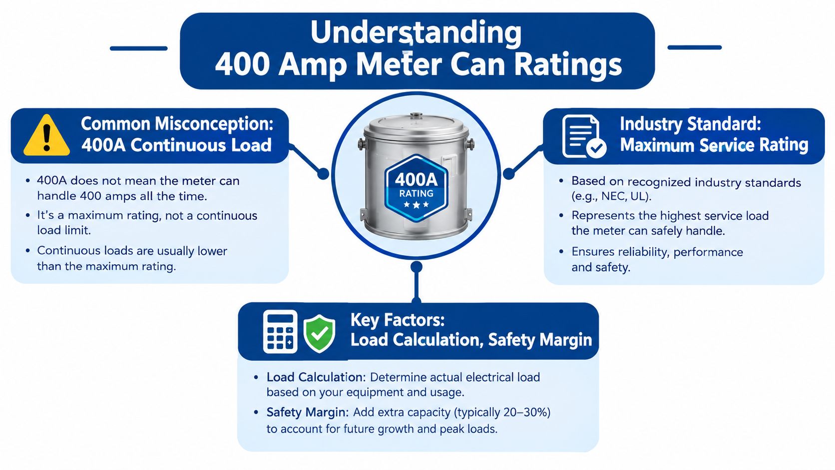
Most advice gets the first part wrong. A 400 amp meter can is usually not a true 400 amp continuous device, it's a 320/400 class meter socket that utilities accept as a 400 amp service point, while the continuous rating is commonly 320 amps. If you spec it as if it can carry 400 amps continuously, you can end up with a rejected submittal, a bad field install, or a service that the utility won't energize.
The label 400A is often misinterpreted. In utility practice, a 400 amp meter can is commonly a 320/400 amp class meter socket, which means the hardware may be accepted for 400 amp service without being rated for 400 amps continuous. That distinction matters before you order gear, because the utility, not the catalog title, decides what passes.
Read the rating the way the utility reads it
Skamania County PUD states that for 400-amp service, the required meter base is a Class 320 unit rated 120/240 volts and 320 amps continuous, with 4 jaws and a manual block bypass. It also says any structure needing more than 320 amps of continuous current requires CT metering instead Skamania County PUD guidance.
Practical rule: if the utility sheet says Class 320, spec and buy to that standard, not to the product headline.
That is why contractors have to read the nameplate, the utility service guide, and the approved equipment list together. A socket marked “400A” can still be a 320 continuous device with a 400 amp service rating. Those are not interchangeable terms.
Why the industry uses this convention
Utilities care about thermal limits and metering architecture. A socket can be acceptable for a 400 amp service while the meter element and service rules still cap continuous use at 320 amps. That is why many product listings and utility-approved standards use the same language instead of calling every large socket a true 400 amp continuous meter.
Legacy terminology adds another layer of confusion. A public utility approval document from 2018 says 400 Amp K-base meter socket[s] are no longer approved for several utilities, which shows how older forms were already being phased out by the late 2010s utility approval document.
A contractor who ignores this will often overspec the job and still miss the utility requirement. The safer approach is simple. Treat 400 amp as the service class, verify the continuous rating separately, and confirm the utility-approved configuration before ordering.
Why Continuous Versus Maximum Amperage Matters
A 400 amp meter can is often treated as if it means 400 amps continuous. In practice, the rating split matters more than the label on the cover. Many utility-approved self-contained sockets are sold as 400 amp service equipment while still carrying a 320 amp continuous limit, so the spec has to be checked against the service rules, not just the catalog title.
What changes in the field
That distinction affects load planning, conductor sizing, and protective device coordination. If the connected load will sit near the top of the continuous range for long periods, the utility may require a different metering arrangement instead of a larger-looking socket. Oversizing the can does not automatically increase usable capacity.
Utility acceptance is the decision point, not the catalog title.
Florida Power & Light's metering handbook requires 320-amp self-contained meters for all 400-amp services and prohibits K-base bolt-in meters, which is why the meter style matters as much as the socket body Florida Power & Light metering handbook. If the wrong configuration is ordered, the install can still fail review even when the rest of the work is clean.
Match the socket to the load profile
Contractors need to work from actual demand, not just service size. A large house, a light-commercial suite, or a mixed-load building may fit a 320A continuous / 400A class setup. Heavier or more sustained loading can push the project toward transformer-rated metering instead of a self-contained can.
Breaker selection belongs in the same review. Meter rating and overcurrent protection have to agree, especially when the service is split across panels or load centers. For a practical check on upstream protection choices, see circuit breaker selection considerations.
Self-Contained Versus CT Metering Options
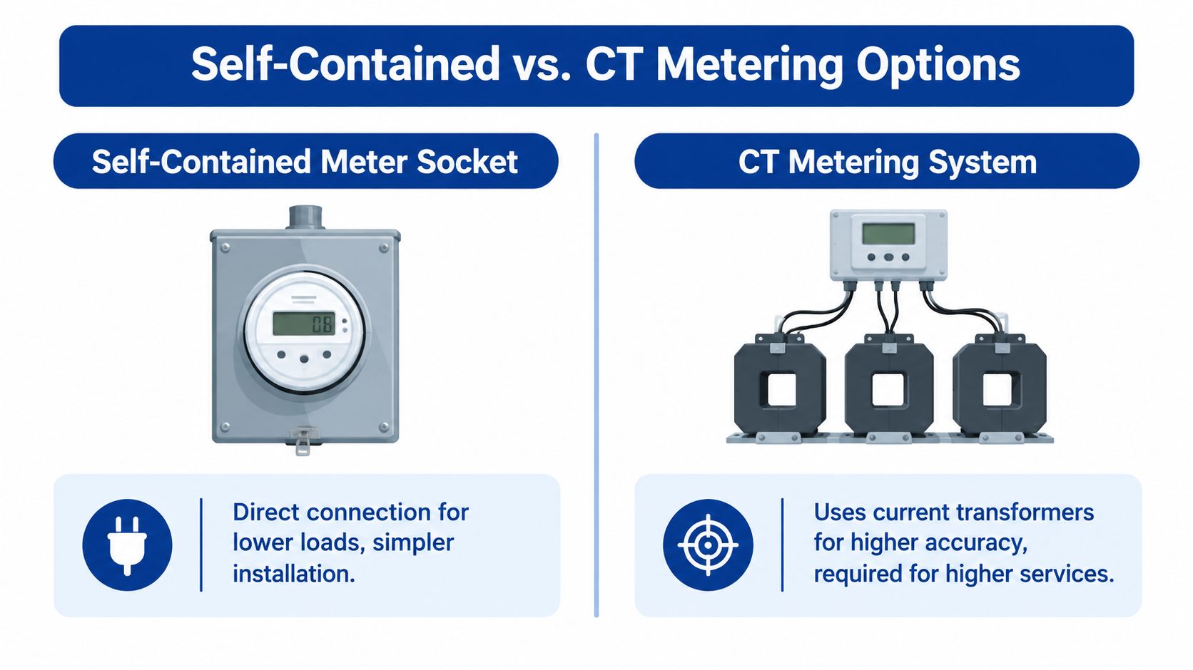
A lot of 400 amp calls get misread at the start. The label sounds like a physical size, but the core decision is whether the utility will accept a self-contained meter socket or require CT metering. That distinction matters because a 400 amp service often sits in the gray zone where the hardware title, the continuous rating, and the utility breakpoint do not mean the same thing.
Side-by-side differences that matter
A published utility detail from Lehi shows approximate enclosure dimensions of 5 in. D x 13 in. W x 19 in. H for an overhead-service meter socket up to 400 A, with concentric knockouts, utility-approved hub sizes from 1-1/4 in. to 2-1/2 in., and bypass required Lehi utility detail. That gives contractors a clear boundary, the self-contained option is a defined utility assembly, not a generic cabinet that can be adapted later.
The same detail says any service over 400 A must shift to current-transformer metering in factory-built CT cabinets or compartments, with NEMA 3R weather rating, installed ahead of the main disconnect unless the utility approves another arrangement Lehi utility detail. Once a project crosses that breakpoint, specifying a larger-looking socket does not solve the metering requirement.
How to choose the right architecture
Use self-contained gear only when the utility allows it and the load fits the accepted class. A house, a small commercial suite, or another moderate service may stay in that range, but a heavier or more sustained load can push the job into CT metering even if the service number still sounds like a “400 amp” job.
Load profile drives the decision as much as service size. A project with panels split across multiple load centers, or one with sustained high demand, needs the metering method and the protective devices reviewed together so the service arrangement stays inside utility rules.
Meter Can Mounting and Physical Specifications
A good 400 amp submittal often fails on geometry, not on theory. The can may be right in electrical terms and still be wrong in the field because the hub size, knockout layout, or weather rating doesn't fit the installation. Product documentation from distributor channels shows how often 400 amp meter can listings are described as 400A, 320 continuous, and sold under overlapping names like 400 amp meter, 320 amp can, 400 amp term can, and meter panRexel product listing.
What to verify before ordering
Start with enclosure type and mounting orientation. Overhead and underground services don't always use the same entry pattern, and a utility-approved can needs to line up with the service route, not the other way around. The wrong knockout placement can force a field modification that no inspector wants to see.
Next, check the weather enclosure and bypass provision. Outdoor meter sockets commonly need NEMA 3R protection, and the utility may expect a manual bypass or a specific ringless or ring-type setup depending on service rules. That's not a cosmetic preference, it's part of the approved configuration.
The submittal should prove fit, not just intent.
Why contractors get tripped up
The terminology is part of the problem. A buyer may ask for a “400 amp meter can,” receive a product marked 400A, and still end up with a 320 continuous device that's perfectly legitimate for the utility but not what the job was mentally modeled around. That gap is why field coordination gets messy.
For outdoor placements, enclosure selection matters as much as electrical rating. A practical reference for weather-exposed gear is how to choose electrical enclosures for outdoor use, because the meter can still has to survive the environment it's installed in.
Ring-Type and Ringless Meter Socket Configurations
Ring-type and ringless sockets solve the same basic job, but they handle utility access differently. The utility's sealing and removal process, the service entrance layout, and the approved equipment list all influence which one belongs on the project. If you pick the wrong style, the rest of the install can be clean and still not meet the utility's preference.
Ring-type sockets use a ring that secures the meter, while ringless designs rely on a different retention method. In practice, the utility's local standard usually decides the issue more than the contractor's preference does. That's why the approved list matters more than the catalog photos.
Choosing based on service design
Overhead and underground services can both use either configuration, depending on utility rules and product approval. The key is terminal compatibility and the service entrance method. If the utility wants a specific jaw arrangement or bypass style, that requirement outranks the general product family.
Contractors should also watch for matching jaw count, phase arrangement, and voltage class. The commonly accepted combinations in utility standards include 120/240 V single-phase and other approved variants, but the exact configuration must match the utility's list. A ringless unit is not automatically better, and a ring-type unit is not automatically older or less capable.
The right move is to spec the configuration the utility already accepts, then confirm that the service conductors and termination points align with that decision. Guessing here creates avoidable delays.
Meter-Main Integration and Future-Proofing
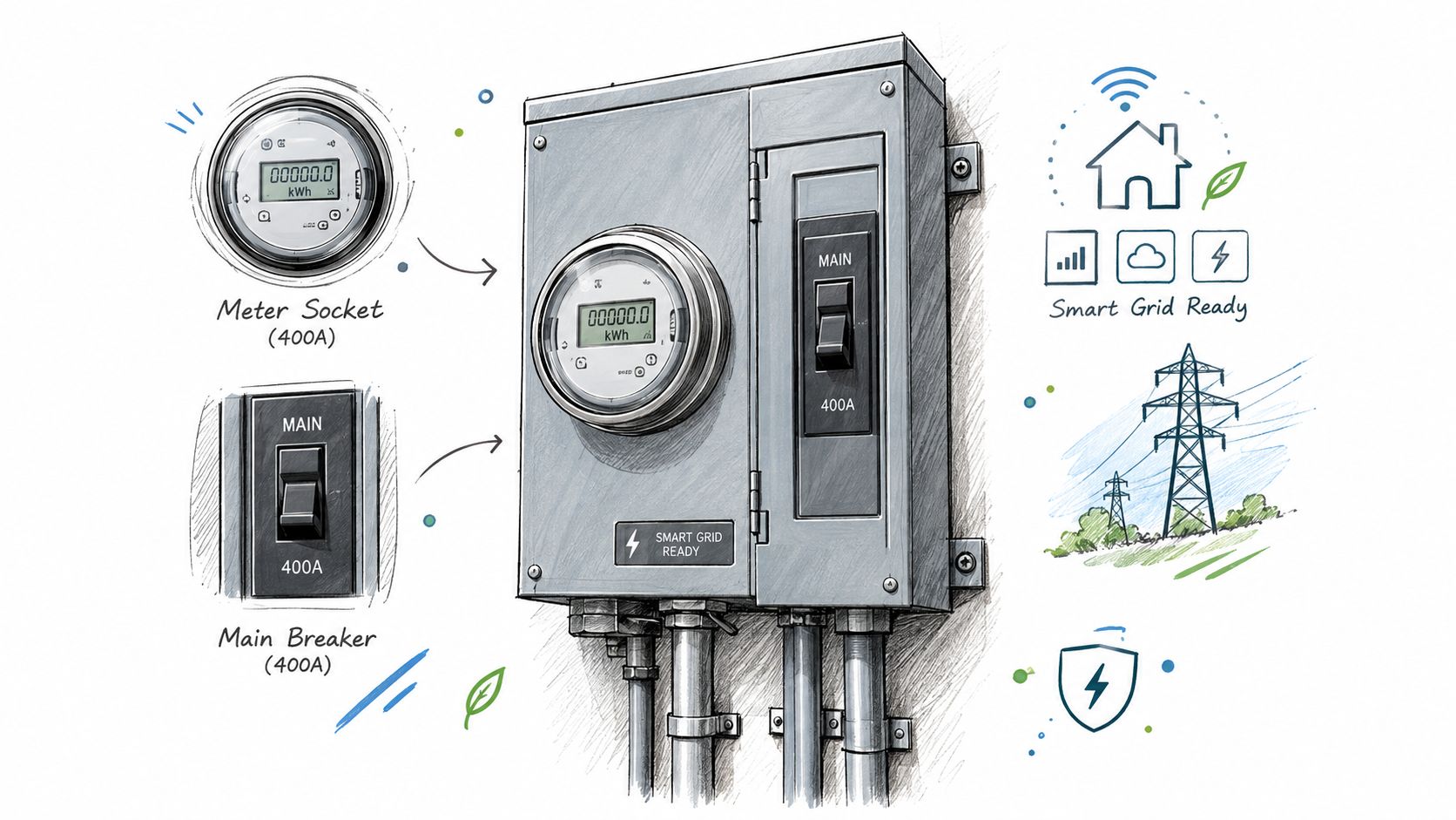
A standalone meter can solve only part of the service problem. Many projects now use meter-main combinations or integrated distribution gear because the service is no longer just feeding lights and receptacles. It also has to support EV charging, all-electric loads, backup-ready layouts, and, in some cases, temporary power or phased expansion.
Product listings and guides tie this category to EV-heavy homes, all-electric buildings, small commercial loads, and construction power Home Depot meter-main combo category. That does not mean every project needs combo gear. It means the buyer should match the hardware to the present load and the likely next step.
Think beyond the meter alone
The choice is between a standalone socket and an integrated assembly. If the install may later need extra disconnects, backup interfaces, or staged load management, meter-main gear can reduce rework. If the service is straightforward and the utility wants a simple self-contained arrangement, a standalone can still be the cleanest option.
I've seen contractors choose for today's load and ignore tomorrow's additions. On electrification-driven jobs, that creates avoidable changes later. The client may not know whether solar, storage, or EV charging will be added next, but the service equipment should leave room for those decisions.
For projects that need metering strategy, utility coordination, and procurement support, ATEK Distribution can source meter sockets and meter centers for commercial, industrial, and government electrical work. Their team also handles technical review and RFQ-based sourcing, which helps when the project needs the right configuration instead of a generic part number.
Quick Reference Selection Guide
The fastest way to avoid a bad order is to match the project type to the utility-approved configuration before you look at price or lead time. A 400 amp meter can is not one universal product. It's a family of configurations that change based on load profile, phase, bypass style, and whether the utility wants self-contained or CT metering.
Selection cues that usually matter
Single-family or light-commercial with standard utility acceptance: A 320/400 class self-contained socket is often the starting point, but only if the utility allows that arrangement.
Higher sustained load or utility breakpoint exceeded: Move toward CT metering rather than forcing a bigger-looking self-contained can.
Overhead service: Confirm hub size, entry orientation, and bypass requirements before you order.
Underground service: Verify the enclosure layout and termination access, not just the amperage label.
Ring-type versus ringless: Use the utility-approved style, not the style that happens to be in stock.
Future add-ons like EV, solar, or storage: Favor a service architecture that won't be ripped out when the load grows.
What to verify on every submittal
Check the amp class, the continuous rating, the jaw count, the voltage, the bypass method, and the enclosure rating. Then confirm that the service architecture matches the utility's metering rules and the site's actual load plan. If any one of those items is unclear, the order isn't ready.
A simple rule keeps projects moving. If the product name says 400A but the utility sheet says Class 320, the utility sheet wins. If the site load exceeds the self-contained threshold, stop treating the can as the answer.
Utility Compliance and Submittal Requirements
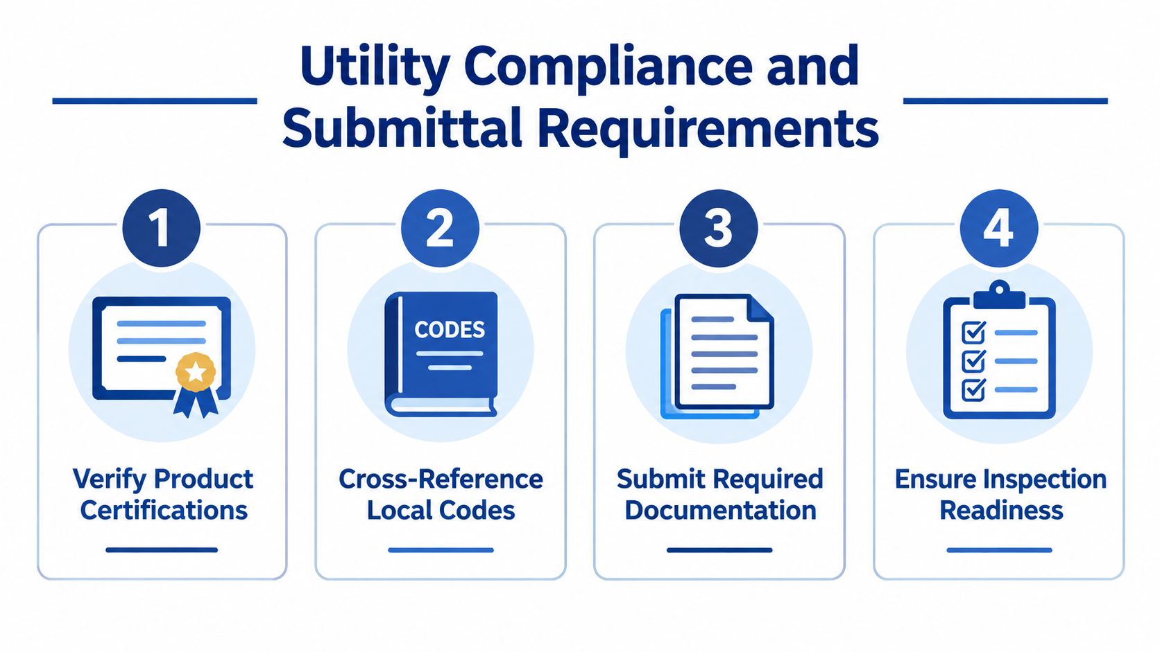
A compliant 400 amp submittal starts with the utility-approved list, not the distributor catalog. The utility decides what it will energize, and the inspector checks whether the installed hardware matches that decision. Legacy gear can disappear from approval quickly, so a familiar form is not enough if the utility has moved on.
Build the submittal around the utility file
First, verify that the exact meter socket or CT equipment is on the approved list. Then cross-check the local service standard and any municipal detail sheets. After that, submit the product cut sheet and make sure the ratings on the sheet match the utility's language, not just the seller's shorthand.
Check inspection readiness before the truck rolls. The bypass requirement should be satisfied, the enclosure type should be correct, and the service configuration should match the approved architecture. If the utility wants NEMA 3R or a particular jaw arrangement, that detail belongs in the submittal package, not in a note the reviewer has to hunt for.
The best submittal is the one that answers the utility's question before they ask it.
Avoid the classic documentation failures
The most common failure is a mismatch between the catalog description and the utility's terminology. Another is assuming an old approved form still passes because it looks familiar. Utilities update standards, and field crews do not get to negotiate after the fact.
A K-base example makes the point clearly. A form that was once common can fall out of approval, so the safe move is to verify the current utility sheet before you release the order.
Keep one clean packet for the meter socket, one for the service conductors, and one for the disconnecting means. That makes it easier for the AHJ and the utility to verify the whole service path without sorting through mixed paperwork.
Common Mistakes and Best Practices
The worst mistakes with a 400 amp meter can are simple and expensive. Contractors either buy to the marketing headline, ignore the utility's class language, or assume that a bigger socket automatically means more usable service. None of those shortcuts helps once the utility reviews the job.
What trips jobs up
Buying by product title alone: A listing that says 400A may still be a 320 continuous socket, so the title can't be the only decision point.
Skipping utility verification: If the utility wants Class 320, ringless, or CT metering, that rule controls the job.
Missing bypass requirements: Some service standards require a manual bypass, and leaving it out can kill the submittal.
Using the wrong legacy form: Older K-base equipment may already be out of approval in some jurisdictions.
Ignoring future load growth: EV charging, all-electric equipment, or added distribution can change the right metering architecture later.
What experienced specifiers do differently
They read the utility sheet first, then compare the product cut sheet against it. They confirm the continuous rating separately from the service rating. They also check whether the project belongs in the self-contained category or the CT category before they write the purchase order.
A practical habit is to treat the meter can as part of a system, not a standalone purchase. The socket, the service conductors, the disconnects, and the utility requirements all have to line up. If one piece is off, the whole package slows down.
Contractors who get this right usually save the most time at the review stage, not during installation. The field work becomes routine because the paperwork already matches the hardware.
If you're sourcing a 400 amp meter can, meter-main combo, or related service equipment for a project that needs the right utility-approved configuration, start with ATEK Distribution. They help contractors, engineers, and procurement teams source electrical distribution products and support submittals with technical review, which is exactly the kind of help that keeps a service upgrade from turning into a rework cycle.
You're standing in a trench or a handhole, the old splice is wet, the jacket is brittle, and the customer wants the circuit back before the end of the day. That's where underground wire splice kits stop being a catalog item and start being a decision about moisture, location, conductor type, and whether the splice can survive the next season without another dig-up.
The mistake I see most often is treating the kit as the whole solution. A good underground splice still fails if the location is wrong, the conductor match is wrong, or the sealing method is rushed.
Why Underground Splices Fail and What a Kit Must Do
A buried splice usually does not fail because the brand was wrong. It fails because water, dirt, or a poor enclosure got to it, and the repair stayed buried long enough for the connection to deteriorate.
The failure often starts before the splice itself
I have pulled up direct-burial repairs that looked fine on day one and later found failed because the enclosure never sealed properly, the conductors were not cleaned well, or the splice was placed where it should have been treated as inaccessible. Utility field reporting on underground fiber work points to about 28% of installation issues coming from splicing and splice-case problems, with poor cleanliness, rushing, and weak sealing repeatedly named as failure points (UTC underground fiber report).
Practical rule: If a splice is going to live in wet soil, the kit must do more than connect conductors. It has to keep water out, hold insulation integrity, and stay sealed after the trench is closed.
That standard has been built over time. A 1976 technical note traced premolded and slip-on cable splices for solid-dielectric insulated cables back to the 1950s, with standard publications cited in 1969 and 1971 for rubber-insulated and cross-linked polyethylene-insulated systems, which shows that modern underground splice-kit design grew out of decades of utility cable development (CSA cable standards reference). The point is simple. Underground wire splice kits still have to survive moisture, burial, and long service without opening up.
Location compliance matters as much as sealing
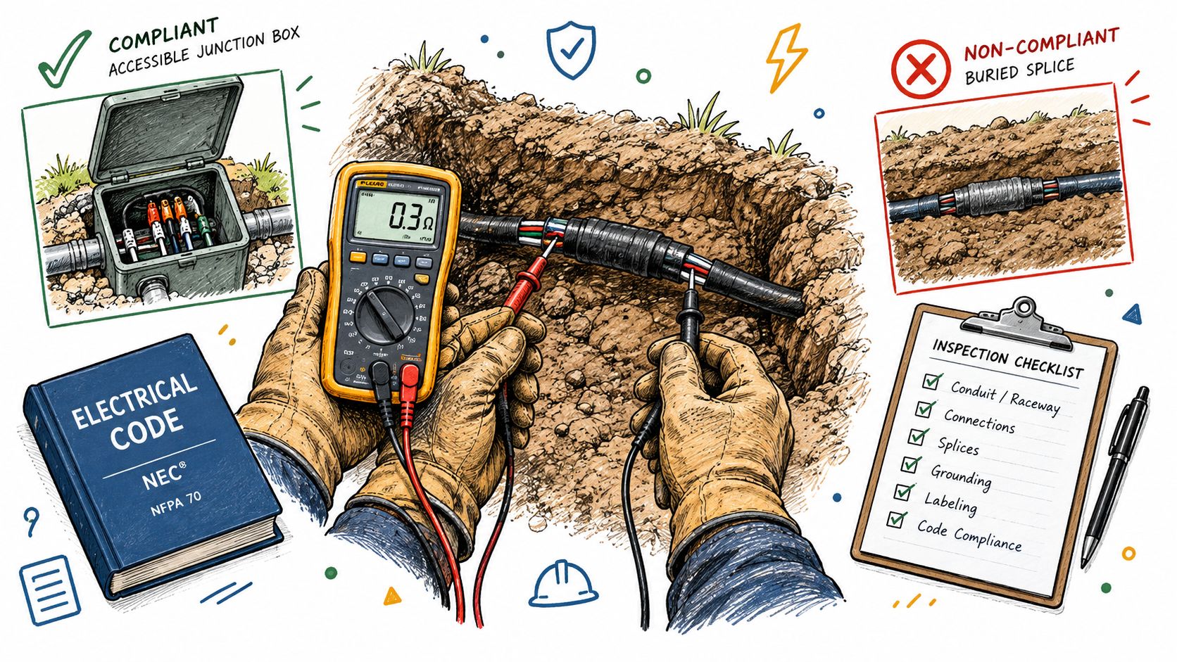
Retail listings like to say watertight or submersible. Utility specs are stricter. Utility and government specifications commonly restrict splices to accessible locations such as manholes, handholes, or pedestals, because a buried splice that cannot be reached becomes a maintenance problem and often a compliance problem too.
That gap catches a lot of buyers off guard.
A kit also has to match the conductor type, because copper and aluminum do not tolerate the same hardware or prep. Shielded cables add another layer, since the shield path has to stay intact through the splice instead of being treated as an afterthought. If the kit is meant for the wrong conductor, or the shielding path is handled poorly, the splice may still be buried, but it will not be dependable.
For procurement, I look at three questions first. Can the splice stay dry in the soil conditions? Can it be placed where the spec allows? Can it match the conductor and cable construction on the job? If any answer is weak, the kit is only part of the fix.
Comparing Underground Splice Kit Types and Sealing Technologies
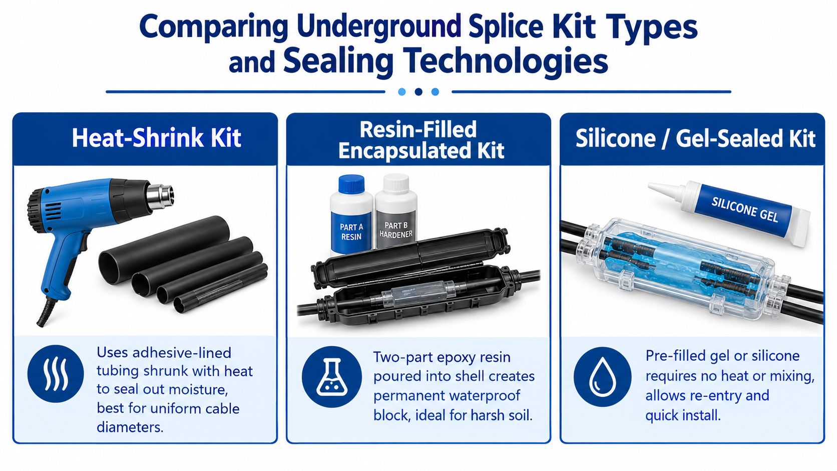
The category looks simple on a product page, but the sealing method changes how the splice behaves in the ground. Heat-shrink, resin-filled encapsulated kits, and silicone or gel-sealed kits all solve the same problem differently, and they don't fail in the same way.
Three sealing methods, three very different jobsite realities
Kit Type
Sealing Method
Best Use Case
Trade-off
Heat-Shrink
Adhesive-lined tubing shrinks with heat and bonds around the splice
Uniform cable diameters, controlled installs, work that needs a compact finished profile
Needs heat, clean prep, and enough room to work without scorching or underheating
Resin-Filled Encapsulated
Two-part resin or epoxy is poured into a shell and cures around the splice
Harsh soil, wet locations, and places where long-term sealing matters more than speed
More permanent, slower to install, and messy if the enclosure isn't positioned correctly
Silicone or Gel-Sealed
Pre-filled gel or silicone blocks moisture without heat or mixing
Quick repairs, re-entry needs, and jobs where speed matters
Usually easier to install, but the sealing system still depends on correct conductor fit and enclosure closure
What each type is good at, and where it disappoints
Heat-shrink kits are popular because they're tidy and familiar. They work well when the cable diameter is predictable and the installer can heat the tubing evenly, but they're less forgiving if the work area is cramped or the cable jacket is contaminated.
Resin-filled kits are the old reliable choice for ugly environments. Once they're cured, they give a permanent waterproof block, which is why they make sense in harsh soil or wet conditions. The trade-off is simple, they're less forgiving during install, and once poured and set, you're not opening them casually.
Silicone or gel-sealed kits win when time matters and you might need to re-enter later. They're fast, they avoid torching or heating in awkward places, and they reduce the chance of installer error caused by a rushed resin mix. The catch is that “fast” doesn't mean “unimportant”, the conductor still has to fit, the enclosure still has to close correctly, and the application still has to allow that style of splice.
The right kit is the one that matches the environment you actually have, not the one with the best retail headline.
For procurement teams, the category is still active and broadening across heat-shrink, resin-filled, and silicone-seal formats, but the key decision is whether the kit's sealing method fits the burial condition and the maintenance expectation. If a splice may need to be opened later, don't buy a system that behaves like a permanent potting block unless the spec calls for exactly that.
How to Select the Right Kit for Your Conductors and Environment
Most ordering mistakes happen before anyone opens the box. The wire fits, the connector looks right, and then the kit is wrong for the conductor material, cable construction, or environment.
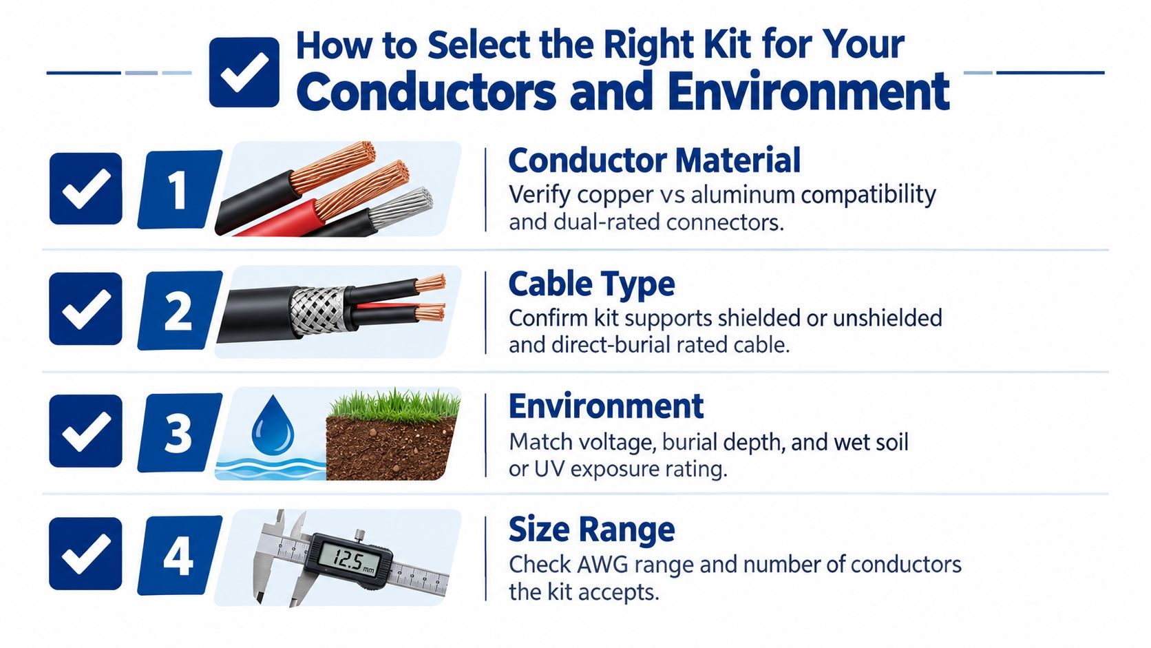
Start with conductor material, not packaging language
Copper and aluminum are not interchangeable in practice. A kit that works on copper branch circuits may not be acceptable on a larger feeder, and a conductor-specific SKU can be the difference between a clean install and a return trip.
The ideal order check is straightforward:
Verify the conductor metal. Make sure the kit is listed for copper, aluminum, or both, because material mismatch changes connector behavior.
Confirm the cable style. Shielded and unshielded cables don't always use the same accessories, and direct-burial rating isn't automatic.
Match the size range. A kit built for small UF branch circuits is not the same product as a larger feeder kit.
Check the environment. Wet soil, direct burial, and exposure conditions should be part of the selection, not an afterthought.
A quick example makes the point. A UF kit rated for #14 to 8 AWG copper is not a substitute for a 1/0 to 250 MCM Al/Cu kit. Those are different jobs, different connector geometries, and different failure risks. The current product category shows the category split across narrow SKUs, with some kits aimed at small copper conductors and others built for larger aluminum or copper ranges (IDEAL product listings).
Compare the application to the listing, not just the wire size
The right kit has to fit more than the conductor barrel. It also has to fit the way the cable will live in the ground. Soil movement, moisture, and burial depth affect whether a splice should be treated as a simple connection or as part of a sealed system that has to hold up over time.
If you're working on an outdoor branch circuit or a feeder, check the listing for direct-burial suitability, wet-location use, and the number of conductors the kit accepts. If shielded cable is involved, don't assume a generic kit will handle it cleanly.
For buyers who need a broader electrical sourcing path, ATEK Distribution is one place to compare connectors, wire termination parts, and related supplies without starting from a random retail listing.
Field note: If the product page doesn't clearly state conductor material, size range, and burial suitability, treat that as a warning, not a gap to guess through.
Installing an Underground Splice Kit for a Watertight Seal
A splice can look fine on the bench and still fail in the trench if the work is rushed. Wet jacket surfaces, dirt in the connector area, or a poor heat cycle will defeat a good kit fast.
Clean prep is where most of the job is won
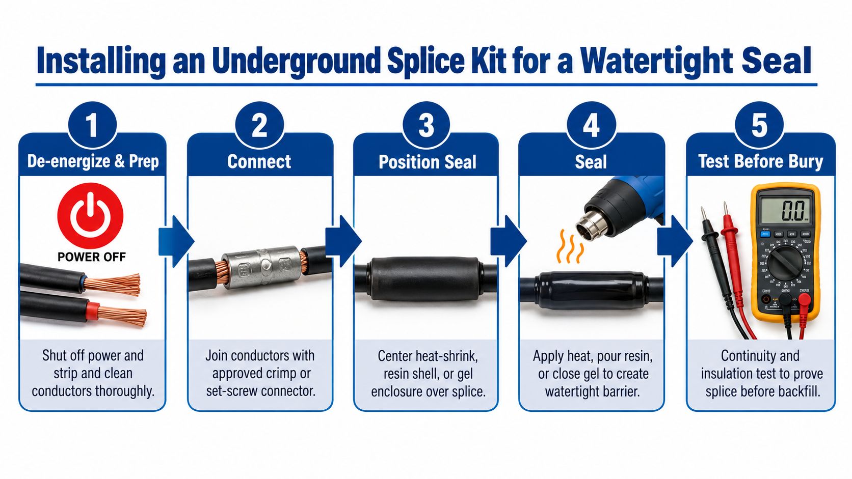
De-energize the circuit first, then strip, clean, and dry the conductors before you make the mechanical connection. As noted earlier, poor cleanliness and rushed work are major contributors to splice problems, which is why the connection has to be built on a clean, dry surface before any sealing step starts.
Use the connector the kit specifies, and torque it the way the manufacturer intends. A loose crimp or an under-set screw leaves heat and resistance inside the splice, and a perfect outer seal will only hide that mistake until the fault shows up later.
Seal in the right order and protect the assembly
Once the conductors are joined, center the enclosure or tubing over the splice before you seal it. Heat-shrink kits need even heating across the full recovery area, not a quick pass that leaves cold spots. Resin kits need the two-part mix handled cleanly and given the full cure time before burial. Gel and silicone kits need the housing fully closed, with no debris or pinch points at the gasket.
Match the install method to the site. In a trench, mud and standing water make sloppy sealing harder to recover from. In a handhole, keep the splice positioned so it is not sitting in water if the layout allows that choice. If the splice shares space with adjacent outdoor gear, electrical enclosure selection for outdoor use matters because a bad enclosure choice can compromise the whole assembly.
Do not backfill a splice you have not inspected in your hands. If you cannot see the seal, you are trusting the trench instead of the work.
A short process video can help crews standardize the method before they start work on site.
Before the trench closes, do a continuity check, verify the seal is seated, and confirm the splice is not twisted or crushed by the backfill path. For shielded cable, also confirm the shield is handled the way the kit calls for, since a watertight shell does not fix a poor shield termination.
Where You Can Legally Place Splices and How to Test Them
A splice can pass an electrical check and still fail the job if it sits in the wrong location. That is the part retail product pages usually skip, and the part inspectors and utility specs focus on first.
Retail claims are not the same as field approval
Many listings use direct-burial, watertight, or submersible language. Field specs are often tighter. Government and utility documents commonly push splice locations into accessible manholes, handholes, or pedestals, and some work also has to meet immersion requirements instead of simple wet-location exposure (DoD UFGS splice guidance).
That is why location comes first. A kit can be well made and still miss the spec if it cannot be reached for inspection or service. In utility work, access is part of compliance.
Test before the backfill makes the evidence disappear
Once the splice is complete, inspect the seal in hand, then test the circuit before burial. Use a low-resistance ohmmeter for continuity, then apply insulation resistance testing at 500V or 1000V if the manufacturer allows it. Catch the fault now, before soil and time hide it.
For shielded cable, confirm the shield is terminated the way the kit requires. A sealed housing does not fix a poor shield connection, and a good-looking splice can still fail electrically if the shield path is wrong.
Document the work before backfill. Record the kit type, conductor range, installation point, and the handhole or GPS reference so the splice can be found later without guesswork. If the job also depends on enclosure compatibility, electrical boxes and related hardware belongs in the same review, because the splice location and the enclosure choice affect each other.
If the splice cannot be inspected or retested later, the standard has to be tighter on day one.
Final Checklist for Reliable Underground Splices
A dependable underground splice comes from three filters, not one. First, pick the right kit technology for the environment. Second, match the kit to the conductor material, size, and cable type. Third, install it cleanly and test it before the trench disappears.
The bigger lesson is simple. Watertight on a retail page is not the same thing as compliant in the field. In weather-exposed or direct-burial work, the expectation is a sealed system that holds up under moisture, burial stress, and whatever the enclosure sees after the backfill goes in.
If the selection is unclear, or if the project needs alternate sourcing, compliance paperwork, or a substitute that matches the spec without slowing the job, that's the point to involve a distributor who works upstream of the box. ATEK Distribution helps contractors and procurement teams source electrical products, compare options, and keep mission-critical work moving when the specification is tight or the lead time is not.
If you're sourcing underground wire splice kits for a project, visit ATEK Distribution to compare electrical connectors, wire termination supplies, and related enclosure options in one place. If you need help matching conductor type, burial rating, or compliance documentation, their team can support the procurement side while you keep the install moving.
You're looking for “mega lugs for PVC,” but the first question isn't the pipe size. It's which PVC system you're working on. In water and wastewater construction, MEGALUG usually means a mechanical-joint restraint for PVC pressure pipe. In electrical work, PVC usually means conduit, and the required fittings are couplings, connectors, bodies, sweeps, adapters, or bushings. Those are different product categories with different installation methods.
That distinction matters before anyone orders material. A restraint gland for a mechanical-joint bell won't replace an electrical conduit fitting, and an electrical conduit accessory won't restrain a pressurized water main. The guide below focuses on EBAA Iron MEGALUG mechanical-joint restraint for PVC pressure pipe, including product families, pipe standards, sizing, gasket selection, torque, and field installation.
MEGALUG is a registered EBAA Iron product family, not a generic name for every PVC lug or a fitting used with electrical conduit. The product is a mechanical-joint restraint gland designed for PVC pressure pipe used with compatible mechanical-joint bells. EBAA Iron's documentation identifies the Series 2000PV for C900, C905, and IPS OD PVC pipe, with product sizes extending from 3 inches through 36 inches and larger-diameter versions reaching 42 inches and 48 inches in the broader product family (Series 2000PV PVC MEGALUG specifications).
The fitting has a segmented gland ring, gripping wedges, and side bolts that engage the mechanical-joint flange bolt circle. Once assembled correctly, the wedges grip the pipe while the gland transfers axial force into the joint hardware. The restraint therefore addresses pipe movement at a joint, rather than sealing the joint against leakage.
The two PVC meanings buyers commonly mix up
A waterworks buyer is usually searching for restraint on:
AWWA C900 PVC pressure pipe
AWWA C905 PVC pressure pipe
IPS OD PVC pressure pipe
Compatible mechanical-joint fittings and appurtenances
An electrical contractor may instead be searching for a fitting for PVC conduit, cable routing, or a duct bank. That work uses conduit-specific components, not a pressure-pipe restraint gland. Mechanical-joint restraint also isn't a method for pulling wire through conduit or joining cement-welded conduit sections.
In practical terms, MEGALUG can reduce dependence on concrete thrust blocks where the design permits restrained joints. That can help on congested easements, inside casings, or in soils where excavation and bearing conditions complicate a conventional block. It doesn't eliminate engineering review. The pipe standard, outside diameter, bell dimensions, gasket, joint configuration, and installation instructions still control.
Practical rule: Start with the pipe print line and joint type. Don't start with the word “PVC” in a search box.
The remaining selection process is straightforward. Identify the pipe standard, verify the outside diameter, choose the matching Series 2000PV family, then confirm gasket and torque requirements before assembly.
The MEGALUG Product Families at a Glance
The Series 2000PV family scales with the pipe, but it isn't one universal gland that fits every PVC dimension. The key procurement mistake is treating nominal size as sufficient. Nominal size only becomes useful after it's matched to the pipe's outside-diameter basis and mechanical-joint configuration.
The published product information supports a range from 3 inches through 36 inches, with larger installations extending to 42 inches and 48 inches (EBAA Iron Series 2000PV product information). The broad selection logic looks like this:
Family
Nominal Size Range
Pipe Standards
Bolt Size
Series 2000PV, smaller sizes
3 to 12 inches
C900, C905, and IPS OD PVC where specified
Published product data identifies smaller restraint hardware, including 3/4-inch T-bolts
Series 2000PV, mid-range sizes
14 to 36 inches
Primarily larger-diameter C905 and compatible AWWA PVC applications
Published product data identifies larger hardware, including 1-inch bolts in the mid-range
Mega Series, large diameter
42 to 48 inches
Large-diameter C905 PVC applications
Heavier hardware, with published torque ranges of 120 to 150 ft-lbs for these sizes (PVC MEGALUG data sheet)
The smaller range is where C900 and IPS OD PVC commonly overlap in nominal size. That overlap doesn't mean the pipes have identical dimensions. The gland body may be selected by nominal size, while the gasket and pipe OD determine whether the assembly is compatible.
The 14- to 36-inch range addresses larger PVC pressure pipe, particularly C905 dimensions that follow a ductile-iron-pipe-equivalent outside diameter. The 42- and 48-inch versions are intended for major transmission applications and require closer attention to hardware, torque, joint design, and field access.
Treat the product family as a system of matched components. The bell, gland, bolts, wedges, gasket, pipe OD, and installation procedure must agree. A correct nominal size paired with the wrong OD basis is still a wrong selection.
Pipe Standards MEGALUG Is Designed For
The pipe standard tells you more than the material. It also points to the dimensional system that the restraint must grip. For PVC pressure pipe, the important distinction is between C900, C905, and IPS OD dimensions.
Nominal Size
Pipe Standard
OD Basis
MEGALUG Family
4 to 12 inches
AWWA C900 PVC
C900 outside diameter
Series 2000PV smaller sizes
4 to 12 inches
IPS OD PVC
Iron-pipe-size outside diameter
Series 2000PV IPS-compatible selection
14 to 48 inches
AWWA C905 PVC
Larger-diameter AWWA PVC, commonly aligned with ductile-iron-equivalent joint dimensions
Series 2000PV mid-range or large-diameter Mega Series
Matching mechanical-joint fittings
Ductile iron
Mechanical-joint bell dimensions
Compatible restraint selected for the actual pipe and joint
The transition between 12 inches and 14 inches deserves special attention. C900 and C905 aren't interchangeable dimensionally because both are PVC pressure-pipe standards. An IPS OD pipe in that area also shouldn't be assumed to match a restraint designed around a ductile-iron-equivalent outside diameter.
A MEGALUG must grip the actual spigot OD, and the bell must accept the selected joint hardware. The product documentation identifies compatibility with C900, C905, and IPS OD PVC, but the specific catalog size and gasket still need to match the pipe on the project (Series 2000PV PVC restraint documentation).
For electrical projects, use conduit-specific catalog categories instead. ATEK's PVC electrical conduit fittings cover the type of couplings, connectors, elbows, adapters, reducers, and bushings used to build conduit systems. Those products serve a different installation purpose and shouldn't be substituted for pressure-pipe restraint.
Sizing a MEGALUG to Your PVC Pipe
Order from the pipe, not from memory and not only from the purchase order. The installer should confirm three items before selecting a gland:
Nominal pipe size
Outside diameter at the spigot
Pipe standard printed on the barrel
The print line is especially valuable because C900, C905, and IPS OD PVC can share nominal sizes while using different dimensional conventions. A tape measure helps verify the physical pipe, but it doesn't replace the standard, DR, or manufacturer identification.
A practical field check
Clean the area where the gland will seat, then inspect the pipe for gouges, raised material, dirt, or damage that could interfere with the wedges or gasket. Measure the barrel OD where the restraint will engage, rather than measuring a bell, coupling, or protective coating.
Nominal Size (in)
Pipe Standard
Series 2000PV Size
Note
3 to 12
C900 or compatible PVC selection
Matching nominal Series 2000PV size
Confirm the exact OD and product listing
4 to 12
IPS OD PVC
Matching nominal Series 2000PV IPS selection
Transition gasket may be required
14 to 36
C905 PVC
Matching Series 2000PV size
Confirm C905 dimension and joint configuration
42 to 48
Large-diameter C905 PVC
Matching Mega Series size
Confirm large-diameter hardware and torque
Consider two nominally similar examples. An 8-inch DR18 C900 main maps to an 8-inch Series 2000PV restraint selected for the C900 dimension. An 8-inch IPS OD PVC service line may use the same nominal body size, but it requires the IPS-specific transition-gasket arrangement identified by the manufacturer.
That's why the size printed on the order isn't enough. The pipe that arrives on the truck controls the final check.
Gaskets, Torque, and Mechanical-Joint Assembly
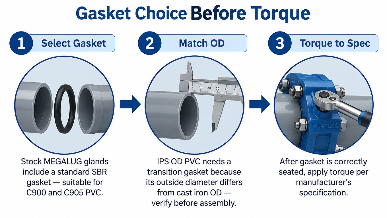
Gasket selection comes before torque. A properly torqued gland with the wrong gasket is still an incorrect assembly. Standard MEGALUG arrangements use a standard SBR gasket for compatible C900 and C905 PVC applications, while IPS OD PVC requires a transition gasket because its outside diameter differs from the cast-iron-equivalent dimension.
Assemble the joint in the right order
Clean the socket: Remove soil, debris, old gasket material, and anything that can prevent the gasket from seating.
Choose the gasket: Use the standard gasket for the listed compatible PVC dimension. Use the transition gasket for IPS plastic pipe where the instructions require it.
Seat the gasket: Place it evenly in the bell recess. A twisted or partially seated gasket can create leakage or interfere with insertion.
Insert the spigot: Bring the pipe into the bell to the required insertion mark or assembly position.
Position the gland: Slide the gland over the pipe and align it with the mechanical-joint flange.
Start the bolts: Hand-start the T-bolts and ensure the hardware engages without cross-threading.
Torque in a star pattern: Tighten progressively and evenly so the gland seats uniformly around the pipe.
For the large 42-inch and 48-inch installations, the published torque range is 120 to 150 ft-lbs (PVC MEGALUG installation data). Smaller sizes use lower torque values specified by the applicable product data. Use a calibrated torque wrench and follow the manufacturer's sequence rather than applying the large-diameter value across the entire range.
Field caution: Never treat an IPS gland, cast-iron-dimension bell, and standard gasket as interchangeable parts. The joint has to be specified as a complete assembly.
The most common failure is skipping the transition gasket on IPS PVC. Another is mixing an IPS restraint with a bell intended for a different OD basis. The joint might hold during an initial pressure check, yet still lack the intended behavior under deflection or axial loading.
For project hardware and related requirements, procurement teams can also review ATEK's fasteners and hardware category. The restraint itself must still be selected and installed from the applicable MEGALUG documentation.
Thrust Restraint Versus Thrust Blocks
A thrust block and a mechanical restraint solve the same broad problem, but they rely on different mechanisms. A concrete thrust block transfers fitting thrust into the surrounding soil through a bearing face. Its performance depends on the block geometry, concrete placement, soil bearing conditions, and available excavation space.
A MEGALUG transfers axial force through the gland, wedges, pipe wall, bolts, and mechanical-joint bell. The manufacturer's documentation describes restraint performance testing to ASTM F1674, use with AWWA C600 and AWWA D2774, FM approval for applicable fire-protection service, and full-deflection capability (EBAA Iron Series 2000PV documentation).
Factor
MEGALUG Restraint
Thrust Block
Load path
Gland and joint hardware transfer axial force through the pipe system
Concrete transfers force into surrounding soil
Soil dependence
Less dependent on a concrete bearing face
Strongly dependent on soil bearing and block placement
Excavation
Can suit congested alignments and constrained tie-ins
May require room for block excavation and placement
A block doesn't itself create a restrained, deflectable joint
Design responsibility
Must match pipe, bell, gasket, and restraint
Must match fitting thrust, soil, and block design
This isn't an argument that thrust blocks are always wrong. They remain a valid design method where soil conditions, geometry, access, and project specifications support them. The practical advantage of active restraint appears when a project has unstable or disturbed soil, limited easement width, a casing, or a retrofit tie-in that would require disruptive over-excavation.
For new PVC mains, the decision should come from the engineer's restraint design and the manufacturer's compatible product data. For difficult tie-ins, mechanical restraint often gives the crew a more controllable installation than trying to create a reliable concrete bearing surface in a crowded excavation. Teams handling larger infrastructure scopes can also use design-build engineering services for infrastructure when the procurement package needs technical coordination.
Compatibility Nuances by Pipe Class and Diameter
Pipe class and DR affect wall thickness, pressure capability, and how the gasket and gripping components interact with the spigot. A restraint selected by nominal size alone can miss those details. For C900, common DR designations include DR14, DR18, and DR25. C905 documentation can include DR14, DR18, DR21, DR25, DR32.5, and DR41. The applicable MEGALUG body and installation instructions still need to be checked against the actual pipe and joint.
PVC Class
DR Ratio
Size Range (in)
Matching Series 2000PV
Service Note
C900
DR14, DR18, DR25
4 to 12
Smaller Series 2000PV selection
Confirm C900 OD and pressure-pipe application
C905
DR14, DR18, DR21, DR25, DR32.5, DR41
14 to 48
Mid-range Series 2000PV or large-diameter Mega Series
Confirm the C905 size and joint dimensions
IPS OD PVC
Project-specific DR or dimension
Commonly 4 to 12
IPS-compatible Series 2000PV selection
Transition gasket required where specified
PVC appurtenance connection
Matching listed pipe dimension
Project-specific
Restraint selected for the connection
Confirm whether the joint is under continuous pressure service
Wall thickness changes the fit, not the basic selection logic
A thinner-wall pipe can present a different seating condition than a thicker-wall pipe of the same nominal size. The gland must fully seat, the wedges must engage without damaging the pipe, and the gasket must remain correctly positioned. Don't compensate for an uncertain fit by increasing torque. Excessive or uneven tightening can damage the assembly rather than improve restraint.
Pressure service deserves the most conservative review because the joint sees operating pressure, transient loads, and axial thrust over its service life. Appurtenance-only restraint may have a different role, but it still requires a compatible listed configuration. The product isn't automatically suitable for every fitting, repair, or transition.
The same selection discipline applies at the upper end. The standard Series 2000PV range ends at 36 inches, while larger installations extend to 42 inches and 48 inches through the Mega Series product family (PVC MEGALUG specifications). That change in diameter brings heavier hardware, different torque requirements, and a greater need for planned access around the joint.
What Mega Lugs Are Not Used For
MEGALUG isn't an electrical PVC conduit fitting. It isn't a cable-tray support, a conduit body, a sweep, or a cement-welded coupling. It also isn't a repair coupling for cracked pipe, and it shouldn't be applied to an HDPE fusion joint without a specifically engineered transition.
Some buyers search for EB-35 or DB-120 duct-bank categories while using “mega lug” as a broad term for PVC infrastructure hardware. That search path can lead to the wrong catalog entirely. Electrical conduit systems need fittings designed for conduit dimensions, pull access, bonding or grounding requirements where applicable, and the installation method specified for that raceway system.
A mechanical-joint restraint on a pressure pipe doesn't become conduit hardware because both products involve PVC.
If the job involves wire pulling, conduit bodies, sweeps, threaded adapters, cement-welded couplings, or duct-bank assembly, source from an electrical PVC conduit catalog. Don't attempt to route cable through a pressure-pipe restraint or treat the gland as a code-recognized conduit connection. The words “PVC” and “lug” overlap in search results, but the engineering functions don't.
Quick Reference Card for Selection and Torque
Use this card as a procurement checkpoint, not as a substitute for the manufacturer's installation sheet or the project engineer's approved submittal.
Series
Size (in)
PVC Standard
Gasket
Torque (ft-lbs)
Series 2000PV
3 to 12
C900 or compatible IPS OD PVC
Standard gasket for listed C900 applications, transition gasket for IPS where specified
Use the published value for the selected size
Series 2000PV
14 to 36
C905
Standard gasket for the listed application
Use the published value for the selected size
Mega Series
42 to 48
Large-diameter C905
Gasket specified for the listed assembly
120 to 150, per published PVC data
Before placing the order, confirm the nominal size, pipe standard, outside diameter, bell type, gasket, and bolt hardware. For IPS plastic pipe, verify the transition gasket requirement. For large-diameter installations, plan access for the heavier hardware and use the specified torque range.
Torque values assume a clean, properly seated assembly. A torque wrench can't correct a twisted gasket, contaminated socket, damaged spigot, or mismatched gland.
Frequently Asked Questions About MEGALUG on PVC
Does full deflection mean the joint can move freely? No. It means the listed restrained assembly is designed to accommodate the manufacturer's published deflection without joint separation when installed correctly.
When does IPS PVC need a transition gasket? IPS OD PVC requires the transition gasket where the manufacturer's instructions identify the outside-diameter difference from the cast-iron-equivalent joint dimension.
Are MEGALUG restraints useful for retrofit tie-ins? They can be practical where a thrust block would require excessive excavation, provided the pipe, bell, gasket, and service conditions are compatible.
What documentation should procurement request? Request the applicable submittal sheet, installation instructions, restraint-performance documentation, FM approval information where relevant, and AWWA installation references.
ATEK Distribution can help source compatible PVC conduit fittings, fasteners, hardware, and project documentation when your scope includes both electrical and infrastructure work. Confirm the pipe standard and restraint requirements first, then visit ATEK Distribution to request product sourcing or technical procurement support.