Flexible Metal Conduit 1 Inch

The crew has set a motor on its housekeeping pad, the feeder is already stubbed in, and someone needs a flexible connection between the box and the terminal enclosure. The material request says “1-inch flex,” but that shorthand leaves several decisions unresolved. Is the connection dry and indoors, or exposed to water and oil? Will the whip stay within the permitted bonding length? Can the conductors make the turn without forcing the conduit below its bend limit?

Those questions determine whether standard flexible metal conduit, liquidtight flexible metal conduit, or a larger raceway belongs on the purchase order. The trade size alone doesn't guarantee a workable installation. A fitting that doesn't match the conduit, a crowded terminal compartment, or a tight bend can turn a routine equipment connection into damaged insulation, rework, and an inspection problem.

Table of Contents


Understanding 1-Inch Flexible Metal Conduit Applications

A typical installation uses 1-inch flexible metal conduit as the final connection to a motor, transformer, disconnect, rooftop unit, or piece of industrial machinery. Rigid raceway brings the circuit close to the equipment, then the flexible section absorbs vibration and handles the small alignment differences that occur between the equipment and the stub-up.

That role matters. A machine may shift slightly during setup, a motor may transmit continuous vibration, and an equipment pad may not line up perfectly with the conduit stub. Standard FMC gives the installer room to make that connection without forcing rigid conduit into an awkward offset. The conduit also makes future equipment service more practical, because technicians can disconnect or reposition the unit without cutting apart a rigid run.

Why the trade size is useful

A 1-inch flexible metal conduit installation occupies less space than a larger whip while still providing useful conductor capacity for equipment connections. Product references show an inside diameter near 1.00 to 1.04 inches and an outside diameter around 1.30 to 1.38 inches, depending on construction, as documented in Southwire's flexible metal conduit data.

That makes 1-inch FMC a practical middle ground. It can route through a crowded mechanical room more easily than a larger trade size, but it isn't a miniature raceway. The installer still has to coordinate hubs, fittings, enclosure entries, conductor size, bend space, and support.

Field rule: Treat a 1-inch whip as an engineered equipment connection, not as leftover flexible raceway that can be bent into whatever space remains.

Where installations go wrong

The common failure isn't always a wrong conductor count. It's often a conduit that leaves the box at an aggressive angle, runs directly into a motor connection box, or is pulled tight enough to transfer vibration into the termination. The interlocked profile can deform when installers force a sharp turn, and the resulting restriction makes conductor pulling harder and increases the chance of insulation damage.

Support also matters. FMC needs to be secured and terminated in a way that keeps its weight and movement from loading the box or equipment fitting. A long unsupported whip may function electrically while still creating a mechanical problem. If the connection needs a longer path, more protection, or a grounding arrangement beyond the permitted conditions, a different raceway strategy may be more appropriate.

Categories of Flexible Metal Raceways

The first procurement decision is environmental. Standard FMC and LFMC may share a 1-inch trade size, but they serve different installation conditions. FMC is the interlocked metal raceway used under NEC Article 348 and governed by UL 1, while LFMC is the jacketed liquidtight product covered by NEC Article 350 and UL 360. The applicable requirements are summarized in the manufacturers' FMC and LFMC product references.
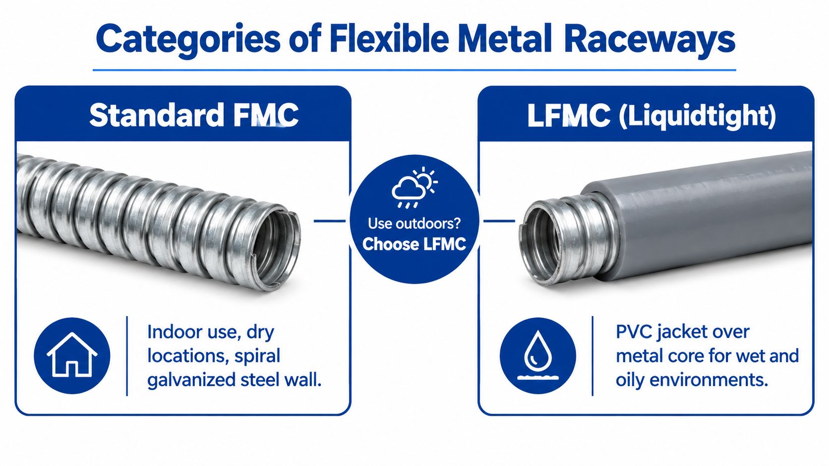
A comparison guide showing standard flexible metal conduit for dry indoor areas versus liquidtight conduit for outdoors.

Standard FMC for dry locations

Standard FMC has a spiral interlocked metal construction without the continuous outer jacket used on liquidtight products. It's a sensible choice for dry indoor equipment connections where the raceway doesn't face washdown, standing water, outdoor exposure, or conditions that can introduce liquids into the wiring method.

It works well around indoor motors, control cabinets, dry mechanical rooms, and equipment that needs vibration isolation. It's also generally easier to inspect visually because the metal profile remains exposed. That simplicity doesn't remove the need for listed fittings, proper support, or correct bonding.

LFMC for wet and exposed equipment

LFMC adds a nonmetallic outer jacket over the metal core. The jacket helps provide a liquidtight wiring method for machinery, HVAC equipment, outdoor gear, and locations exposed to water or oil. A representative 1-inch LFMC specification lists an inner diameter of about 1.041 to 1.066 inches, an outer diameter of about 1.290 to 1.315 inches, and an 8-inch minimum bend radius, with compliance references including UL 360 and NEC Article 350 in Southwire's LFMC specification.

Ordering standard FMC for an outdoor HVAC unit is a predictable mistake. The metal conduit may be physically flexible, but it doesn't provide the same liquidtight protection. Conversely, using LFMC in every indoor connection can add cost, increase outside handling dimensions, and require fittings that don't match the standard FMC system.

For broader raceway comparisons, the distinctions discussed in this EMT versus rigid conduit guide help place flexible raceways in the larger installation plan. Choose the construction based on the environment first, then verify the fitting system, listing, and enclosure requirements.

Physical Specifications and Bend Radius Limits

A one-inch whip can fail before the pull starts. The trade size identifies the raceway category, not its exact outside profile. That difference affects knockout selection, enclosure hubs, sleeve clearance, prefab dimensions, and terminal-compartment space. Confirm the approved manufacturer's submittal before releasing fittings or cutting assemblies.


1-Inch Conduit Dimensional Comparison

Conduit Type Inner Diameter Outer Diameter Min Bend Radius Weight per 100 ft
Standard 1-inch FMC About 1.000 to 1.040 inches About 1.300 to 1.380 inches 8 inches About 32 lb/100 ft
1-inch LFMC About 1.041 to 1.066 inches About 1.290 to 1.315 inches 8 inches Around 60 lb/100 ft for some constructions

The dimensional and weight values above come from Southwire's representative 1-inch FMC specification and its representative 1-inch LFMC data. Treat them as planning values. Construction, jacket, and manufacturer can change the finished envelope, so the approved product data controls procurement and fabrication.

Bend radius is a routing requirement

The 8-inch minimum bend radius is the smallest radius permitted by the manufacturer, not a target for forcing the raceway around an obstruction. A sharper turn can distort the interlocked armor, raise pulling friction, and restrict conductors inside the bend. The problem may remain hidden after the whip is installed.

Lay out the route before cutting. Account for the fitting body, enclosure entry, conductor exit, and the bend needed to reach the terminals. A short connection may still require more room than the centerline drawing shows, particularly where several conductors enter a crowded motor or equipment box.

That routing check often determines whether one-inch FMC is practical. If the bend cannot maintain its radius without crowding the termination, use a longer offset, change the equipment entry, or step up to a larger trade size. If water or oil exposure also governs the connection, evaluate LFMC rather than forcing standard FMC into a location it does not suit.

Coordinate the real envelope

BIM coordination should show more than the raceway centerline. Include the actual outside diameter, fitting, locknut or hub, and the clearance needed to install and tighten the connection. LFMC also requires room for its jacket and sealing components, even where its listed outside dimensions differ from standard FMC.

Prefab check: Verify outside diameter and bend radius from the selected manufacturer before building a batch of whips. A trade-size label alone is insufficient for fabrication.

Fittings and Termination Methods

A flexible raceway performs only as well as its terminations. The fitting has to match the conduit type, enclosure entry, location rating, and bonding method. A standard FMC connector isn't a substitute for an LFMC liquidtight connector, and a fitting that grips the wrong portion of the conduit can fail the mechanical connection even when the raceway itself is listed.
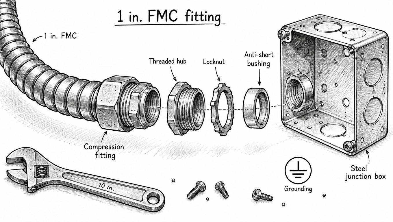
Exploded view diagram showing components for installing a 1 inch flexible metal conduit fitting into a junction box.

For standard FMC, select a connector designed for the specific conduit construction and the enclosure entry. The connector must seat the conduit fully, engage the interlocked armor as intended, and provide a secure connection to the box or equipment. Verify the knockout or threaded opening rather than assuming every 1-inch entry uses the same physical geometry.

Choosing the termination

Set-screw-style fittings can be efficient in suitable indoor applications, particularly where the connection is accessible and the fitting is listed for the FMC construction. Compression fittings use a mechanical compression action that can provide a firm connection and are often useful where a more controlled grip is preferred. The correct choice depends on the listing, enclosure, location, and project specification, not just installer habit.

For LFMC, use a listed liquidtight fitting made for the jacketed conduit. The fitting's sealing components must engage the jacket correctly, while the internal metal core must remain bonded through the fitting system. A loose seal can admit moisture, and an improperly seated core can compromise both mechanical security and electrical continuity.

The broader selection of flexible conduit fittings includes connectors, couplings, elbows, adapters, reducers, bushings, and locknuts. Match each component to the raceway and termination rather than mixing parts from unrelated systems.

A practical installation sequence

  1. Prepare the cut. Make a clean, square cut with the approved tool. Remove sharp metal that could damage conductors or prevent the fitting from seating.
  2. Install the connector components. Follow the fitting manufacturer's order for locknuts, bushings, sealing rings, grounding cones, and compression parts.
  3. Seat the conduit fully. Don't stop when the conduit merely touches the fitting. The metal core or armor must engage the connector as designed.
  4. Tighten and inspect. Check the fitting for movement, verify the locknut or hub is secure, and perform the physical tug check required by the installation practice.
  5. Protect the conductors. Confirm that no sharp edge, exposed armor, or displaced sealing component can contact the insulation.

A short visual demonstration can help crews understand how the fitting components stack and lock together.

The fitting should remain accessible during inspection and service. Burying a questionable termination behind equipment makes a small installation error expensive to correct.


Conduit Fill and Real-World Pullability

A fill table answers only one question: whether the conductor area is within the permitted raceway capacity. It doesn't tell you whether the crew can pull the conductors through a corrugated metal interior, around a tight equipment offset, and into a crowded terminal box without damaging insulation.

For 1-inch FMC, an NEC-based fill table lists capacity of 33 one 14 AWG conductors, 24 of 12 AWG, 15 of 10 AWG, and 9 of 8 AWG in the applicable table entries at Elliott Electric's conduit fill reference. Those figures are useful for code calculation, but they're not a recommendation to load every whip to the mathematical limit.
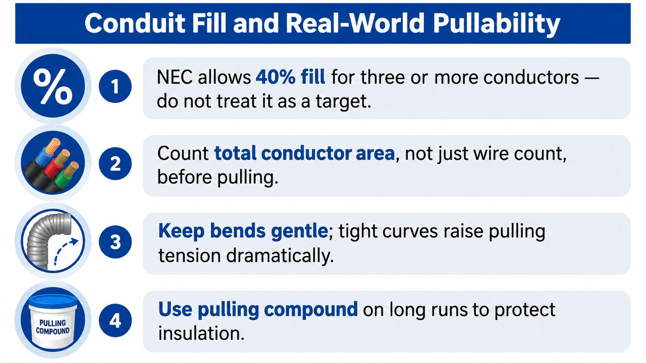
An infographic detailing four professional tips for conduit fill and easier cable pulling during electrical installations.


Why the table and the field disagree

FMC creates more friction than a smooth raceway because the conductors pass over an interlocked interior profile. Every bend adds resistance, and the final turn into a device box can be more difficult than the straight portion. Conductor insulation can scrape against the metal profile when the pull tension rises, especially if the installer yanks the bundle rather than controlling it.

The practical limit also depends on conductor diameter, insulation type, route length, number of bends, temperature, and access at both ends. A conductor count that looks harmless on paper may become a poor choice once the crew has to make a tight equipment connection and leave enough slack for termination.


Pull planning that saves rework

  • Count conductor area. Use the actual conductor dimensions from the approved wire data, not a rough assumption based only on AWG.
  • Plan the route before pulling. Keep the conduit as straight and gently curved as the equipment layout allows.
  • Protect the insulation. Use an appropriate pulling compound where the manufacturer and installation conditions allow it, and control the pull instead of exceeding the conductor's handling limits.
  • Separate crowded terminations from raceway sizing. A conductor bundle may fit the conduit yet fail to fit comfortably in the equipment box.

Estimator's judgment: If the crew needs excessive force to complete a 1-inch pull, the raceway is already too small for the job, even if the fill calculation passes.

Stepping up to a larger trade size can reduce pulling effort, conductor damage risk, and termination congestion. The decision should account for the full installed cost, including labor, damaged wire, replacement fittings, and the delay caused by a failed pull. For cable and conductor selection, keep the actual wire construction aligned with the raceway plan, using a supplier that can verify dimensions and compatibility through its wire and cable offerings.

Bonding and Grounding Requirements

FMC can serve as a bonding path in permitted installations, but that permission has conditions. NEMA guidance identifies FMC bonding under the applicable requirements of NEC Articles 348 and 250, including a 6-foot bonding-length limit, as described in the NEMA FMC guidance document.

That limit changes the procurement question. If a 1-inch FMC connection exceeds the allowed length, the installer needs a separate equipment grounding conductor. The same decision may apply when the environment, equipment, or circuit conditions make reliance on the flexible metal wall unsuitable.


Don't confuse continuity with durability

A meter can show continuity during commissioning while the long-term grounding path remains vulnerable. Corrosion at joints can increase resistance over time, and repeated vibration can affect mechanical interfaces. Damp, outdoor, washdown, or corrosive facilities deserve a more conservative specification, particularly where maintenance access is poor.

A separate equipment grounding conductor gives the fault-current path an independent route through the flexible connection. It doesn't eliminate the need to bond the raceway correctly, but it reduces dependence on the interlocked metal profile and its terminations.
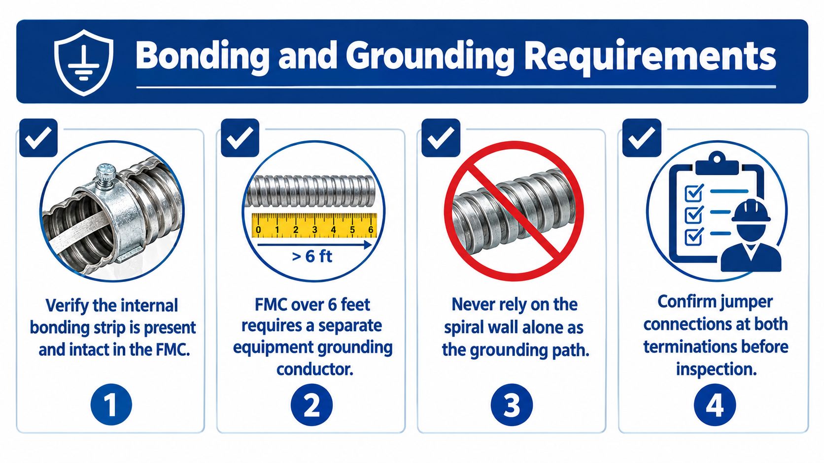
A safety infographic detailing four key bonding and grounding requirements for installing flexible metal conduit systems.


Check both ends

Inspectors and commissioning teams should be able to verify the bonding path at the box and at the equipment. Confirm that the fitting is listed for the raceway, that the connection is mechanically secure, and that any required bonding jumper or internal grounding conductor is continuous between terminations.

Use a dedicated grounding conductor when the connection length, installation environment, equipment design, or governing electrical requirements call for it. Don't make the field electrician infer that requirement from a vague material description such as “1-inch flex.” Put the raceway type, fitting type, length, and grounding method on the submittal or material schedule.

Cross-References to Related Raceways

1-inch FMC solves a specific problem. It provides a flexible, metal connection between fixed infrastructure and equipment that moves, vibrates, settles, or needs service access. It isn't automatically the right replacement for EMT or rigid metal conduit on a long exposed run.

Decision matrix for common choices

Raceway Best use Strength Limitation
1-inch FMC Final equipment connections in suitable locations Handles vibration and alignment changes Limited by bend radius, support, bonding conditions, and pullability
EMT Long, straight indoor runs Efficient for organized routing and broad infrastructure paths Doesn't accommodate equipment movement or terminal misalignment well
RMC Areas requiring stronger physical protection Robust protection for severe exposure Heavier, slower to install, and less practical for routine flexible connections

EMT usually earns its place on straight ceiling routes, wall runs, and organized distribution paths. It provides a clean, rigid pathway, but it becomes awkward at motor terminals and vibrating equipment. Trying to force EMT into the last connection often produces offsets that consume space and make service more difficult.

RMC belongs where physical damage is a serious concern or where the project specification requires a heavy-duty metallic raceway. Its strength is valuable in exposed industrial areas, loading zones, and other locations where a lighter raceway may not provide enough protection. Its weight and installation effort make it a poor default for every equipment whip.

Build a hybrid system

Many good installations use more than one raceway type. EMT carries the fixed run, a box or disconnect provides the transition, and FMC or LFMC handles the final equipment connection. That arrangement puts each wiring method where it performs best instead of making one product solve every condition.

For outdoor equipment, the flexible portion needs the environmental protection of LFMC and fittings designed for that product. For dry indoor machinery, standard FMC may be adequate, provided the bend, support, termination, fill, and bonding requirements are satisfied.

The right question isn't “Which raceway is cheapest per foot?” It's “Which combination gives the crew a secure, serviceable, inspectable path with the fewest avoidable transitions?” Material price matters, but so do fitting labor, pulling time, equipment access, and the cost of reopening a completed connection.

Quick Reference and Procurement Checklist

When a purchase request says 1-inch flexible metal conduit, stop and clarify the installation before releasing material. A complete order identifies the raceway, environment, fittings, grounding method, and conductor plan.

Confirm the raceway

  • Choose the construction: Specify standard FMC for the intended dry-location application, or LFMC where the wiring method must resist liquid exposure.
  • Verify the listing: Match standard FMC to the applicable UL and NEC requirements, and confirm LFMC documentation includes its required liquidtight listing.
  • Check the dimensions: Use the manufacturer's inner and outer diameters for enclosure entries, hubs, sleeves, and BIM coordination.
  • Record the bend requirement: Preserve the manufacturer's minimum bend radius in the layout and prefab drawing.


Confirm the fittings

  • Match the connector: Use fittings listed for the exact FMC or LFMC construction.
  • Coordinate the entry: Verify knockout, hub, locknut, bushing, and enclosure compatibility before shipment.
  • Specify the sealing parts: LFMC installations need the fitting components that maintain the liquidtight rating.
  • Plan service access: Don't place a termination where the crew can't inspect or retighten it.


Confirm the conductors and bonding

  • Calculate actual fill: Use conductor area and the applicable fill table. Don't treat the listed maximum as the preferred field load.
  • Review the pull route: Account for bends, friction, conductor insulation, and terminal-box space.
  • Check the length: Determine whether the FMC connection stays within the permitted bonding conditions.
  • Add the grounding conductor when required: Include it in the material list rather than expecting the installer to improvise in the field.

A strong submittal should show the manufacturer, product family, trade size, listing, dimensions, bend radius, fitting series, environmental rating, and grounding arrangement. That level of detail prevents the warehouse from sending standard FMC when the crew needs LFMC, or sending a conduit that fits the label but not the equipment entry.

For project teams, the most reliable workflow is to confirm the route and termination first, then select the raceway and conductor package. That sequence avoids the common trap of choosing 1-inch flex because it appears on the plan, only to discover that the actual equipment connection needs more room or a different environmental rating.


ATEK Distribution can help contractors and project teams source 1-inch FMC, LFMC, compatible fittings, wire, and related raceway materials while reviewing specifications and compliance documentation. Visit ATEK Distribution to submit your requirements and coordinate sourcing for equipment connections that need the right product, fitting, and grounding approach.
2 Conduit PVC Sizing and Installation Guide

A conductor package arrives at the warehouse, and the purchase order says only “2-inch PVC conduit.” The field team assumes the raceway has a 2-inch bore, the estimator checks a familiar fill table, and the problem appears later when the actual product has a smaller usable interior or the pull becomes unmanageable around several bends.

That mistake starts with the label. 2-inch PVC conduit is a nominal trade size, not a promise of a 2-inch inside diameter. Schedule, wall thickness, product type, conductor insulation, bend geometry, and installation environment all affect whether the selected raceway will fit the conductors and remain practical to install. The following guide addresses both code-based sizing and the physical realities that can create damaged insulation, failed inspections, and procurement delays.

Table of Contents


Understanding 2-Inch PVC Conduit Basics

A trade size identifies a standardized product category. It doesn't necessarily describe the exact dimension available to conductors. In North American PVC piping, 2-inch nominal conduit has a 2.375-inch outside diameter, while the inside diameter changes with wall thickness and schedule. Published dimensional references list about 2.047 inches inside diameter for Schedule 40 and about 1.881 inches for Schedule 80, a difference of roughly 8% in usable inside diameter between the two variants (published PVC size dimensions).

That distinction matters at three points in a project:

  • Estimating: A conduit allowance based only on the trade-size label can overstate usable space.
  • Engineering: Conductor fill must use the actual raceway interior and the applicable conductor areas.
  • Installation: A compliant fill calculation doesn't automatically guarantee an easy pull through a long run with bends.

A procurement description such as “2-inch PVC” is incomplete. The material request should identify the electrical raceway listing, schedule, product series, intended environment, and fitting compatibility. Electrical conduit isn't interchangeable with plumbing pipe just because both products use terms such as Schedule 40 or Schedule 80.

Why the outside diameter stays relevant

The common outside diameter lets manufacturers produce compatible fittings for the nominal raceway family. The interior is where the procurement risk appears, because thicker walls consume usable bore while preserving the same nominal outside dimension.

This is why a purchase order, submittal, or BOM should carry the exact product designation rather than relying on a warehouse shorthand. A project team reviewing conduit and raceway as core electrical infrastructure should verify the product data before approving substitutions.

Practical rule: Size the raceway from the actual inside diameter and conductor data, then confirm that the selected product and fittings match the specification.

Categories of 2-Inch PVC Raceways

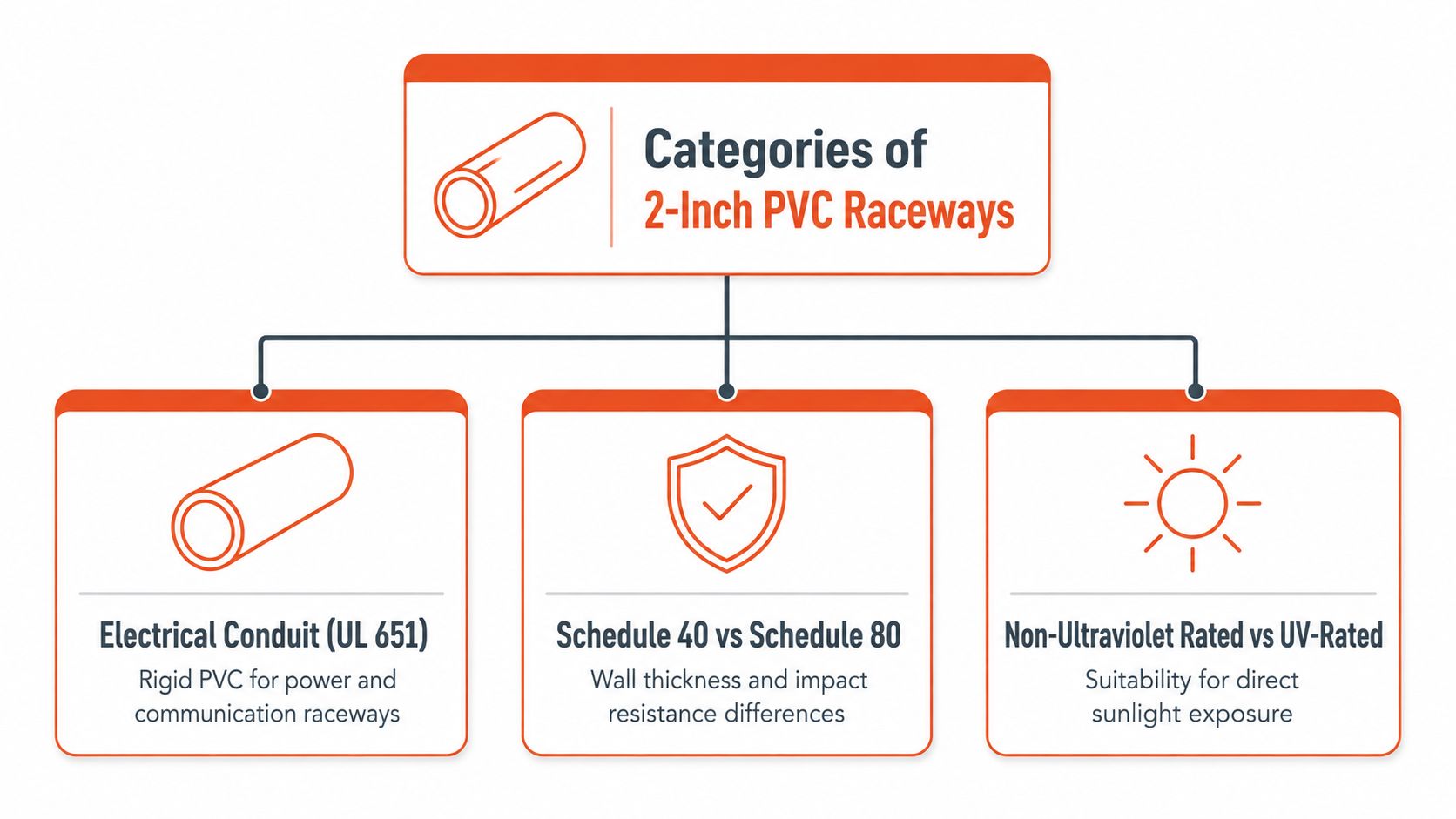
The phrase “2-inch PVC” covers more than one raceway family. A rigid electrical conduit, a PVC-coated metal raceway, and flexible ENT may share a nominal size reference while differing in construction, listing, installation method, and physical behavior.

A diagram outlining the categories of 2-inch PVC raceways, including standards, wall thickness, and UV ratings.

Rigid PVC conduit

Standard rigid PVC conduit is the familiar nonmetallic raceway used for underground, encased, and selected above-ground electrical installations. Schedule 40 generally prioritizes a larger usable bore within the same nominal size, while Schedule 80 uses a thicker wall for greater resistance to impact and crushing. Electrical products are commonly specified to recognized requirements including UL 651, NEMA TC-2A, and ASTM 1784, but the governing requirement must come from the project specification and applicable jurisdiction.

Schedule 40 is often a sensible choice where concrete encasement or burial provides the primary protection. Schedule 80 becomes more appropriate where the exposed portion could receive physical impact. The transition between those products should be planned in the BOM rather than improvised at the jobsite.

PVC-coated rigid steel conduit

PVC-coated rigid steel conduit combines a metallic raceway core with a corrosion-resistant exterior coating. It belongs in a different product category from all-plastic PVC conduit and may be selected for corrosive industrial environments where the project requires metallic raceway construction plus protective coating.

One published 2-inch PVC-coated rigid steel product lists a 2.46-inch outside diameter, 2.08-inch inside diameter, 0.19-inch wall thickness, and 9.91-foot length (published PVC-coated rigid steel product data). Those dimensions show why the phrase “2-inch conduit” alone can't support a reliable fill or clearance decision.

Flexible nonmetallic raceway

ENT provides flexibility where routing around equipment, structural details, or short connections makes rigid raceway inconvenient. A published 2-inch Carlon ENT product lists a 2.030-inch nominal inner diameter and 2.375-inch outer diameter (published ENT product dimensions). Its installation requirements and permitted applications must be checked separately from those for rigid PVC.

Comparing Schedule 40 and Schedule 80 Dimensions

Schedule 40 and Schedule 80 share the same nominal trade size and commonly share the 2.375-inch outside diameter, but their wall geometry is materially different. For a 2-inch Schedule 80 product, published manufacturer data lists an inside diameter of about 1.881 inches and a wall thickness of 0.218 inch. Schedule 40 has the thinner wall and therefore the larger usable bore (Wheatland PVC conduit specification data).

Attribute Schedule 40 PVC Schedule 80 PVC
Nominal trade size 2 inch 2 inch
Outside diameter 2.375 inches 2.375 inches
Inside diameter About 2.047 inches About 1.881 inches
Wall thickness Thinner than Schedule 80 0.218 inch
Usable conductor space Larger bore Smaller bore
Typical selection logic Burial or encasement where protection is provided Exposed areas requiring greater impact resistance

The choice is therefore not just “light duty versus heavy duty.” It is a balance between mechanical protection and conductor capacity. Schedule 80 can be the correct specification for an exposed plant-floor riser or another location vulnerable to impact, but its thicker wall reduces the space available for conductors. Using it throughout a run where the environment doesn't require that protection can make the pull harder without solving a real design problem.

Mechanical strength versus working space

Published product information commonly shows around 1,400 pounds of crush strength for both 2-inch Schedule 40 and Schedule 80 variants (PVC electrical conduit market and product context). That benchmark shouldn't replace the manufacturer's current data sheet, but it reinforces an important point: selection involves more than a simple strength ranking.

A project may need Schedule 80 at an exposed transition and Schedule 40 in a protected underground segment. That arrangement preserves a larger bore where it helps installation while reserving the thicker product for the area exposed to damage. Confirm the transition fittings, solvent-welding requirements, and local inspection expectations before releasing the material.

The most expensive conduit error is often not the price difference between schedules. It's discovering after delivery that the selected schedule won't accommodate the planned conductor set or route.

Navigating NEC Conduit Fill and Pulling Tension

NEC Chapter 9 conduit fill rules establish the maximum portion of the raceway interior that conductors may occupy. For one conductor, the limit is 53%; for two conductors, 31%; and for more than two conductors, 40% (NEC Chapter 9 PVC fill guidance). These percentages apply to the actual inside area, not the nominal trade-size name.

A practical calculation follows this sequence:

  1. Identify the exact conduit series and inside diameter.
  2. Determine the cross-sectional area of every conductor, including equipment grounding conductors where installed.
  3. Add the conductor areas.
  4. Compare the result with the applicable fill limit.
  5. Review ampacity, bend geometry, pulling length, and termination space separately.

The fill table answers “does the conductor area fit?” It doesn't fully answer “can the crew pull the conductors without damaging them?”

Why a compliant pull can still fail in practice

Friction rises when conductors press against each other and the raceway wall. Long straight runs, multiple bends, tight sweeps, and changes in elevation can turn a mathematically acceptable installation into a difficult field operation. Schedule 80's smaller bore adds another constraint, even though the nominal size remains 2 inch.

A run near the 40% maximum may pass the fill calculation yet require excessive pulling force or create unacceptable stress at bends. The installation team should evaluate whether upsizing the raceway, dividing the circuit into multiple raceways, revising the route, or adding an accessible pull point will reduce risk. Moving to 2.5-inch or 3-inch conduit can be a practical design decision when the conductor package and route make a 2-inch pull marginal, but the final selection belongs to the engineer and applicable code requirements.

Use the exact conductor insulation type and manufacturer's dimensions when verifying a THHN or THWN package. A PVC conduit fill reference can support the review, but it shouldn't be treated as permission to ignore the selected product's data sheet or the authority having jurisdiction.

A 90-degree change also needs more than a nominal angle on the drawing. The bend radius, total route geometry, and access for pulling all affect installation effort. Use the project-specific fitting and route details when selecting a 90-degree conduit elbow, and don't finalize the raceway solely from a conductor-count lookup.

Essential Fittings and Installation Components

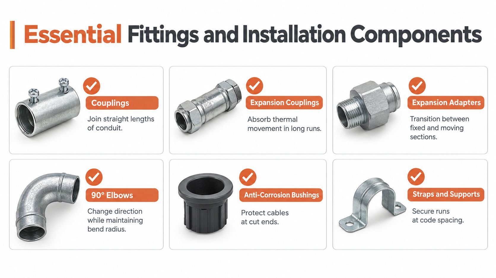
Straight conduit sticks rarely represent the complete material requirement. A missing coupling, transition adapter, or expansion fitting can stop a crew even when the primary raceway has already arrived.A visual guide showing various essential conduit fittings and installation components like couplings, elbows, and straps.


Build the fitting package with the conduit

Couplings join straight lengths and must match the conduit system. Don't mix fitting dimensions casually between product families, particularly when the specification requires a particular schedule or listing.

Sweep bends are generally preferable to sharp directional changes where the route permits. They provide a more manageable path for conductors, while a compact elbow may suit a constrained connection. The correct choice depends on the conductor size, pulling method, enclosure entry, and available space.

Expansion fittings accommodate movement on exposed outdoor runs and at transitions between sections with different restraint conditions. Include the required expansion couplings or adapters in the original BOM, rather than assuming they can be added after the raceway is installed.

Protect the cable at transitions

PVC raceway often connects to metallic boxes, cabinets, panel enclosures, or equipment. That transition may require adapters, bushings, locknuts, grounding or bonding components where applicable, and protection at cut ends. The fitting must suit both the raceway material and the enclosure entry.

A practical BOM review should identify:

  • Straight joints: Couplings and solvent-compatible joining materials.
  • Direction changes: Sweep bends and elbows selected for the route.
  • Movement control: Expansion components for locations subject to thermal movement.
  • Enclosure transitions: Adapters, connectors, bushings, and locknuts.
  • Support hardware: Straps, clamps, and approved support components.
  • Spare installation items: End protection and materials needed to prevent debris from entering the raceway.

The schedule of the fitting must match the schedule of the conduit unless the product documentation specifically permits the combination. A useful PVC conduit fittings category can help organize the accessory portion of a material request, but the project specification remains the controlling document.

Installation Considerations and Burial Depths

The warehouse label becomes a field problem at the trench. A crew can install the correct nominal raceway and still fail inspection if it measures cover from the wrong reference point or uses the wrong product at an exposed riser.

NEC Table 300.5 generally requires 18 inches of cover for PVC conduit in typical underground locations. Cover is measured from the finished grade to the top of the conduit, not to the trench bottom or the conduit centerline (PVC conduit burial-depth guidance). The required depth can change with the location, surface protection, traffic exposure, and local amendments, so the inspector and design documents should be consulted before excavation.

Plan the underground section from the top of the raceway

For a 2-inch system, the conduit outside diameter occupies space below the required cover. The trench design should account for the complete assembly, including bedding, conduit, warning or identification requirements where specified, and backfill that won't damage the raceway.

Schedule 40 may suit a protected buried section, while Schedule 80 may be required where the raceway emerges from grade or becomes exposed to physical damage. That change should be shown on the drawings and reflected in the takeoff. It shouldn't be left to the installer to discover after the trench is open.

Treat above-ground sections as a separate exposure

Above grade, the team needs to review support, UV suitability, impact exposure, enclosure entries, and the protection of conductors at every opening. A product intended for a protected location may not be appropriate for direct sunlight or a plant area where carts, tools, or equipment can strike the raceway.

Before backfilling, verify the installed route against the approved drawings and inspection requirements. Record transitions, pull points, and changes in schedule. Those records help maintenance teams later, particularly when a facility adds circuits or troubleshoots a buried feeder.

Field check: Measure cover to the top of the conduit, verify the schedule at every exposed transition, and obtain local approval before the trench disappears.

Cross-References to Alternative Raceway Systems

PVC is useful, but it isn't a universal raceway. A specification that calls for 2-inch PVC should still be challenged against the environment, equipment requirements, and grounding strategy.

EMT may be preferable for indoor exposed routing where a metallic raceway provides a compact installation and the facility's design accepts it. It requires different connectors, tools, handling practices, and bonding considerations than PVC, so a substitution affects more than the straight conduit line item.

Rigid metal conduit is a candidate where the route faces substantial physical abuse or where the engineered system requires a durable metallic raceway. It can also change labor, threading, fitting, corrosion, and support requirements. The estimator should compare the complete installed system rather than comparing the price of one length of PVC with one length of metal conduit.

Situations that justify a design review

PVC may be the wrong selection when the route is exposed to severe impact, when the project's temperature and product-rating requirements exceed the selected PVC system, or when the facility requires a continuous metallic equipment grounding path. Those conditions don't automatically dictate one replacement product, but they do require an engineering review.

Flexible metal conduit can solve a different problem, such as equipment connections where vibration or movement makes a rigid raceway impractical. It also introduces its own fitting, grounding, protection, and permitted-use requirements.

The key procurement question is not “what is the cheapest 2-inch raceway?” It is “which complete raceway system satisfies the environment, conductor route, compliance documents, and installation method?” A substitution should include the conduit, fittings, supports, transition hardware, and documentation needed for approval.

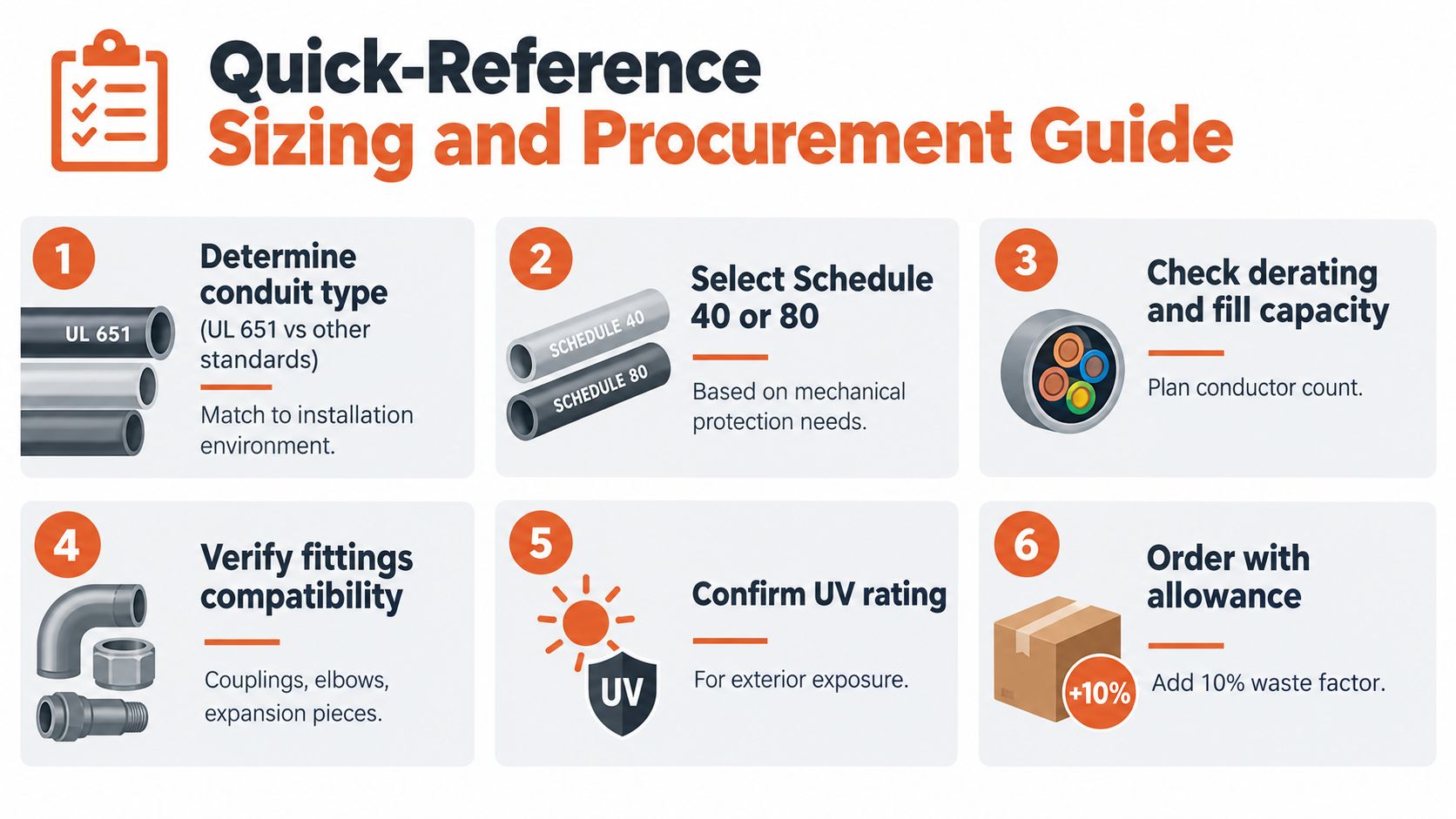
Quick-Reference Sizing and Procurement Guide

A reliable purchase package turns the nominal label into a controlled specification. Before releasing a BOM, have the estimator, engineer, and procurement lead verify the raceway against the actual route and conductor package.

A six-step quick-reference guide for sizing and procuring electrical PVC conduits for construction projects.

Review the technical selection

  • Identify the product family: Confirm whether the request is rigid electrical PVC, PVC-coated rigid steel, ENT, or another raceway type.
  • Confirm the listing and standard: Check the required UL, NEMA, ASTM, or project-specific documentation before accepting an alternative.
  • Select the schedule: Use Schedule 40 or Schedule 80 according to physical protection needs, not habit.
  • Verify usable bore: Compare the manufacturer's inside diameter with the conductor areas and applicable fill limit.
  • Review the route: Account for bends, sweeps, pull points, elevation changes, and the planned pulling method.
  • Check the environment: Confirm burial, sunlight, moisture, impact, temperature, and enclosure-transition requirements.
  • Complete the fitting BOM: Include couplings, elbows, expansion components, adapters, bushings, supports, and end protection.
  • Confirm documentation: Gather product data, submittals, compliance information, and approved-alternative records before delivery.

The infographic includes an allowance for 10% waste, but any project-specific allowance should be set by the estimator from the route, cut plan, and supplier packaging rather than applied blindly. Lead time also deserves attention. Conduit may be available while a particular elbow, expansion fitting, transition, or listed accessory is not.

Use this video as a visual supplement to the written review, not as a replacement for the project specification, current code requirements, or manufacturer instructions.

For industrial and mission-critical work, the procurement review should also identify approved alternatives before a shortage occurs. A distributor can help compare manufacturer documentation, coordinate substitutions, consolidate fittings with the conduit package, and keep a delayed accessory from holding up an otherwise complete installation.


For 2-inch PVC conduit projects, ATEK Distribution can support BOM review, product sourcing, compliance documentation, approved alternatives, and hard-to-source fittings or raceway components. Visit ATEK Distribution to request project-specific procurement assistance and keep your electrical installation moving.

Push-In Connectors vs Wire Nuts: Which Should You Use?

ComparisonWire connectorsNEC 110.14

Push-In Connectors vs Wire Nuts: Which Should You Use?

A practical comparison of push-in wire connectors and twist-on wire nuts for electricians and contractors: conductor types, code compliance, reliability, box space, labor and cost.

Short answer

Push-in connectors are faster to install and easier to inspect than wire nuts, and they are the better choice for solid copper conductors in crowded boxes. Wire nuts cost less per splice, handle a wider mix of wire sizes and stranded conductors, and remain the safer default when you are joining unlike conductors or fixture leads. Both are UL-listed splicing connectors, and both meet the NEC when you install them within their listing.

Key takeaways

  • Solid copper in a crowded box: push-in connectors are faster and more consistent.
  • Stranded wire, fixture leads or mixed sizes: use wire nuts, or lever connectors listed for stranded wire.
  • Both are tested to UL 486C. Code compliance depends on staying inside the listing (NEC 110.3(B)).
  • Connectors do not count toward box fill under NEC 314.16.
  • Aluminum needs a connector marked for aluminum. Standard push-ins and wire nuts are copper only.

This guide from ATEK Distribution compares push-in connectors and wire nuts on the points that decide a real installation: conductor type, speed, reliability, reuse, box space and cost. If you are also weighing lever connectors, see our WAGO vs wire nuts vs Ideal comparison. That article covers lever nuts. This one covers push-in connectors only.

Push-In Connectors vs Wire Nuts at a Glance

Push-in connectors vs twist-on wire nuts
FactorPush-in connectorsTwist-on wire nuts
How it grips the wireInternal spring clamp presses the conductor against a metal contact barTapered metal coil threads onto the twisted conductors
Install methodStrip to the gauge, push straight inStrip, hold conductors together, twist until tight
Solid copperYes, what they are designed forYes
Stranded wireLimited. Many models are solid-only; some accept stranded. Check the listingYes, including solid-to-stranded combinations within the listed range
Visual checkClear housings on many models show the wire seatedNo. You rely on technique and a tug test
Skill dependenceLow. Correct strip length is the main variableHigher. Pre-twist, torque and conductor alignment all matter
ReuseUsually single-use or limited reuse (per manufacturer)Generally treated as single-use once removed
Size in the boxCompact, flat, stack neatlyBulkier, especially larger sizes
Cost per spliceHigherLower
StandardUL 486C (splicing wire connectors)UL 486C (splicing wire connectors)

Swipe the table sideways to see every column.

Which Connector Should You Use? A 30-Second Decision Guide

Work down the list and stop at the first question that applies to your splice:

  1. 1. Are any conductors aluminum?
    Connector marked for aluminumNever a standard copper-only connector
  2. 2. Is it a damp, wet or underground splice?
    Sealed, gel-filled connectorListed for the location (UL 486D)
  3. 3. Will the connection be reopened often?
    Lever connectorDesigned to open and close
  4. 4. Stranded wire, fixture leads or mixed sizes?
    Twist-on wire nutWithin the combinations on the package
  5. 5. Solid copper, especially in a crowded box?
    Push-in connectorFastest, most consistent, easy to inspect

What Is a Push-In Wire Connector?

A push-in wire connector is a small splicing connector with one port per conductor. Inside each port, a spring clamp holds the stripped wire against a metal contact bar that links all the ports together. You strip the conductor to the length marked on the connector, push it in until it stops, and the connection is made. Common examples include the WAGO 2773 series and the Ideal In-Sure line.

Push-in connectors come in 2, 3, 4, 5 and 8-port versions. Because each wire has its own port, you can add or check one conductor without disturbing the others.

What Is a Wire Nut?

A wire nut, also called a twist-on wire connector, is a plastic shell with a tapered metal spring coil inside. You hold the stripped conductors side by side and twist the nut clockwise. The coil draws the conductors together and holds them under pressure. Wire nuts have been the standard splice in North American building wire for decades, and most electricians can install them quickly and reliably.

Wire nut sizes are color-coded, but the color for a given wire range is set by each manufacturer. Always read the conductor combinations printed on the packaging rather than going by color alone.

Push-In vs Wire Nuts: The Key Differences

1. Conductor type: solid vs stranded

This is the most important difference. Push-in connectors are built around solid copper conductors. A stranded wire can splay when pushed into the port, and some strands may not seat under the clamp. Some push-in models are listed for certain stranded conductors, but many are not. If the listing does not name stranded wire, do not use it on stranded wire.

Wire nuts handle stranded conductors, and they handle solid-to-stranded combinations such as a solid branch-circuit conductor joined to a stranded fixture lead, as long as the combination is on the manufacturer’s chart. For light fixtures, ceiling fans and many appliances with stranded pigtails, wire nuts or lever connectors are usually the better fit.

2. Installation speed and consistency

Push-in connectors are faster in most boxes. There is no pre-twisting and no judging how tight is tight enough. The result is also more consistent across a crew, because the spring sets the contact force rather than the installer’s hand. On large jobs with hundreds of device boxes, that consistency matters as much as the time saved.

Wire nuts take slightly longer per splice, and quality depends more on the person installing them. A well-made wire nut splice is very reliable. A rushed one, with one conductor sitting short of the others, is one of the most common causes of loose connections found during service calls.

3. Inspection and troubleshooting

Many push-in connectors have transparent housings, so you or an inspector can see that each conductor is fully seated. Some also include a test port for a meter probe. With a wire nut you cannot see inside the splice, so the check is a firm tug on each conductor after installation.

4. Reuse and removal

Neither type is designed for repeated reconnection. Some push-in connectors allow removal with a twist-and-pull motion, and the manufacturer may permit limited reuse. Others are single-use. Wire nuts can be unscrewed, but once the spring has been loaded and the conductors disturbed, the practical rule is to re-strip the conductors and use a new connector. If you expect to reopen a connection often, for example in control panels or fixture change-outs, a lever connector is the better tool.

5. Box space

Push-in connectors are smaller and flatter than most wire nuts, so crowded device boxes are easier to close. Box-fill calculations under NEC 314.16 count conductors, clamps, support fittings, devices and equipment grounding conductors, not the splicing connectors themselves. Push-ins do not change the calculated fill. They do leave more physical room for the device and folded conductors, which reduces strain on terminations. For deep and extra-capacity boxes, see our electrical boxes range.

6. Cost

Wire nuts cost less per splice. Push-in connectors cost more per unit, but can lower total installed cost on labor-heavy jobs. For a contractor, the right comparison is material plus labor per box, not material alone. ATEK can quote both in contractor quantities so you can run that comparison on your own job.

Are Push-In Connectors as Safe as Wire Nuts?

Yes, when they are used within their listing. Both push-in connectors and twist-on wire nuts are tested to UL 486C, the standard for splicing wire connectors. Problems with either type almost always come from use outside the listing, such as stranded wire in a solid-only push-in, the wrong strip length, conductor combinations not on the chart, or aluminum conductors in a copper-only connector.

The NEC requirements that apply are the same for both:

  • NEC 110.3(B): install listed equipment according to its listing and instructions, which includes the wire range and conductor type printed on the packaging.
  • NEC 110.14: terminations and splices must be identified for the conductor material, and conductors of dissimilar metals must not be mixed unless the connector is identified for it.
  • NEC 300.14: leave enough free conductor at each box (generally at least 6 inches) for splicing and future work.

Code sections are cited from the NEC as published. Confirm the edition your jurisdiction enforces. Minnesota adopted the 2026 NEC on August 17, 2026; see our Minnesota 2026 NEC changes summary.

Push-In Connectors vs Backstab Receptacles: Not the Same Thing

Many people searching “push-in vs wire nuts” are really thinking about backstabbed receptacles, where the conductor is pushed into a hole in the back of an outlet. That is a device terminal, not a splicing connector. Backstab terminals on many receptacles accept only 14 AWG solid copper, and many electricians prefer the side screw terminals or back-wire clamp terminals for better contact. Standalone push-in connectors are a different product, listed to a different standard, and should not be judged by backstab experience.

When to Use Push-In Connectors vs Wire Nuts

Choose push-in connectors for

Solid copper, speed and inspection

  • Solid copper branch-circuit splices in new construction and remodels
  • Pigtailing devices in crowded boxes
  • Large residential or commercial jobs where speed and crew consistency reduce labor cost
  • Work where an inspector or client values a visible, checkable connection

Choose wire nuts for

Stranded leads, mixed sizes and budget

  • Stranded conductors, and solid-to-stranded splices within the listed combinations
  • Light fixtures, fans and appliances with stranded leads
  • Mixed wire sizes outside a push-in connector’s range
  • Budget-driven work where material cost per splice matters most

For connections you may need to reopen, or for fine-stranded control wiring, choose a lever connector instead. Our guide Are WAGO connectors code approved? explains the listing and code questions for lever types.

Special Cases: Aluminum, Grounding and Wet Locations

Aluminum wire

Standard push-in connectors and standard wire nuts are for copper conductors only. Splicing aluminum branch-circuit wiring, or joining aluminum to copper, requires a connector specifically identified for that use and marked for aluminum, such as an AL/CU-rated twist-on connector or a purpose-built aluminum-to-copper pigtail connector. Check the marking before you buy. Using a copper-only connector on aluminum is a known fire risk, and the U.S. Consumer Product Safety Commission publishes guidance on repairing aluminum branch-circuit wiring.

Equipment grounding conductors

Green twist-on connectors, often with a hole in the tip for a pigtail, are made for splicing equipment grounding conductors. Push-in connectors can also join grounding conductors when the listing allows. Either way, the grounding splice must stay continuous if a device is removed, which is why grounds are pigtailed rather than daisy-chained through device terminals.

Damp, wet and underground splices

Neither a standard push-in connector nor a standard wire nut is made for wet locations or direct burial. Outdoors, in landscape lighting, irrigation controls and underground boxes, use sealed connectors filled with gel or silicone that are listed for the location, typically to UL 486D.

Temperature and voltage ratings

Most general-purpose push-in and twist-on connectors are rated for building-wire voltages, commonly 600 V, with a maximum temperature rating printed on the package. The termination temperature limits in NEC 110.14(C) still apply to the circuit, so the connector rating does not raise the ampacity you may use.

How to Install Push-In Connectors and Wire Nuts Correctly

Installing a push-in connector

  1. De-energize and verifyTurn off the circuit and confirm it is de-energized with a tester.
  2. Check the listingConfirm the conductor size, type (solid or stranded) and material are on the connector’s listing.
  3. Strip to the gaugeStrip the conductor to the length shown by the strip gauge on the connector. Too short leaves poor contact; too long leaves bare copper exposed.
  4. Push straight inKeep the conductor straight and push it firmly into the port until it bottoms out.
  5. Look and tugLook through the housing, if clear, to confirm the conductor is fully seated, then tug each conductor to confirm it is held.
  6. Fold in neatlyFold the conductors into the box without placing strain on the connector.

Installing a twist-on wire nut

  1. Pick the right sizeRead the conductor combinations on the package; do not go by color alone.
  2. Strip and alignStrip to the length on the package and hold the conductors side by side with the ends even.
  3. Twist until tightTwist the connector clockwise until the conductors begin to twist together below it and it will not turn further.
  4. Tug testPull each conductor firmly. If any moves, remove the nut, re-strip and start again with a new connector.
  5. Check for bare copperNo bare conductor should show below the skirt of the connector.

Common Mistakes That Cause Connector Failures

  • Wrong strip length. Too short and the clamp bites insulation; too long and bare copper sits outside the housing.
  • Stranded wire in a solid-only push-in. Strands splay and only some make contact.
  • Going by wire nut color alone. Colors differ between brands; the combination chart is what counts.
  • One conductor short of the others in a wire nut splice, so it is held by the coil tip only.
  • Reusing a connector that the manufacturer lists as single-use.
  • Copper-only connectors on aluminum, or standard connectors in wet locations.
  • Skipping the tug test on either type.

Safety note: always de-energize and verify before splicing. Electrical work is regulated in most jurisdictions and may require a licensed electrician and a permit. This guide is general information, not a substitute for the code edition you work to, the manufacturer’s instructions or your inspector.

Buying Push-In Connectors and Wire Nuts for Your Project

ATEK Distribution is a Minneapolis, Minnesota electrical distributor supplying contractors, facility teams and government buyers nationwide since 2018. We are a certified Service-Disabled Veteran-Owned Small Business (SDVOSB), a GSA contract holder (47QSMS25D00A1) and BBB accredited. We source wire connectors, wire, cords and cable, electrical boxes and fasteners and hardware in contractor quantities, and can match connector types to the conductor schedule on your drawings.

Need connectors for a whole job?

Send quantities and conductor sizes. We respond within one business day.

Frequently Asked Questions

Are push-in connectors better than wire nuts?

Push-in connectors are better than wire nuts for solid copper splices in crowded boxes, because they install faster, give a more consistent connection and can be visually checked. Wire nuts are better for stranded wire, fixture leads and mixed conductor sizes. Neither is better in every case. Choose by conductor type first, then by speed and cost.

Are push-in wire connectors code compliant?

Push-in wire connectors are code compliant when they are UL-listed and installed within their listing. The NEC requires listed equipment to be used according to its instructions (110.3(B)) and splices to be identified for the conductor material (110.14). Using a solid-only push-in on stranded wire, or on aluminum, would not comply.

Can you use push-in connectors on stranded wire?

Push-in connectors can be used on stranded wire only if the manufacturer lists that model for stranded conductors. Many push-in models are rated for solid copper only. For stranded wire, the safer choices are wire nuts or lever connectors listed for stranded conductors.

Are push-in connectors reusable?

Push-in connectors are generally not intended for repeated reuse. Some models allow removal with a twist-and-pull and limited reuse per the manufacturer’s instructions; others are single-use. If a connection will be opened regularly, use a lever connector.

Do push-in connectors fail more often than wire nuts?

Push-in connectors do not fail more often than wire nuts when both are installed correctly within their listing. Most failures with either type come from installation errors, such as the wrong strip length, unlisted conductor combinations or stranded wire in a solid-only connector. Push-ins reduce technique-related errors because the spring sets the contact force.

Do wire connectors count toward box fill?

Wire connectors do not count toward box fill under NEC 314.16. The calculation counts conductors, internal clamps, support fittings, devices and equipment grounding conductors. Smaller push-in connectors still help in practice, because they leave more physical room in the box.

Can you use push-in connectors and wire nuts in the same box?

Yes. Nothing in the NEC stops you using push-in connectors on the solid branch-circuit splices and wire nuts on the stranded fixture leads in the same box, as long as each connector is used within its own listing. Many electricians do exactly that.

Can push-in connectors be used on 12 AWG and 20-amp circuits?

Yes, if 12 AWG is inside the connector’s listed wire range, which it is for most general-purpose push-in connectors. The connector must also be rated for the circuit voltage. Check the wire range and conductor count printed on the package before you use it.

References and Standards

  1. NFPA 70, National Electrical Code: 110.3(B), 110.14, 300.14 and 314.16. nfpa.org
  2. UL 486C, Splicing Wire Connectors.
  3. UL 486D, Sealed Wire Connector Systems.
  4. U.S. Consumer Product Safety Commission, guidance on repairing aluminum wiring. cpsc.gov
  5. Manufacturer instructions and listings for the specific connector, including wire range, conductor type and reuse limits.

About the ATEK Distribution Technical Team

ATEK Distribution is a veteran-owned electrical supply distributor in Minneapolis, Minnesota, supplying contractors, facility teams and government buyers since 2018. Our team sources wire, connectors, boxes and distribution equipment for commercial, industrial and federal projects every day.

Last reviewed September 29, 2026. Found an error? Tell us and we will correct it.

Keep reading

Related Electrical Guides

Connectors

WAGO vs Wire Nuts vs Ideal

Lever connectors compared with twist-on wire nuts on vibration, code compliance, cost and reuse.

Read the guide →

Code compliance

Are WAGO Connectors Code Approved?

The UL listings and NEC sections that make lever connectors legal, and where they are not.

Read the guide →

Code updates

Minnesota 2026 NEC Changes

What changed when Minnesota adopted the 2026 NEC, and when the new rules apply to your job.

Read the guide →

Request a quote

Get Contractor Pricing on Wire Connectors

Send your quantities and conductor sizes, or the conductor schedule from your drawings. We quote push-in, twist-on and lever connectors side by side and respond within one business day.

Plug Fuses, Type S Fuses and Cartridge Fuse Rules: An NEC Article 240 Guide

Technical guideNEC Article 240Exam prep

Plug Fuses, Type S Fuses and Cartridge Fuse Rules: An NEC Article 240 Guide

What the NEC says about Edison-base and Type S plug fuses, cartridge fuse marking and UL fuse classes, explained in plain English for electricians, apprentices, inspectors and facility maintenance teams.

Short answer

Plug fuses are screw-in fuses rated 125 volts or less and 30 amperes or less. There are two types: Edison-base plug fuses, which the NEC permits only as replacements in existing installations, and Type S plug fuses, which use a size-rejecting adapter so a larger fuse cannot be installed on a smaller circuit. Cartridge fuses cover everything above that, from fractions of an ampere up to 6,000 amperes.

Key takeaways

  • Plug fuses are limited to 125 V between conductors (150 V to ground) and 30 A (NEC 240.50, 240.51).
  • Edison-base fuses are replacement only; Type S fuses come in three classes: 0–15 A, 16–20 A and 21–30 A.
  • Size Type S adapters to the conductor: 14 AWG = 15 A, 12 AWG = 20 A, 10 AWG = 30 A.
  • A cartridge fuse with no marked interrupting rating is rated 10,000 A (240.60(C)).
  • Dual-element fuses are time-delay fuses, sized up to 175% of motor full-load current (Table 430.52).

This guide from ATEK Distribution explains the NEC Article 240 rules for plug fuses and cartridge fuses in plain English. It is written for electricians, apprentices studying for licensing exams, inspectors and facility maintenance teams. For a broader overview of fuse formats, start with our types of fuses guide. For specifying industrial UL fuse classes, see the industrial fuse selection guide.

Which code edition? Section numbers here are from the 2023 NEC (NFPA 70). Article 240 numbering for plug and cartridge fuses has been stable across recent editions, but always confirm against the edition your jurisdiction enforces. Minnesota adopted the 2026 NEC on August 17, 2026; see our Minnesota 2026 NEC summary.

Plug Fuses and Cartridge Fuses at a Glance

Plug fuses vs cartridge fuses under NEC Article 240
RulePlug fusesCartridge fuses
NEC sections240.50 to 240.54240.60 and 240.61
Maximum voltage125 V between conductors, or 150 V to ground on a grounded-neutral systemPer the fuse voltage rating (common ratings 250 V and 600 V)
Ampere range0 to 30 A0 to 6,000 A
TypesEdison-base and Type SFerrule and knife-blade bodies, in UL classes such as CC, G, H, J, K, L, R and T
Rejection featureType S adapters reject larger ampere classesClass R, J, T, CC, G and L fuseholders reject non-matching fuses
Replacement-only typeEdison-baseRenewable Class H

Swipe the table sideways to see every column.

What Is a Plug Fuse?

A plug fuse is a fuse with a threaded screw base, similar to a light bulb base, that screws into a fuseholder. Plug fuses were the standard overcurrent protection in older residential fuse panels, and they are still found in many existing homes and small buildings. A plug fuse is typically used to protect a branch circuit.

NEC 240.50 sets the general rules for all plug fuses:

  • Voltage limit (240.50(A)): plug fuses are permitted only in circuits that do not exceed 125 volts between conductors, or in circuits supplied by a system with a grounded neutral point where the line-to-neutral voltage does not exceed 150 volts. In short, plug fuses are never permitted in circuits exceeding 150 volts to ground.
  • Marking (240.50(B)): each fuse, fuseholder and adapter must be marked with its ampere rating.
  • Hexagonal shape (240.50(C)): plug fuses rated 15 amperes and below must have a hexagonal window, cap or other prominent part so they can be told apart from higher ratings.
  • No exposed live parts (240.50(D)): plug fuses and fuseholders must not have exposed energized parts once the fuse is installed.
  • Screw shell on the load side (240.50(E)): the screw shell of the fuseholder must be connected to the load side of the circuit.
Fuses under NEC Article 240

240.50 to 240.54

Plug fuses · 125 V, 0–30 A

  • Edison-base: lamp-style thread, replacement only
  • Type S: size-rejecting base, 3 ampere classes
  • Speed: fast-acting or time-delay versions of both

240.60 and 240.61

Cartridge fuses · up to 6,000 A

  • Ferrule: cylindrical, typically up to 60 A
  • Knife-blade: bolt or clip-in, 61 A and above
  • UL classes: CC, G, H, J, K, L, R, T and CF

The Two Types of Plug Fuses

Edison-base plug fuses

An Edison-base plug fuse uses the standard screw base, the same thread as an ordinary lamp. Because every Edison-base fuse fits every Edison-base fuseholder, a 30-ampere fuse can be screwed into a socket protecting 14 AWG wire. That is overfusing, and it is a fire risk. For that reason the NEC restricts them:

  • Classification (240.51(A)): Edison-base fuses are classified at not over 125 volts and 30 amperes and below. The highest current rating of an Edison-base plug fuse is 30 amperes.
  • Replacement only (240.51(B)): Edison-base fuses may be used only as replacements in existing installations where there is no evidence of overfusing or tampering.
  • Fuseholders (240.52): Edison-base fuseholders may be installed only where they are made to accept Type S fuses by the use of adapters.

Type S plug fuses

A Type S fuse is a plug-type fuse designed to stop overfusing. Each Type S fuse has a base sized to its ampere class, and it only fits a matching adapter. Once an adapter is screwed into an Edison-base fuseholder, it locks in place, and that socket will then accept only Type S fuses of the correct class.

  • Classification (240.53(A)): Type S fuses are classified at not over 125 volts and in three ampere classes: 0 to 15 A, 16 to 20 A, and 21 to 30 A. Type S fuses are therefore available up to 30 amperes.
  • Noninterchangeable (240.53(B)): a Type S fuse of one ampere class cannot be used in a fuseholder or adapter for a lower class, and Type S fuses cannot be used in any holder other than a Type S holder or an Edison-base holder fitted with a Type S adapter.
  • Adapters (240.54): Type S adapters must fit Edison-base fuseholders, must be non-removable once installed, must be designed to be difficult to tamper with, and must have standardized dimensions so fuses and adapters from different manufacturers are interchangeable.

Class 0–15 A

15 A

14 AWG copper

General lighting and receptacle circuits. Hexagonal window or cap required at 15 A and below.

Class 16–20 A

20 A

12 AWG copper

Kitchen, laundry and bathroom receptacle circuits and heavier general loads.

Class 21–30 A

30 A

10 AWG copper

Dedicated 120 V appliance circuits. The top of the plug fuse range.

Practical takeaway: when you find an Edison-base fuse panel in an existing building, fit Type S adapters sized to the conductor, not to the fuse that happens to be in the socket. For 14 AWG copper use the 15-ampere class, for 12 AWG the 20-ampere class, and for 10 AWG the 30-ampere class, in line with the small-conductor limits in NEC 240.4(D).

Time-delay vs fast-acting plug fuses

Both Edison-base and Type S plug fuses are made in two speeds. Fast-acting (non-time-delay) plug fuses open quickly on any significant overcurrent and suit resistive loads such as lighting and heating. Time-delay (dual-element) plug fuses ride through the brief inrush when a motor starts, so a refrigerator, furnace blower, well pump or window air conditioner does not blow the fuse every time it cycles on, while still opening fast on a short circuit.

If a circuit with a motor load keeps blowing a correctly sized fast-acting fuse at start-up, the fix is a time-delay fuse of the same rating, never a larger fuse.

How to Install a Type S Fuse Adapter

Converting an Edison-base socket to Type S is the single most effective safety fix in an old fuse panel. It takes a few minutes per circuit:

  1. Turn off the powerSwitch off the main disconnect or pull the main fuse block, and confirm the circuit is de-energized with a tester rated for the voltage.
  2. Identify the conductor sizeCheck the wire gauge on the circuit, not the fuse that is currently fitted. The conductor sets the maximum rating.
  3. Choose the matching adapter classUse a 15 A class adapter for 14 AWG copper, 20 A for 12 AWG and 30 A for 10 AWG, per the small-conductor limits in NEC 240.4(D).
  4. Screw the adapter into the socketThread the Type S adapter fully into the Edison-base fuseholder. It locks in place and cannot be removed, so double-check the size first.
  5. Install a Type S fuse of the same classScrew in a Type S fuse rated for the circuit. A time-delay Type S fuse suits circuits with motor loads, such as a furnace blower or sump pump.
  6. Restore power and verifyTurn the main back on, confirm the circuit works and label the panel directory with the circuit and fuse rating.

Safety note: work inside a fuse panel only with the power off and verified. Panel work is regulated in most jurisdictions and may require a licensed electrician and a permit. This guide is general information, not a substitute for the code edition you work to or your inspector.

How to Tell If a Plug Fuse Is Blown, and Why

Most plug fuses have a clear window over the fusible link, and the window tells you what happened:

What the fuse window tells you
What you seeLikely causeWhat to do
Clear window, link broken or melted in one spotOverload: too much load on the circuit for too longReduce the load or move it to another circuit, then replace with the same rating
Blackened or discolored windowShort circuit or ground faultFind and repair the fault before replacing the fuse
Link intact, but circuit deadLoose fuse, corroded socket or a fault elsewhereTest with a meter; check socket condition and connections
Blows every time a motor startsFast-acting fuse on a motor loadUse a time-delay fuse of the same rating

Swipe the table sideways to see every column.

Signs of overfusing or tampering, which under NEC 240.51(B) mean Edison-base fuses can no longer simply be replaced:

  • A fuse rated higher than the conductor allows, such as a 25 A or 30 A fuse on 14 AWG wire
  • A coin, foil or wire placed behind a fuse to bypass it
  • Scorching, discoloration or melted insulation around a socket
  • A fuse panel or fuses that are warm to the touch in normal use
  • Mismatched or unmarked fuses and a missing panel directory

Any of these calls for Type S adapters sized to the conductors, and usually a wider inspection of the panel.

Cartridge Fuse Rules: NEC 240.60 and 240.61

Voltage rules for 300-volt fuses (240.60(A))

Cartridge fuses and fuseholders of the 300-volt type may be used on circuits not exceeding 300 volts between conductors, or on single-phase line-to-neutral circuits supplied from a 3-phase, 4-wire, solidly grounded neutral source where the line-to-neutral voltage does not exceed 300 volts.

Noninterchangeable fuseholders (240.60(B))

Fuseholders must be designed so that it is difficult to insert a fuse of a given class into a fuseholder designed for a lower current or a higher voltage than the fuse. Fuseholders for current-limiting fuses must not accept fuses that are not current-limiting. This is why rejection-style fuseholders exist: a Class R holder, for example, will not accept a non-rejection Class H or K fuse.

Required marking (240.60(C))

Cartridge fuses must be plainly marked with:

  1. Ampere rating
  2. Voltage rating
  3. Interrupting rating, where other than 10,000 amperes
  4. “Current limiting,” where applicable
  5. The manufacturer’s name or trademark

Because the interrupting rating only has to be marked when it is other than 10,000 amperes, an unmarked cartridge fuse should be treated as having a 10,000-ampere interrupting rating. That is also the minimum interrupting rating of a UL branch-circuit cartridge fuse. The interrupting rating marking is not required on fuses used only for supplementary protection.

Renewable fuses (240.60(D))

Class H cartridge fuses of the renewable type, where the fusible link can be replaced, may be used only as replacements in existing installations where there is no evidence of overfusing or tampering. This is the cartridge-fuse equivalent of the Edison-base rule.

Classification (240.61)

Cartridge fuses and fuseholders are classified according to their voltage and amperage ranges. Fuses rated 1,000 volts nominal or less may be used at voltages at or below their rating.

UL Fuse Classes: Quick Reference

Branch-circuit cartridge fuses are listed to the UL 248 series in lettered classes. The table below is a memory aid. For selection guidance, including RK1 versus RK5 and Class J versus Class T, see our industrial fuse selection guide.

UL fuse classes at a glance
ClassAmpere rangeVoltage ratingsInterrupting ratingCurrent-limiting
Plug (Edison / Type S)0 to 30 A125 V10 kANo
CC0 to 30 A600 V200 kAYes
G0 to 60 A480 V / 600 V100 kAYes
H0 to 600 A250 V / 600 V10 kANo
K0 to 600 A250 V / 600 V50 to 200 kANot marked current-limiting; fits Class H holders
RK1 / RK50 to 600 A250 V / 600 V200 kAYes
J0 to 600 A600 V200 kAYes
T0 to 1,200 A300 V / 600 V200 kAYes
L601 to 6,000 A600 V200 kAYes

Swipe the table sideways to see every column.

Class CF fuses combine Class J electrical performance with a finger-safe plug-in body. The class is defined by UL 248-17, an Outline of Investigation, and ampere ranges vary by manufacturer. Always confirm ratings on the manufacturer’s data sheet.

Time-Delay, Dual-Element and Non-Time-Delay Fuses

Dual-element fuses are time-delay fuses. They contain two elements in series: an overload element that tolerates short, harmless surges such as motor starting current, and a short-circuit element that opens very fast under fault current. Non-time-delay fuses have a single element and open quickly on any significant overcurrent.

This matters most for motor circuits. NEC Table 430.52 sets the maximum rating of the motor branch-circuit short-circuit and ground-fault protective device as a percentage of motor full-load current:

Maximum rating, % of motor full-load current (NEC Table 430.52)
Protective deviceMaximum %
Non-time-delay fuse300%
Dual-element (time-delay) fuse175%
Instantaneous-trip breaker800%
Inverse-time breaker250%

Percentages apply to most AC polyphase and single-phase motors. Exceptions in 430.52(C) allow the next higher standard size in some cases. Semiconductor (high-speed) fuses are permitted in place of the devices in Table 430.52 for power electronic devices in a solid-state motor controller system, provided the replacement-fuse marking is placed next to the fuses (430.52(C)(5)).

Standard Fuse Ampere Ratings (240.6(A))

The NEC standard ampere ratings for fuses and inverse-time breakers run from 15 A upward to 6,000 A. For fuses only, 1, 3, 6, 10 and 601 amperes are also standard ratings (highlighted below).

  • 1 A
  • 3 A
  • 6 A
  • 10 A
  • 15 A
  • 20 A
  • 25 A
  • 30 A
  • 35 A
  • 40 A
  • 45 A
  • 50 A
  • 60 A
  • 70 A
  • 80 A
  • 90 A
  • 100 A
  • … up to 6,000 A
  • 601 A

Plug Fuses vs Circuit Breakers

Plug fuses compared with residential circuit breakers
FactorPlug fusesCircuit breakers
After a faultReplace the fuseReset the breaker
Overfusing riskHigh with Edison-base; controlled with Type S adaptersLow; breaker size is fixed in the panel
Response to a short circuitVery fast; no moving parts to wearFast; mechanism can age over decades
Added protectionOvercurrent onlyAFCI, GFCI and dual-function types available
Where you find itExisting older homes and small buildingsNew construction and panel upgrades

Swipe the table sideways to see every column.

A properly fused panel with Type S adapters protects its conductors well. The practical limits are capacity, since many fuse panels were sized for loads far below today’s, and the lack of AFCI and GFCI breaker options that newer codes call for on many circuits. When a panel is replaced, ATEK supplies the circuit breakers and power distribution equipment for the upgrade.

Test Yourself: Common Exam Questions on Plug and Cartridge Fuses

These questions come up often on journeyman and master electrician exams. Try each one before you open the answer.

Q1A Type S fuse is what type of fuse?
A plug fuse.
Q2Type S fuses are available up to what size?
30 amperes, in three classes: 0–15 A, 16–20 A and 21–30 A (240.53(A)).
Q3What is the highest rating of an Edison-base plug fuse?
30 amperes (240.51(A)).
Q4Where may Edison-base plug fuses be used?
Only as replacements in existing installations with no evidence of overfusing or tampering (240.51(B)).
Q5Plug fuses are never permitted in circuits exceeding how many volts to ground?
150 volts (240.50(A)).
Q6What are the two types of plug fuses?
Edison-base and Type S.
Q7Plug fuses of what rating must have a hexagonal window, cap or other prominent part?
15 amperes and below (240.50(C)).
Q8Cartridge fuses are classified according to what?
Voltage and amperage ranges (240.61).
Q9Cartridge fuses are available from 0 amperes up to what rating?
6,000 amperes. Class L covers 601–6,000 A.
Q10What must be marked on a cartridge fuse?
Ampere rating, voltage rating, interrupting rating if not 10,000 A, “current limiting” where applicable, and the manufacturer’s name or trademark (240.60(C)).
Q11Which type of cartridge fuse is allowed only for replacement in existing installations?
Renewable Class H fuses (240.60(D)).
Q12Dual-element fuses are also known as what?
Time-delay fuses.

Always check your exam’s reference edition. Exam boards set questions against a specific NEC year.

Sourcing Fuses, Fuse Blocks and Holders

ATEK Distribution supplies fuses, fuse blocks and fuse holders to contractors, facility maintenance teams and government buyers from Minneapolis, Minnesota, shipping nationwide. We are a certified Service-Disabled Veteran-Owned Small Business (SDVOSB), a GSA contract holder and BBB accredited, and we have supplied electrical projects since 2018, including the VA Health Care EHRM project in Minneapolis. Our supply partners include Mersen, a major fuse manufacturer.

Matching a fuse schedule or upgrading an old panel?

Send the class, ampere rating and quantity. We respond within one business day.

Frequently Asked Questions

What are the two types of plug fuses?

The two types of plug fuses are Edison-base fuses and Type S fuses. Edison-base fuses have a standard lamp-style screw base and fit any Edison-base socket, so they can be overfused. Type S fuses use size-specific bases and adapters that reject a fuse larger than the circuit allows. The NEC permits Edison-base fuses only as replacements in existing installations.

What is a Type S fuse?

A Type S fuse is a tamper-resistant plug fuse rated 125 volts or less in three ampere classes: 0–15 A, 16–20 A and 21–30 A. It fits only a matching Type S fuseholder or an Edison-base fuseholder fitted with a Type S adapter. Once installed, the adapter cannot be removed, which prevents a larger fuse being fitted later.

Can you still use Edison-base plug fuses?

Edison-base plug fuses can still be used, but only as replacements in existing installations where there is no evidence of overfusing or tampering, under NEC 240.51(B). Edison-base fuseholders may be installed only where they are made to accept Type S fuses with adapters (240.52). If you see signs of overfusing, fit Type S adapters sized to the conductor.

What is the maximum voltage for plug fuses?

The maximum voltage for plug fuses is 125 volts between conductors, or 150 volts to ground on a system with a grounded neutral point, under NEC 240.50(A). That makes plug fuses suitable for 120-volt and 120/240-volt single-phase circuits, but not for 277/480-volt systems.

Can I put a 20-amp fuse in a 15-amp circuit?

No. A 20-amp fuse on a circuit wired with 14 AWG copper is overfusing, because NEC 240.4(D) limits 14 AWG copper to 15-amp overcurrent protection. The wire can overheat before the fuse opens. Size the fuse to the conductor, not to the load that keeps blowing it, and fit a 15-amp Type S adapter so a larger fuse cannot be used again.

Can a Type S adapter be removed?

No. Type S adapters are designed to lock into the Edison-base socket and be non-removable once installed, as NEC 240.54 requires. That is what makes them tamper-resistant. If the wrong size adapter was installed, the fuseholder itself has to be replaced.

Are old fuse boxes legal and safe?

An existing fuse panel is not illegal just because it uses fuses, and the NEC does not require a working fuse panel to be replaced. It is safe when every fuse matches its conductor, Type S adapters prevent overfusing and there is no heat damage. Many fuse panels are undersized for modern loads, though, and some insurers and lenders ask for an upgrade, so have a licensed electrician assess it.

What does an unmarked interrupting rating mean on a cartridge fuse?

An unmarked interrupting rating on a cartridge fuse means the fuse is rated 10,000 amperes. NEC 240.60(C) requires the interrupting rating to be marked only when it is other than 10,000 amperes. Where available fault current is higher, you need a fuse with a higher marked rating, such as a Class J, RK1 or T fuse rated 200,000 amperes.

References and Standards

  1. NFPA 70, National Electrical Code, 2023 edition: Article 240 (Overcurrent Protection), 240.4(D), 240.6(A), 240.50 to 240.61; Table 430.52. nfpa.org
  2. UL 248-1, Low-Voltage Fuses, Part 1: General Requirements, and the UL 248 series class standards.
  3. UL 248-11, Low-Voltage Fuses, Part 11: Plug Fuses.
  4. UL 4248 series, Fuseholders.
  5. Manufacturer data sheets for fuse class ratings, time-current curves and let-through data.

About the ATEK Distribution Technical Team

ATEK Distribution is a veteran-owned electrical supply distributor in Minneapolis, Minnesota, supplying contractors, facility teams and government buyers since 2018. Our team sources overcurrent protection, distribution equipment and wiring products for commercial, industrial and federal projects every day.

Last reviewed September 29, 2026 against the 2023 NEC. Found an error? Tell us and we will correct it.

Keep reading

Related Electrical Guides

Fuses

Types of Fuses: The Complete Guide

Every fuse family by form, application and speed, with the ratings that drive selection.

Read the guide →

Fuses

Industrial Fuse Selection Guide

RK1 vs RK5, Class J vs Class T, CC and L: how to specify industrial UL fuse classes.

Read the guide →

Code updates

Minnesota 2026 NEC Changes

What changed when Minnesota adopted the 2026 NEC, and when the new rules apply to your job.

Read the guide →

Request a quote

Get Pricing on Fuses, Fuse Blocks and Holders

Send the fuse class, ampere rating, voltage and quantity, or a fuse schedule from your drawings. We confirm availability and lead time and respond within one business day.

Power in Control: Why ATEK Distribution’s Switchgear Solutions Set the Standard

Reliable switchgear is the heart of any electrical infrastructure — controlling, protecting, and isolating essential components in environments where downtime is not an option. At ATEK Distribution, we don’t just supply switchgear — we engineer resilient solutions for demanding use cases across federal, industrial, and smart infrastructure landscapes.

Whether you’re supporting electrical utility infrastructure, preparing for low energy technology deployment, or managing complex industrial and manufacturing automation applications, our switchgear systems provide the security and flexibility you need.

Built to Spec, Delivered with Precision

ATEK offers low- and medium-voltage switchgear that meets or exceeds national compliance standards. We work with clients from pre-construction planning through implementation, offering full engineering and design services tailored to your site’s operational requirements.

Each switchgear solution we deliver is built around:

  • Load control and safety
  • Scalability and future-readiness
  • Integration with smart technology systems
  • Efficiency and performance in harsh or mission-critical environments

We also support customized switchgear configurations for data centers, energy facilities, military bases, and EV infrastructure — all with a focus on reliability and long-term value.

Expert Support from Start to Switch-On

Our veteran-led team doesn’t just drop off equipment. We assess site conditions, assist with cost estimating, and provide field services to ensure your switchgear is installed, tested, and performing as promised. Whether your project involves new construction or modernization, ATEK supports the full lifecycle.

Combined with our global logistics capabilities and commitment to “Made in the USA” quality, ATEK’s switchgear solutions deliver maximum uptime, safety, and control.