
You're at the takeoff stage with a spreadsheet full of part numbers, a ceiling plan showing long communications runs, and an inspection checklist that will scrutinize every transition. The question looks simple: which Caddy J hook should support the bundle? In practice, the answer depends on two separate checks, cable-fill capacity and structural load. Confusing them is how a hook can meet a published cable count yet still exceed its allowable weight.
A Caddy J hook is a non-continuous pathway support. It carries communications cable while preserving cable geometry, bend radius, and access for future service. That makes it different from a cable tie or narrow-base bridal ring, which can kink, overbend, or crimp high-performance cable, and different from cable tray, which provides a continuous pathway.
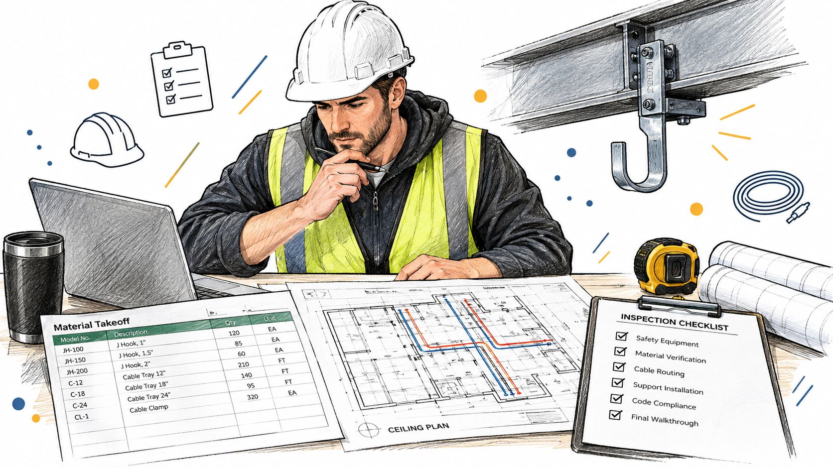
For crews working on structured cabling, audiovisual systems, PoE, coaxial, fire alarm, or control wiring, the hook isn't just a commodity fastener. Hook diameter, retainer configuration, mounting method, cable schedule, fill basis, and static-load rating all belong in the specification. A resource on fiber-optic network design and construction can also help teams coordinate pathway planning before installation begins.
The support geometry and spacing standards determine the starting point for that specification.
Table of Contents
- What a Caddy J Hook Does on a Real Jobsite
- Bend Radius and Pathway Standards That Drive J Hook Selection
- CAT HP J Hook Family and Where Each Size Fits
- Cable Count Versus Static Load The Two Capacity Checks
- J Hook Spacing Intervals and Why 5 Feet Is a Ceiling
- Substrate and Attachment Rules Every Installer Must Follow
- Plenum, Air Handling, and Power Separation Requirements
- Putting It Together A J Hook Selection Workflow
- When J Hooks Stop Working and Cable Tray Takes Over
- Procurement and Submittal Notes for Caddy J Hooks
What a Caddy J Hook Does on a Real Jobsite
A Caddy J hook supports a cable bundle at intervals instead of enclosing the entire route. Its curved profile gives installers a defined resting surface and helps maintain the cable's intended bend path through horizontal runs, transitions, and equipment approaches. The support should carry the bundle without crushing it or forcing it into a smaller radius than the cable manufacturer permits.
Cable ties and bridal rings solve a different problem. They can secure a bundle, but excessive tension or a narrow contact point can deform Category 6A, fiber, or other high-performance communications cable. A J hook leaves the bundle supported without turning the support into a compression point.
Cable tray remains the better comparison when the route requires a continuous pathway, dense cable management, or a defined route for a growing quantity of services. J hooks are often efficient for distributed communications runs where the building structure provides suitable attachment points and the bundle can be supported at planned intervals.
Practical rule: Treat the hook as a rated cable-support component, not as a convenient place to hang cable.
What belongs on the takeoff
A useful takeoff records more than a nominal hook size. At minimum, identify:
- Cable type: Separate Category 5e, Category 6, Category 6A, fiber, innerduct, PoE, and mixed-media bundles.
- Outside diameter: Use the actual cable schedule or manufacturer data, not a generic assumed diameter.
- Bundle geometry: Determine whether one bundle can remain together without exceeding fill or bend-radius limits.
- Attachment method: Confirm whether the hook will mount to a wall, ceiling structure, joist, or threaded rod.
- Environmental location: Establish whether the pathway is in an air-handling space and whether the selected product has the required listing.
This information gives the engineer and installer a defensible basis for product selection. It also gives the inspector something more useful than a box label or a “typical” cable count.
Bend Radius and Pathway Standards That Drive J Hook Selection
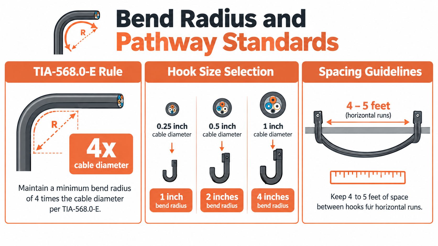
Bend radius comes before the model number. For copper cabling, the cited TIA-568.0-E guidance uses a minimum bend radius of four times the cable diameter. A typical Category 6A cable with an approximate 0.25-inch diameter therefore calls for at least a 1-inch bend radius at an appropriate J-hook support, as documented in the nVent CADDY CAT HP product guidance.
Fiber-optic cable requires substantially more clearance. The cited standards guidance specifies a minimum bend radius of 20 times the cable diameter, so a hook suitable for a copper bundle shouldn't automatically be approved for fiber. The actual cable manufacturer's requirements and the project specification govern where they are more restrictive.
The standards that inform the selection
The product documentation identifies TIA TSB-184-A and ISO/IEC TR 21925 as relevant guidance for cable support and bend-radius considerations. TIA-568.0-E establishes the copper bend-radius relationship, while the support and pathway guidance helps engineers translate that requirement into hook geometry, routing, and installation practice.
The practical selection sequence is straightforward:
- Confirm the largest cable diameter in the bundle.
- Apply the applicable bend-radius rule.
- Select a hook whose support geometry preserves that radius without crowding the bundle.
- Confirm that the cable can enter, rest in, and leave the hook without a sharp transition.
A 1-inch hook can be a practical starting point for smaller copper cable, while 1.5-inch to 2-inch supports may be more appropriate for larger Category 6A bundles or mixed pathways. Fiber runs commonly require the larger end of a product family because their bend-radius requirement is wider.
Excessive bending can impair transmission performance, increase insertion loss, or damage the cable. For broader structured cabling advice from Networking2000, coordinate pathway planning with the cable schedule rather than selecting supports after the route has already been crowded.
CAT HP J Hook Family and Where Each Size Fits
The CAT HP family is easier to evaluate as a progression than as a list of isolated SKUs. Start with the cable geometry and bundle size, then check the support's published fill capacity and structural rating independently.
The CAT16HP provides a 1-inch support diameter. The CAT32HP provides a 2-inch support diameter. Both are listed with a 60 lb static load rating, so the larger hook gives more cable area without automatically increasing the amount of weight the attachment can carry.
CAT16HP vs CAT32HP at a Glance
| Feature | CAT16HP (1 in) | CAT32HP (2 in) |
|---|---|---|
| Support diameter | 1 inch | 2 inches |
| Static load rating | 60 lb | 60 lb |
| Category 5e capacity at 70% fill | 20 cables | 90 cables |
| Category 6 capacity at 70% fill | 15 cables | 60 cables |
| Category 6A capacity at 70% fill | 10 cables | 35 cables |
| Typical selection logic | Smaller bundle and tighter support geometry | Larger bundle area and greater cable count capacity |
| Attachment options | Wall, ceiling, threaded rod, subject to approved installation | Wall, ceiling, threaded rod, subject to approved installation |
The published capacity values are calculated at a 70% fill rate, and they aren't universal answers for every cable. Actual outside diameter, jacket construction, bundle arrangement, future additions, and the attachment structure can change the practical selection.
CAT HP models also provide UL 2043 compliance for air-handling and plenum spaces, subject to project verification and installation requirements. The product family supports wall, ceiling, and threaded-rod attachment methods, but the selected mounting method still has to suit the substrate and load.
A submittal should identify the exact part number, diameter, cable type, mounting method, and environmental requirement. CAT HP is one available family, not a substitute for reviewing the entire cable-support design.
Cable Count Versus Static Load The Two Capacity Checks
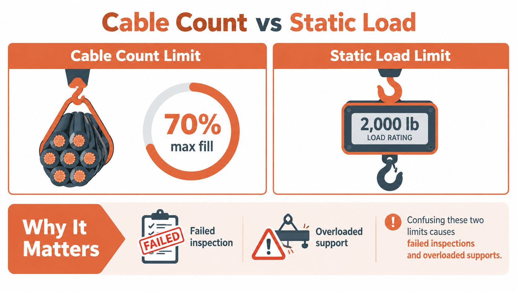
A Caddy J hook has two independent limits. Cable-fill capacity describes how much cable area fits within the manufacturer's fill assumption. Static load rating describes how much weight the hook assembly can carry. One does not replace the other.
For the 1-inch CAT16HP, the published figures at a 70% fill rate are 20 Category 5e, 15 Category 6, or 10 Category 6A cables. For the 2-inch CAT32HP, the corresponding figures are 90 Category 5e, 60 Category 6, or 35 Category 6A cables, also at a 70% fill basis, as shown in the CAT HP product data.
Both models carry a 60 lb static load rating. Increasing hook diameter can increase the available cable area, but it doesn't raise the allowable structural load.
A count that fits can still weigh too much
The same issue appears in larger supports. Published data for 3-inch CADDY J hooks increases capacity to 150 Category 6 cables and 80 Category 6A cables, while the listed static load remains 60 lb in the manufacturer-related product data. The cable count rises, but the load ceiling does not.
Use this workflow before approving a hook:
- Identify the cable outside diameter and weight. Use actual product data for each cable type.
- Apply the manufacturer's fill basis. Keep the bundle within the stated 70% fill assumption where that basis governs the published count.
- Calculate the combined weight. Include the cable bundle, not just the number of cables.
- Check the hook rating and attachment structure. The support and the building attachment must both carry the load.
- Reserve room for moves, adds, and changes. A pathway installed at its limit leaves no practical margin.
- Divide the bundle or change the pathway when either the fill or load limit is approached.
Port count is not a cable-support calculation. A “typical” value is not a submittal basis. The safe answer comes from the actual cable schedule, the manufacturer's assumptions, the structural attachment, and the expected future use of the pathway.
J Hook Spacing Intervals and Why 5 Feet Is a Ceiling
A five-foot interval gives a horizontal J-hook route its maximum commonly permitted span, not a default layout for every cable bundle. The cited TIA-569-C.9.7 and EN 50174-2 guidance for CAT HP installations identifies 5 feet, or 1.5 meters, as the upper limit as documented in the applicable specification sheet. Project specifications can require closer supports.
High-performance data and fiber-optic runs may need support at 3-foot spacing to control sag and preserve bend management, according to J-hook installation guidance. The shorter interval also helps where cable weight or route geometry makes a five-foot span impractical.
Set supports closer together at turns, vertical drops, equipment entries, risers, fire-rated penetrations, and points where several cables converge. These locations introduce more bending and movement than a straight, lightly loaded horizontal run.
Before releasing the layout, check four separate conditions:
- Fill: Keep the bundle within the hook's published cable capacity and stated fill basis.
- Structural load: Confirm the combined cable weight stays below the hook's static rating and the attachment capacity.
- Sag and bend control: Support the cable often enough to maintain its required bend radius and avoid an obstruction.
- Project requirements: Apply any specified 4-foot to 5-foot spacing or added supports, even when the nominal maximum is not exceeded.
Heavier PoE bundles, fiber, mixed media, vibration, and seismic conditions can all justify shorter intervals. Calculate support quantities from the cable schedule and add supports at transitions. Dividing route length by five feet alone can undercount the hardware and leave either the fill check or the structural-load check unresolved.
Substrate and Attachment Rules Every Installer Must Follow
A J-hook layout can pass its cable-fill check and still fail structurally. Verify both conditions separately: the hook must hold the cable bundle within its published capacity, and the attachment must transfer the combined load into a suitable building element.
Use the approved design and fastening method for the actual substrate. Structural framing or an appropriate joist connection can provide that support. A ceiling surface may be convenient without being designed to carry communications cable.
Choose the substrate before the fastener
Do not attach J hooks to:
- Ceiling-grid wire or grid components: They are not intended to carry communications-cable loads.
- Conduit or piping: Electrical conduit, sprinkler pipe, gas pipe, and plumbing serve other systems and do not replace structural support.
- HVAC ductwork: Ductwork is not an approved support point for the hook and bundle.
- Cable tray or ladder rack: These are pathway systems, not automatically suitable substrates for suspending another support.
- Unsupported surfaces: Correct any condition that cannot carry the combined hook and cable load before installation.
The J-hook installation guidance for structural attachment states this restriction directly. Match the fastener to the substrate, tighten it correctly, and fully seat the hook before pulling cable.
Orientation also affects the installation. For overhead mounting, keep the hook level so the bundle bears evenly. For vertical mounting, point the opening upward or sideways to retain the cables. Before rough-in inspection, confirm the substrate, fastener, hook seating, orientation, and cable route. A light bundle does not make ceiling-grid wire or another prohibited surface acceptable.
Plenum, Air Handling, and Power Separation Requirements
A ceiling void used for air handling changes the approval checks for a J hook. Confirm that the selected product is listed for that environment, then verify the cable rating, attachment method, and project standard. CAT HP models carry UL 2043 compliance for air-handling and plenum spaces. That listing addresses the support's fire-performance suitability, not every installation decision.
Power separation requires its own review. Low-voltage cables may share a ceiling space with branch circuits and other services, but the adopted electrical and communications standards govern the required distance, routing, or barrier. A plenum-rated support does not permit arbitrary proximity to power conductors.
Use the submittal to record three distinct approvals:
- Support listing: Identify the J hook and confirm its documentation covers the air-handling space.
- Cable suitability: Confirm that each communications cable has the rating required for the environmental location.
- Power separation: State the distance or barrier requirement and identify the project standard that establishes it.
Treat the published listing and the cable-fill figure as separate from structural capacity. The hook still needs an appropriate substrate and attachment method, while the bundle must stay within the manufacturer's stated cable and load limits.
For healthcare, education, government, and mission-critical facilities, include these records with the wider data and telecommunications infrastructure category procurement package. The project engineer and authority having jurisdiction determine which requirements apply.
Putting It Together A J Hook Selection Workflow
A dependable selection workflow converts the cable schedule into a documented installation decision, with separate checks for pathway fit and support capacity.
Start with the cable schedule
List every cable type in the proposed bundle. Record its outside diameter, required bend radius, and estimated weight. A mixed Category 6A and fiber run in a commercial corridor should not be sized from the Category 6A count alone. Fiber construction may require more bend clearance, even when its cable count is low.
Select the smallest hook diameter that preserves the required radius for every cable in the bundle. If the fiber needs more room than the copper, choose a support that accommodates both or place the media in separate pathways.
Run the two capacity checks
First apply the manufacturer's cable-count basis at 70% fill. Then calculate the actual bundle weight against the hook's static-load rating. These are different checks. A published cable count answers the area question, while the load calculation addresses the support and attachment. If either limit is approached, divide the bundle or select a larger support. A larger hook adds cable area, but it does not automatically raise the static-load rating.
Set supports no more than 5 feet, or 1.5 meters, apart, using the CAT HP specification sheet cited in the Spacing section above and the applicable TIA-569-C.9.7 and EN 50174-2 guidance. Tighten the layout at transitions, risers, equipment entrances, heavy concentrations, vibration or seismic conditions, and locations where cables need closer bend control.
Finish with the installation review
Verify that each attachment reaches the building structure or an appropriate joist connection. Confirm plenum suitability, power separation, hook orientation, and the fastening method's capacity.
A practical takeoff record should include:
- Cable schedule and outside diameters.
- Bend-radius basis and selected hook diameter.
- Cable-fill and static-load calculations.
- Spacing plan, including added supports at transitions.
- Substrate, fastener, and mounting method.
- Environmental listing and power-separation review.
- Product data and approval status.
The cable management category helps organize related pathway components. Keep each selection step with the submittal so the installation basis is clear during review and inspection.
When J Hooks Stop Working and Cable Tray Takes Over
J hooks and cable tray aren't competing answers for every route. J hooks work well when bundles remain distributed, attachment points are available, and the pathway doesn't need a continuous base. Cable tray becomes more practical when density, expansion, or coordination requirements make individual supports difficult to manage.
Watch for these crossover signals:
- Fill repeatedly approaches the limit: Larger hooks still reach the applicable fill basis across multiple routes.
- Support quantities grow rapidly: The takeoff needs more and more individual attachment points to maintain control.
- The ceiling becomes congested: Plenum space, transitions, and separation requirements become the binding constraints.
- Future capacity matters: Moves, adds, and changes would consume the remaining practical room in the J-hook layout.
- The specification calls for tray: A project requirement can settle the pathway choice regardless of the initial takeoff preference.
Adding a larger hook doesn't solve a structural load problem, and adding supports doesn't create a continuous pathway. When cable density and route coordination dominate the design, a tray system can provide a more controlled installation basis. The appropriate conduit, raceway, and cable support category can support evaluation of both approaches.
A coordinated procurement plan can stage J hooks and tray in the same shipment. That keeps the pathway decision tied to the engineering requirement rather than to whichever component arrives first.
Procurement and Submittal Notes for Caddy J Hooks
A defensible Caddy J hook submittal identifies the exact part number, hook diameter, mounting method, cable type, cable outside diameter, fill basis, and static-load rating. It should also show how the selected support fits the approved spacing, substrate, environmental, and separation requirements.
Don't approve an alternate because its cable count looks higher. A substitute may meet the cable-count requirement while exceeding the 60 lb static-load rating, using a different fill assumption, or requiring an attachment method that the project doesn't permit. Verify the product data and cable schedule together before accepting a substitution.
ATEK Distribution can assist with BOM review, hard-to-source components, manufacturer coordination, approved alternatives, and compliance documentation when shortages or lead-time changes threaten a mission-critical electrical project. The team can also help consolidate sourcing requirements so the J-hook decision remains aligned with the wider cable-management package.
ATEK Distribution helps contractors, engineers, facilities teams, and procurement professionals source Caddy J hooks, cable tray, and related electrical infrastructure with technical submittal support and approved-alternative review. Visit ATEK Distribution to request sourcing assistance, BOM support, or a project-specific quote.