
The replacement switch is ready, but the swap has stalled. Its uplink disappears beneath the raised floor, neither end has a readable label, and the drawing doesn't identify the route. Someone now has to trace a live connection during a maintenance window that was supposed to involve equipment, not infrastructure.
That's the practical test for a structured cabling data center design: can the team change active equipment without rediscovering the cable plant? The hardest decisions aren't patch-cord colors. They're cross-connect locations, pathway capacity, media compatibility, and whether the installed trunks can support future bandwidth generations without another cable pull.
Table of Contents
- Why Structured Cabling Shapes Data Center Uptime
- Data Center Cabling Hierarchy and Rack, Row and Zone Layouts
- TIA-942 and ISO/IEC Standards Behind the Design
- Copper and Fiber Distance Limits by Link Type
- Pathways, Space and Rack Density Planning
- Designing Redundancy and Upgrade Paths for AI Density
- Testing and Documenting the Installed Plant
- Confirm the Cabling Bill of Materials Before You Order
Why Structured Cabling Shapes Data Center Uptime
Structured cabling is standardized, documented permanent infrastructure that separates the building's cable plant from equipment connections. Instead of installing another dedicated route whenever equipment moves, technicians make controlled changes at accessible termination points.
Think of the installation as distinct layers:
- Permanent cabling: Backbone and horizontal links that remain through equipment refreshes.
- Cross-connects: Patch panels and distribution frames where technicians administer connections.
- Equipment connections: Removable patch cords and equipment cords that accommodate operational changes.
In a data center, higher equipment density, frequent changes, and demanding uptime expectations make this separation particularly valuable. A tangled office closet is inconvenient. An unidentified production uplink can turn a planned replacement into an outage investigation.
Sales of structured-cabling products installed in data centers increased by almost 35% worldwide in 2024, according to BSRIA. That activity makes disciplined administration important from the first installation, not something to add after expansion.
RDE Technologies' resource on business network infrastructure cabling provides useful context for separating permanent infrastructure from device connections. Data-center engineers must extend that discipline into hierarchy, standards, media selection, pathways, redundancy, testing, and procurement.
Design priority: Make the next maintenance action predictable. A technician should know which panel, port, and cable record to use before disconnecting anything.
Data Center Cabling Hierarchy and Rack, Row and Zone Layouts
Trace the physical route from the building entrance to the cabinet. Carrier services reach the main distribution area, backbone cabling connects distribution locations, and horizontal cabling reaches equipment areas. These are physical administration spaces, not a requirement to use a particular logical switching topology.
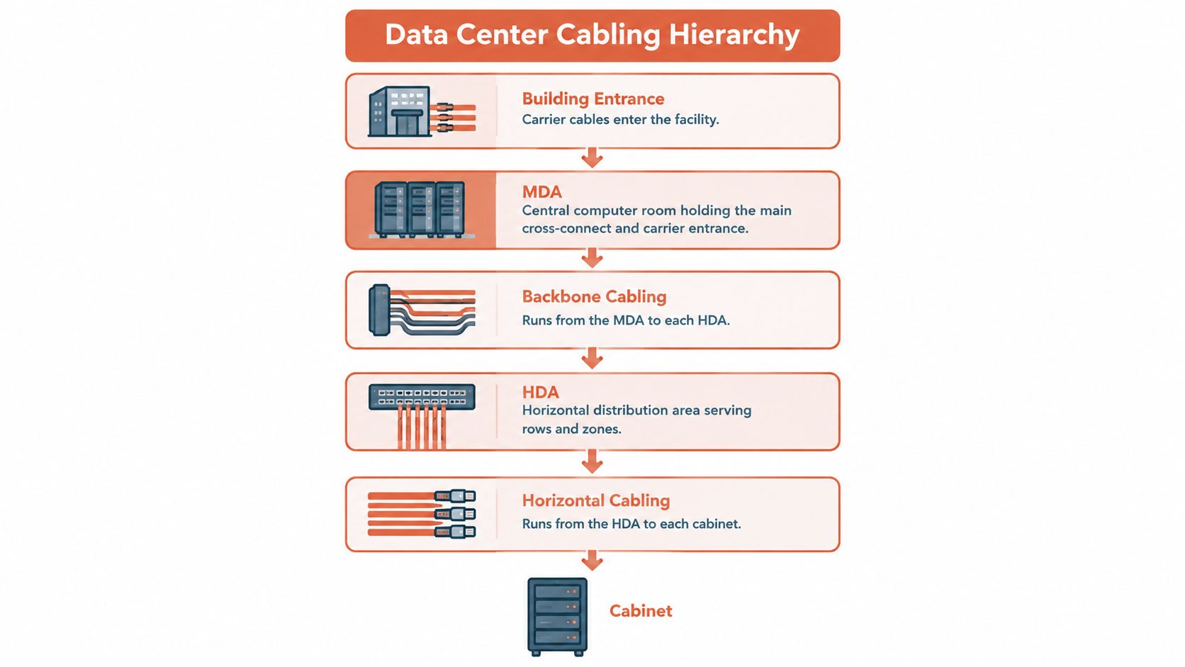
Distribution areas in a standards-based data center
| Distribution area | Typical location | Connects | Role in the design |
|---|---|---|---|
| Main Distribution Area (MDA) | Central computer room near the carrier entrance | Backbone to HDAs and external carrier cabling | Main cross-connect; highest fiber concentration |
| Horizontal Distribution Area (HDA) | Room or large zone, central to its EDAs | Backbone from MDA to horizontal links serving EDAs | Intermediate cross-connect; aggregates horizontal runs |
| Zone Distribution Area (ZDA) | Row or zone, optional | Distribution cabling to EDAs in its zone | Passive consolidation point; groups distribution toward equipment |
| Equipment Distribution Area (EDA) | Racks and cabinets | Horizontal cabling to equipment ports | Patch panels and cords serving equipment connections |
A ZDA can consolidate distribution serving a group of rows, but it doesn't automatically reduce the number of required circuits. Don't treat a passive consolidation point as an extra switching location or assume it removes downstream cable requirements.
Choose the administration location deliberately
Rack-level patching keeps panels inside each cabinet and suits compact clusters. It also distributes administration across more locations. Row-level patching concentrates access at the row end or middle, with manageable local equipment connections. Zone-level distribution serves several rows from a shared location, trading centralized access against larger bundles and longer routes.
For a hypothetical end-of-row design, measure the actual pathway to the farthest cabinet, including vertical transitions and service routing. Check the fixed run against the 90 m permanent-link baseline, leaving the conventional 10 m cord allowance described in the University of Naples data-center cabling teaching document.
The TIA-942-C infrastructure white paper recommends at least two optical fibers for horizontal and backbone cabling. That minimum supports duplex arrangements and migration flexibility, but redundant service still requires appropriately designed independent links.
Centralized, labeled cross-connects let technicians isolate a segment or replace equipment without disturbing fixed cable. Reserve spare ports, document fiber allocation, and check cabinet working space using the dimensions and management provisions illustrated by Vericom VC5 Series network cabinets.
TIA-942 and ISO/IEC Standards Behind the Design
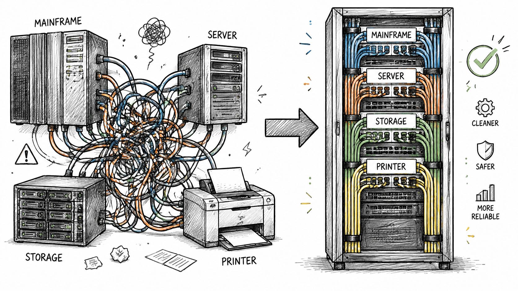
Data centers once accumulated proprietary point-to-point connections for mainframes, servers, storage, and peripherals. Those cables were difficult to identify and relocate, particularly beneath raised floors. A permanent, generic architecture replaced that equipment-specific approach with defined media, distribution areas, and administration practices.
As documented by Cabling Installation & Maintenance, ANSI/TIA-942 was published in April 2005, becoming the first standard from an accredited standards organization specifically addressing physical data-center infrastructure. Its foundational scope covered site space and layout, telecommunications cabling, tiered availability, and environmental considerations.
Use a coordinated standards set
TIA-942-C is the current edition used as this guide's reference, following Addendum 1, Addendum 2, TIA-942-A, and TIA-942-B. On an actual project, verify the edition specified by the owner rather than assuming a reference without a suffix means the latest publication.
Standards commonly referenced for data center cabling
| Standard | Scope | How it is used |
|---|---|---|
| ANSI/TIA-942, edition C used here | Data-center spaces, pathways, cabling, reliability, and environment | Primary architecture reference; verify the project edition |
| Applicable ISO/IEC cabling standards | International cabling architecture and performance framework | Coordinate international specifications, link models, and acceptance requirements |
For international projects, the engineer should identify the applicable ISO/IEC documents explicitly. Don't accept a supplier's statement of general ISO/IEC compliance as proof that a particular assembly meets the project's interface, performance, or testing requirements.
Specification check: A reference that says only “per TIA-942” leaves reviewers unable to identify the governing edition.
The standard establishes design requirements within its scope. Adopted codes and the authority having jurisdiction establish the applicable legal baseline. Procurement documents should identify both, resolve conflicts through the engineer, and retain manufacturer installation instructions as part of the installation package.
Copper and Fiber Distance Limits by Link Type
Distance references by data center link type
| Link type | Media | Distance reference | Design note |
|---|---|---|---|
| Horizontal copper permanent link | Balanced twisted pair, Category 6A | 90 m | Fixed-link allowance; retain cord capacity |
| Copper channel | Balanced twisted pair, Category 6A | 100 m | Includes up to 10 m of patch and equipment cords |
| Short copper server links | Category 8 | Below 30 m | Short data-center links, not a blanket horizontal replacement |
| Multimode fiber, internal links | Laser-optimized multimode | Roughly 100 m to 450 m | Application-specific; OM3 commonly specified around 150 m to 300 m |
| Direct MDA-to-EDA fiber | Laser-optimized multimode | Up to 300 m for applicable applications | Copper reference for the route is 100 m |
| Longer backbone fiber | Single-mode fiber | Transceiver-defined reach | Confirm the application and complete optical-loss budget |
The copper allocations, OM3 references, and direct-route comparison above follow the Belden Data Center Guide; the broader multimode range and short Category 8 application are described by the Fiber Optic Association. These are design references, not universal reach guarantees for every Ethernet application.
Distinguish the fixed link from the operating channel
The permanent link generally excludes removable equipment and patch cords. The channel represents the complete connection used by active equipment, including those cords. A route can look acceptable when measured across the room yet fail certification because the fixed portion exceeds its allowance.
Measure cable along the installed route, not across the floor plan. Include tray diversions, cabinet drops, and managed slack. Check the governing standard's channel model and manufacturer guidance where cord construction, connection arrangements, or operating conditions affect the permitted configuration.
Category labels don't override application limits. Cat 6A is a sensible choice for appropriate horizontal copper applications; Category 8 addresses a different, shorter-link use case. Replacing a horizontal specification with a higher category can introduce a reach mismatch rather than an upgrade.
Budget optical loss before selecting assemblies
Fiber reach depends on more than distance. Each mated connector and splice consumes part of the optical-loss budget, while contamination or tight bends can introduce additional loss. Correct polarity is also necessary for transmit and receive paths to align.
For a short internal link, multimode may be economical if the intended optics support the route and connection count. For longer backbones or uncertain migration requirements, evaluate single-mode alongside the transceiver cost and service model. Neither choice eliminates the need to calculate loss.
Specify permanent-link length, channel length, fiber class, connector-loss allowances, bend-radius limits, and certification requirements. A purchase description containing only Cat 6A or OM4 doesn't tell the installer what constitutes an acceptable completed link.
Pathways, Space and Rack Density Planning
Start at the entrance and mark every cross-connect before drawing tray routes. Establish backbone paths between the MDA, HDAs, and rows, then size horizontal distribution to cabinets. Routing cable first and finding termination space afterward usually creates awkward drops and inaccessible panels.
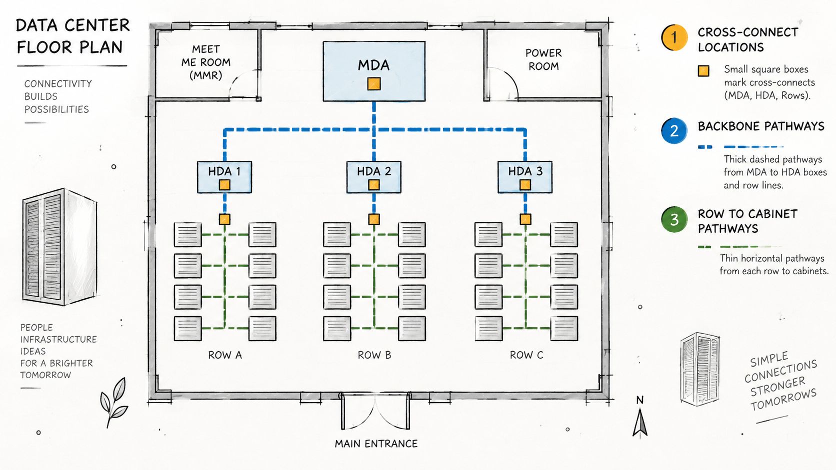
Reserve usable space, not an unspecified allowance
Pathway drawings should distinguish installed cable from capacity reserved for future trunks. Show where that reserve exists, including bends, wall penetrations, tray transitions, and cabinet entries. An open straight tray doesn't provide useful expansion capacity if the next penetration is already crowded.
Keep data cabling coordinated with power conductors and cooling pipework. The separation method must follow the adopted code, engineered arrangement, and cable and raceway manufacturer instructions. Don't apply a universal separation distance without checking the installation conditions.
Cable mass matters as well as fill. Bundled copper and high-count trunks load supports, while entry angles can force cables below their allowable bend radius. For smaller supported branches, evaluate CADDY J-Hook options against cable loading, support spacing, fastening conditions, and manufacturer instructions rather than treating hooks as interchangeable with tray.
Make the cabinet maintainable when it's full
Top-mounted patch panels can simplify overhead entry; middle-mounted panels may shorten local cord routes but consume equipment space. Select the position against the populated rack elevation, not an empty cabinet photograph. Vertical managers must accommodate connected cords while preserving access to power supplies, fans, and removable equipment.
Facilities sign-off should address:
- Structural loading: Tray, brackets, anchors, and their supporting structure suit the planned cable load.
- Route coordination: Power, cooling, access, firestopping, and maintenance clearances remain workable.
- Expansion access: Spare capacity extends through transitions and penetrations, not just open spans.
- Cabinet serviceability: Doors close, managers remain accessible, and cord routing fits the approved channel model.
Have the facilities team review the route with the installer and designer. Their maintenance access requirements often expose conflicts that aren't obvious in a telecommunications-only drawing.
Designing Redundancy and Upgrade Paths for AI Density
The densest connector arrangement isn't automatically the best long-term plant. It can save panel space while making inspection, cleaning, and retermination harder. If technicians can't service a connection without disturbing neighboring circuits, nominal density becomes an operational liability.
The Ethernet Alliance white paper on AI infrastructure reports that AI data centers can require up to eight times more fiber density than traditional facilities, with back-end networks using 400G and 800G transceivers and moving toward 1.6Tb links. Those transitions make pathway and trunk decisions consequential well beyond initial commissioning.
Compare usable migrations, not installed strands
Use this project-planning metric:
Cost per usable upgrade path equals installed plant cost plus expected cleaning, inspection, and retermination labor, divided by the number of future link generations the pathways and trunks can support without new pulls.
Evaluate 8-fiber, 16-fiber, and higher-count connectivity against actual candidate transceiver interfaces and breakout arrangements. A higher strand count isn't automatically more reusable if connector presentation, polarity, or loss prevents the intended migration.
Consider competing designs. A minimal trunk installation with no route reserve costs less initially, but increasing fiber count later requires another pull and another disruption. A design with reserved trunk and tray capacity costs more upfront but may allow the next generation through panel or cassette changes.
Separate redundancy from spare capacity
Spare fibers provide restoration and expansion options. They don't provide route diversity when they occupy the same vulnerable cable or pathway. Route redundant links so a single damaged support, penetration, or maintenance action doesn't disable both.
Review wire and cable tray options against that diversity requirement, not just fill. Document polarity, fiber allocation, interface assumptions, and optical-loss budgets for each proposed migration.
Replacement also needs an exit strategy. When equipment retirement or a larger refresh requires taking infrastructure out of service, Reworx Recycling's guidance to plan a secure data center shutdown provides relevant decommissioning context. Keep reusable trunks identifiable, and separate equipment disposition decisions from decisions about retaining the permanent plant.
Testing and Documenting the Installed Plant
Visual inspection identifies damaged jackets, poor routing, and missing labels. It doesn't demonstrate transmission performance. Commissioning requires recorded field measurements against the specified acceptance criteria.
Use the checklist below as a workflow aid, with the contract test schedule controlling the required measurements.
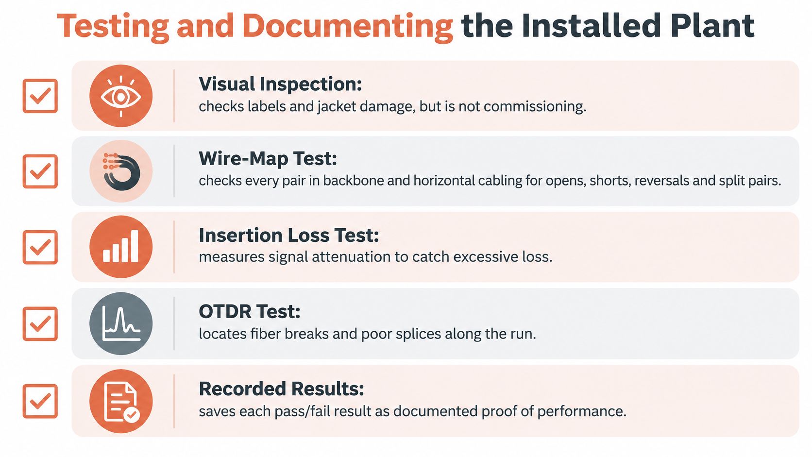
Test the failure modes separately
The NECA/BICSI installation guidance identifies wire-map testing for all pairs in backbone and non-horizontal balanced twisted-pair cabling, with results recorded for every segment. For optical fiber, it identifies optical-loss test-set measurements of length, polarity, and attenuation.
Field tests and what each one catches
| Test | What it measures | Failure it catches | Record kept |
|---|---|---|---|
| Wire map | All pairs in backbone and non-horizontal balanced twisted-pair cabling | Opens, shorts, reversals, and pair miswires | Result for every segment, tied to cable ID |
| Length | Installed cable length | Permanent link or channel over budget | Length per cable ID |
| Polarity | Transmit and receive orientation on fiber links | Crossed or reversed fiber pairs | Polarity result per fiber link |
| OLTS attenuation | Connector, splice, and cable loss | Link budget exceeded by dirty or poor connections | Measured loss per fiber link against budget |
- Inspect and identify: Confirm endpoint labels and physical condition before connecting test equipment.
- Certify copper: Use the correct permanent-link or channel adapters and the specified category test limit. Wire map alone isn't full performance certification.
- Measure fiber: Inspect and clean interfaces, verify polarity, and measure attenuation using the specified reference method.
- Investigate failures: Use an OTDR where specified or useful for locating fiber events. It doesn't replace the required end-to-end OLTS acceptance measurement.
The following video provides additional installation context; use the project's test requirements for acceptance.
Deliver records facilities can use
Tie every result to a unique cable or fiber identifier. Retain native test files, test limits, reference settings, equipment details, and final passing results after remediation. A summary spreadsheet without the underlying measurements makes later investigation harder.
Hand over those records with as-built drawings, rack elevations, fiber allocations, and patching schedules at project close. The facilities team should be able to select a cable ID and retrieve its endpoints and acceptance result without tracing the installed route again.
Confirm the Cabling Bill of Materials Before You Order
A trunk and cassette can look compatible on a purchase order yet produce the wrong fiber presentation at the transceiver. Fixing that mismatch after installation can require replacement assemblies, revised patching, and another test cycle. Resolve interfaces before comparing supplier totals.
The bill of materials (BOM) should describe an operable system, not a collection of individually acceptable parts. Include the transition components, support hardware, management accessories, and test obligations that connect the headline items into a usable installation.
Review the complete connection
Use a connection schedule alongside the BOM:
- Media and optics: Confirm fiber type or copper category against the intended application and complete link budget.
- Connector system: Verify mating interfaces, connector gender where applicable, keying, polarity method, and cassette presentation.
- Trunks and spare capacity: Reconcile installed assemblies with port allocations and the expansion capacity shown on drawings.
- Patch cords: Select lengths from actual routing, including managers and equipment service positions.
- Installation hardware: Include tray transitions, supports, cabinet entries, bonding provisions where applicable, and identification materials.
Ask suppliers for product submittals, compliance documentation, and installation instructions before release. Where the contract requires Buy American Act or Trade Agreements Act documentation, request project-relevant evidence rather than assuming the distributor's location establishes product eligibility.
Control substitutions and phased delivery
An alternate is acceptable only after the responsible reviewer checks it against the same interfaces, loss budget, installation constraints, and test requirements. Similar descriptions aren't enough. A connector substitution can change the number of mated interfaces or require a different polarity arrangement.
A sourcing partner can review the BOM against the specification, coordinate manufacturer availability, and identify candidates for engineering approval when items have long lead times. Material consolidation, kitting, and staged delivery also help installers receive complete work packages instead of cabinets without managers or trunks without the correct cassettes.
For a structured cabling data center project, request a quote against the approved connection schedule and specification, not just a parts list. Include required delivery phases, documentation, and acceptable-alternate procedures so procurement can compare complete offers rather than incomplete initial prices.
ATEK Distribution offers structured cabling and datacom products, BOM review, manufacturer coordination, and sourcing support for hard-to-find components and proposed alternatives. Visit ATEK Distribution to request a project-specific quote, and include your connection schedule, link requirements, compliance needs, and installation phases so the team can help assemble a coordinated procurement package.