Car Flex Connector Guide Types Selection and Install

You're probably here because someone asked for a car flex connector, and the term was too vague to order from. One person means a braided exhaust section. Another means a flex cable connector inside a display, sensor module, or control board. A third might even mean a liquidtight flexible conduit fitting used to route wiring in harsh vehicle-adjacent environments. That confusion is where misorders start.

In distribution, this is one of the more common avoidable mistakes. A buyer searches by slang, sees a part that looks close enough, and only later finds out the temperature range, retention method, mounting style, or mating side was wrong. By then the truck is down, the installer is waiting, or the panel shop has to rework a harness.

The useful way to handle a car flex connector request is simple. Start with function, then location, then environment, then interface. If the part carries exhaust gas, you're in one category. If it carries signals or power through a flexible cable, you're in another. If it protects conductors in a routed pathway, that's a third conversation entirely.

Table of Contents

Introduction to Car Flex Connectors and How This Reference Works

A practical example makes the problem clear. A fleet buyer calls for a “front flex connector” after hearing vibration near the engine bay. The shop means an exhaust flex connector. Later that same day, a technician asks for a “flex connector” for a head unit repair and means a flat flex cable connector on a board. Those are unrelated parts with different materials, failure modes, and buying questions.

The term is broad enough that the wrong first assumption wastes time. Worse, it can send the job in the wrong direction. An exhaust buyer needs to think about placement, heat, movement, and construction. An electronics buyer needs to think about pitch, current, retention, insertion method, and service access.

What buyers usually need to confirm first

Before you compare brands or part families, pin down these basics:

  • Function of the part. Is it moving exhaust gas, terminating a flex cable, or sealing conduit around conductors?
  • Where it lives. Near manifold heat, behind a dashboard, inside a module, or at an enclosure entry.
  • What causes failure. Vibration, thermal cycling, pullout, intermittent contact, fluid exposure, or bad insertion.
  • What must mate with it. Pipe sections, FFC/FPC tails, flex-to-board interfaces, or threaded hubs and conduit.

That four-part check catches most bad line items early.

What's covered here

This guide stays focused on the two meanings that trip buyers most often. First, exhaust flex connectors used to absorb vibration and thermal expansion in the exhaust path. Second, electronics flex connectors such as FFC/FPC and flex-to-board styles used in modern vehicle electrical systems.

Because many buyers also use “Carflex” to describe flexible conduit systems and fittings, this reference also includes liquidtight flexible conduit connectors as a system-level comparison point. That matters most for contractors, upfitters, integrators, and maintenance teams routing conductors in wet, dirty, or vibration-prone areas.

Practical rule: If you can't name what the connector mates to on both ends, you're not ready to order it.

Two Meanings of Car Flex Connector You Must Distinguish First

The biggest split is between exhaust flex connectors and electronics or wiring flex connectors. They solve completely different problems.
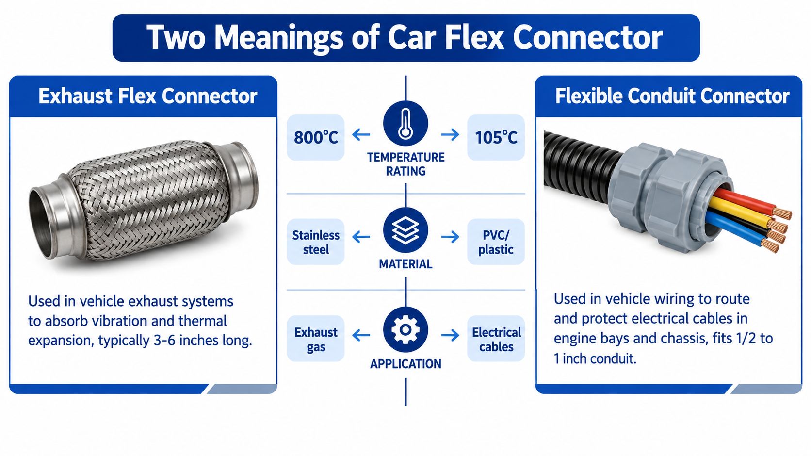
A comparison chart showing two types of car flex connectors, exhaust pipes and electrical wiring conduits.

Exhaust flex connector

This is the braided or formed flexible section in the exhaust system. Its job is mechanical. It takes up movement from engine motion, road vibration, and thermal expansion so the rigid exhaust sections don't crack or transmit as much noise.

Industry guidance notes these parts were designed to reduce noise and vibration, are commonly installed between the exhaust manifold and front pipe in front-wheel-drive vehicles, and may need working ranges up to 650°C or 800°C depending on location, as described in Triscan's exhaust flexible connector guidance. That's why front-pipe placement and rear-muffler placement are not the same buying decision.

Typical buyer questions are different here:

  • Where in the exhaust will it sit
  • How much heat will it see
  • How much movement must it absorb
  • Is the failure from cracking, fraying, or poor fitment

Electronics flex connector

This one lives in the vehicle's electrical architecture. It joins a flexible flat cable or flexible printed circuit to a board, wire assembly, or compact module. The job here is electrical continuity in a small space, with enough retention to survive service handling and vehicle conditions.

This category exists because vehicle electronics became much denser over time. Connector history references trace flex cable connectors as a distinct category back to the 1970s, and by the 1990s rising wiring complexity and networked electronics had already pushed connector design toward higher reliability and compactness, according to the Connector Book connector timeline.

Fast self-selection test

If you need a quick divide, use this:

Need on the vehicle You likely need What matters most
Absorb engine movement in exhaust path Exhaust flex connector Heat, placement, construction
Join a flat cable to a board or compact module FFC/FPC or flex-to-board connector Pitch, retention, current, temperature
Route and protect conductors through a flexible pathway Flexible conduit connector Seal, thread fit, conduit compatibility

If the part carries gas, don't shop it like a signal connector. If it carries signal, don't shop it like a pipe repair part.

A lot of returns happen because buyers compare only the outside shape. Function has to come first.

Carflex Flexible Conduit System Overview and Core Components

When buyers say “Carflex,” they sometimes mean a liquidtight flexible conduit system rather than an exhaust or board-level connector. That's common in electrical contracting, vehicle upfit work, industrial skids, and equipment enclosures where conductors need both protection and some movement tolerance.
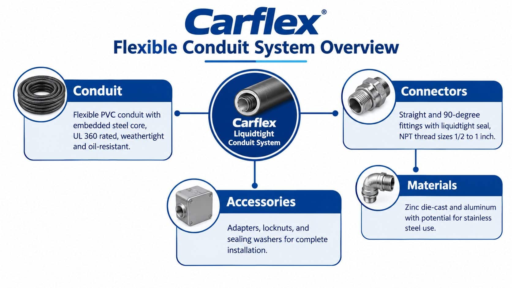
A diagram illustrating the Carflex flexible conduit system with conduits, connectors, and various installation accessories.

What the system actually includes

A flexible conduit system is not just a tube with a fitting on the end. It's a matched set of parts:

  • Conduit body for routing and bend allowance
  • Connector or fitting for entry into a box, enclosure, or hub
  • Locknut, sealing washer, or adapter depending on the mounting style
  • Enclosure interface that has to match thread and sealing requirements

If one piece is mismatched, the whole run suffers. The usual field problem isn't dramatic failure. It's a slow issue like poor sealing, movement at the connector throat, or a conductor pathway that gets stressed because the fitting angle was wrong.

Why people choose flexible conduit systems

Rigid raceway works when the path is stable and space is generous. Flexible conduit gets chosen when the route has vibration, movement, awkward geometry, or wet and dirty exposure. That's why it shows up around machinery, equipment skids, roof penetrations, outdoor enclosures, and retrofit work where exact alignment is unrealistic.

For contractors comparing raceway options, ATEK's conduit, raceway, and cable support categories are the kind of product grouping that helps narrow whether the application calls for flexible conduit fittings or a different raceway family entirely.

The connector's real job

The connector in this system does more than “attach” the conduit. It has to:

  • Maintain mechanical retention so the conduit doesn't back out under motion
  • Preserve the seal where moisture, washdown, or grime are present
  • Match the hub or entry point without improvised adapters that create leak paths
  • Avoid over-compressing the conduit jacket during tightening

What works is using a fitting matched to both conduit type and enclosure entry. What doesn't work is assuming all flexible conduit fittings grab and seal the same way. They don't.

A connector that fits physically but doesn't compress the jacket correctly can look installed and still fail in service. That's the sort of mistake that stays hidden until inspection, corrosion, or intermittent electrical trouble shows up later.

How to Choose the Right Car Flex Connector for Your Application

Selection gets easier once you stop treating all flex connectors as one bucket. Buyers do better when they sort by application first, then by the few specs that control fit and life.

Start with the environment, not the catalog page

For exhaust flex connectors, begin with location in the system. Front-end positions closer to engine heat demand more thermal margin than rear sections. The “best” choice depends on installation location, thermal loading, and engine layout. That's where many general retail listings fall short. They show a generic replacement, not a use-case match.

For electronics flex connectors, the environment means vibration, service access, and operating temperature. A board-level connector in a compact infotainment assembly is not the same selection problem as one in a harsher module with more thermal cycling.

Use the core filters that actually matter

For electronics connectors, current market demand is rising because vehicles carry more electronics and more electrified subsystems. One market report values the global flexible flat cable connector market at $4.8 billion in 2025 and projects $9.1 billion by 2034 with a 7.3% compound annual growth rate. The same report says Asia Pacific held 48.6% of global revenue, and a single battery electric vehicle typically uses 90 to 150 individual FFC and FPC connectors across systems such as battery management, infotainment, ADAS, onboard chargers, and thermal modules. It also states global EV sales exceeded 17 million units in 2025. Those figures are from the Dataintelo flexible flat cable connector market report.

That trend matters because it changes the buying mindset. These aren't niche parts anymore. They're standard interconnect decisions in electronics-dense platforms.

Car Flex Connector Selection Matrix by Application

Application Key Requirement Recommended Connector Attribute
Front exhaust section Thermal load and movement absorption Exhaust flex connector chosen by placement and heat exposure
Rear exhaust repair Vibration isolation with lower thermal load than front location Exhaust flex connector matched to downstream location
Infotainment flex tail Compact board connection and controlled insertion FFC/FPC connector with matching pitch and ZIF retention where service access matters
Sensor or compact module Stable contact in small package Flex-to-board connector with automotive-grade validation and controlled contact resistance
Vehicle-adjacent enclosure or equipment wiring Sealed conductor entry with movement tolerance Liquidtight flexible conduit connector matched to conduit and hub

The practical decision tree

Use this order when reviewing a part line:

  1. Define the mating interface. Pipe to pipe, flex tail to board, or conduit to enclosure.
  2. Match the working environment. Heat, vibration, fluid exposure, or service handling.
  3. Check physical geometry. Pitch, orientation, angle, thread, hub, or install space.
  4. Review retention method. Braid construction, ZIF latch, contact system, or conduit compression seal.
  5. Confirm service expectations. One-time install, repeated access, or long-term fixed assembly.

A connector that barely fits on paper usually fails in the field. Leave room for assembly reality, not just drawing reality.

Detailed Connector Types and Specifications Explained

The part families separate cleanly. If you're buying by appearance alone, skip that habit. Construction details decide whether the connector survives the application.
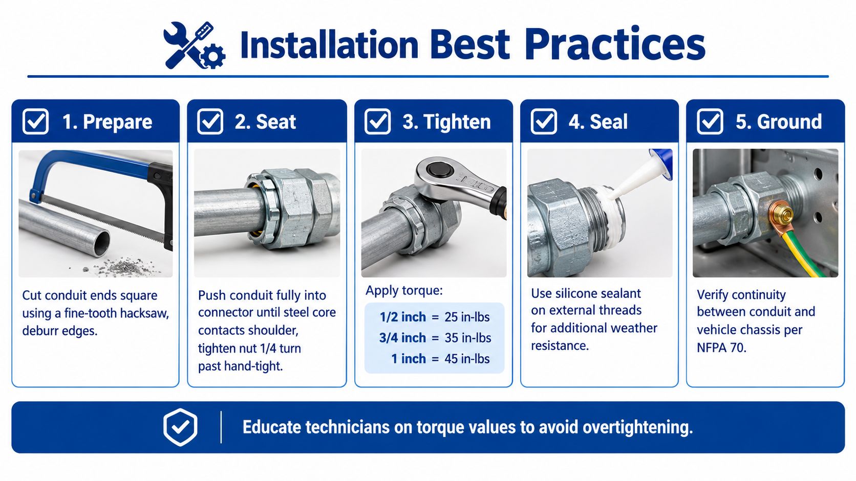
A five-step guide on installation best practices for conduit flex connectors including preparation and grounding.

Exhaust flex connectors by use case

An exhaust flex connector is selected around movement and heat, not signal specs. The main trade-off is simple. A unit installed near the manifold sees much harsher heat than one farther downstream, so the buyer has to account for location first. A generic “universal” listing often ignores that.

What works is specifying by actual placement. Front-pipe service and rear-section service are different jobs. What doesn't work is replacing a hotter-location connector with a lower-temperature option just because the diameter looks close.

Automotive flex-to-board connector families

For signal interconnects in vehicles, automotive qualification references matter more than marketing language. Product documentation for relevant connector families cites USCAR-T2V2 and LV-214 S3 as benchmark standards for high-reliability vehicle interconnects. One example flex-to-board family specifies 1.80 mm pitch, 1 A nominal current per contact, 60 VAC/VDC rating, 25 mΩ maximum initial contact resistance, 500 VAC dielectric withstand, and -40°C to +125°C operating range, as shown in this automotive connector solutions datasheet from Mouser.

Those numbers tell you what kind of application the connector belongs in. This is a compact signal interconnect envelope, not a catch-all power connector.

FFC and FPC ZIF connectors

A representative 0.50 mm-pitch right-angle ZIF connector specifies 30 mating cycles, 30 gf/pin FFC/FPC retention force, 100 gf minimum terminal and stator-plate retention, 50 V AC/DC rating, 0.5 A current rating, 500 MΩ minimum insulation resistance, and -40°C to +105°C operation, according to the Amphenol F305 FFC/FPC datasheet.

Those figures matter in a very practical way:

  • Pitch controls fit. If the cable pitch is wrong, nothing else matters.
  • Current rating sets limits. Don't treat a compact signal connector like a general-purpose power path.
  • Mating cycle rating affects service decisions. Frequent bench rework or repeated field access can wear small ZIF styles faster than buyers expect.
  • Retention force matters under vibration. A marginally supported tail can turn a good connector into an intermittent fault.

A lot of intermittent electronic faults come from cable-side mistakes, not bad connectors. Cable thickness, stiffener thickness, and insertion method all affect whether the ZIF mechanism holds as intended.

For buyers comparing fitting and conduit hardware rather than board-level parts, ATEK's flexible conduit fittings product category is one example of where straight, angled, and compatibility-specific fitting options are grouped by application.

Here's a quick visual before the install discussion gets more detailed.

Installation Guidance and Best Practices for Reliable Connections

Selection errors cause one class of problems. Installation errors cause another, and they often look like product defects when they aren't.
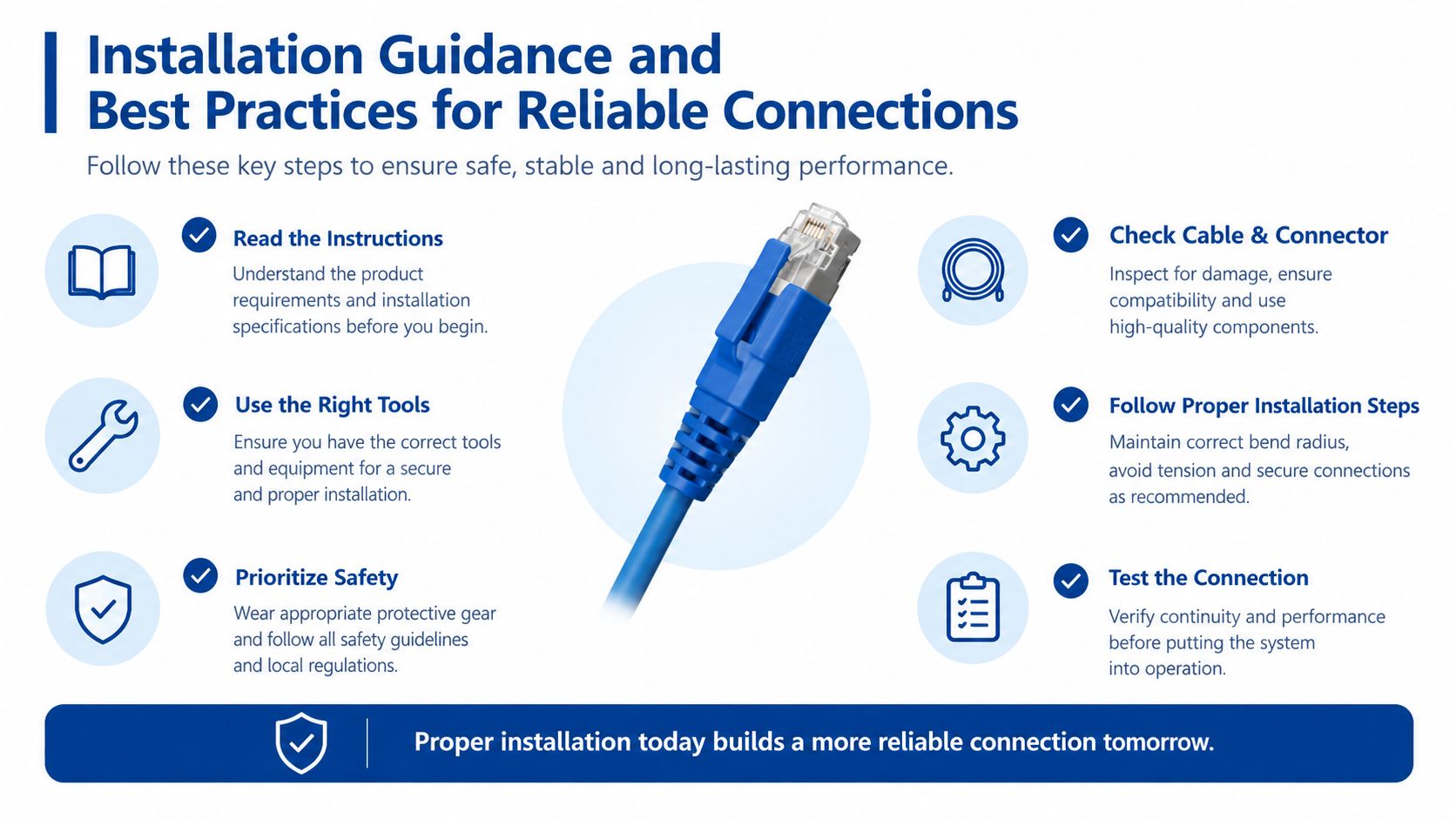
An infographic detailing essential installation guidance and best practices for ensuring reliable network cable connections.

For conduit and fitting assemblies

Most failures start at preparation. If the conduit end is rough, out of square, or not fully seated, the connector can't do its job. Installers then tighten harder to compensate, which often makes things worse.

Use a simple discipline:

  • Cut cleanly so the end seats correctly.
  • Inspect the jacket and core before insertion.
  • Seat the conduit fully instead of stopping when resistance first appears.
  • Tighten to secure, not crush. Over-tightening can distort the interface and shorten service life.
  • Verify continuity and sealing after the assembly is fixed in place.

For FFC and FPC connectors

Small flex connectors fail most often during insertion. The common causes are crooked entry, upside-down contact orientation, wrong stiffener thickness, or forcing the actuator.

What works:

  1. Open the latch fully before insertion.
  2. Confirm the exposed conductor side matches the connector contact orientation.
  3. Insert the tail straight, not at an angle.
  4. Check that the stiffened tail seats evenly across the width.
  5. Close the latch without forcing it.

What doesn't work is “feeling it in” on a tiny connector in poor lighting. That's how traces get scarred and latches get cracked.

On ZIF parts, the cable usually tells the truth before the connector does. If the tail shows scrape marks, bent reinforcement, or uneven seating lines, pull it and correct the setup.

Inspection habits that prevent repeat failures

After installation, don't stop at continuity alone. A connector can pass an initial electrical check and still be one vibration cycle away from trouble.

Use a short verification routine:

  • Mechanical check for pullout resistance or latch engagement
  • Visual check for full insertion and no jacket damage
  • Routing check so the cable or conduit isn't carrying strain at the connector throat
  • Environmental check for heat, splash, abrasion, and unsupported movement

For termination supplies, accessories, and related install hardware, buyers often need the companion items as much as the connector itself. A category view like ATEK's wire termination and supplies is useful when the original issue is incomplete installation hardware rather than the connector body.

Common Compatibility Issues and Troubleshooting Solutions

Field troubleshooting goes faster when you match the symptom to the likely mismatch.

Exhaust noise or early repeat failure

If an exhaust flex connector fails early, the first question is placement. A connector chosen without enough thermal margin for its location won't last the way the buyer expects. The next check is movement. If the system is carrying more engine motion than the flex section was meant to absorb, the failure will come back even after replacement.

Corrective action is usually to verify actual install position, not just nominal pipe size.

Conduit fitting loosens or leaks

This usually traces back to one of three issues:

  • Wrong conduit-to-fitting match
  • Poor seating at the fitting throat
  • Over-tightening that distorted the sealing interface

The fix isn't just “tighten again.” Remove, inspect the conduit end, confirm compatibility, and rebuild with the correct fitting geometry if necessary.

Intermittent board-level signal problems

On electronics flex connectors, intermittent faults are often dimensional. The cable may have the wrong pitch, wrong exposed-contact orientation, or the wrong tail build for the connector. In service work, the latch may also be partially closed over a misaligned tail.

Check these fast:

Symptom Likely cause First correction
No contact on all positions Wrong pitch or wrong orientation Confirm cable and connector match
Some positions intermittent Crooked insertion or poor latch closure Reinsert and inspect tail alignment
Works on bench, fails in vehicle Weak retention or poor strain routing Support the tail and review retention method
Damage during service Too many repeated insertions for the connector style Replace worn connector and review service practice

Overheating or discoloration

On signal connectors, overheating usually points to using a compact connector outside its intended current envelope or to poor contact integrity from bad insertion. On conduit systems, visible jacket distress near a fitting can indicate mechanical stress or exposure the assembly wasn't chosen for.

The shortest path to a real fix is to stop assuming all “flex connectors” are interchangeable. They aren't, even within the same general family.

Quick Reference Glossary and Cross Reference Lookup

This is the part most buyers end up bookmarking.

Glossary of terms buyers actually use

  • Exhaust flex connector. Flexible section in the exhaust path that absorbs vibration and thermal expansion.
  • FFC. Flexible flat cable used for compact electrical interconnects.
  • FPC. Flexible printed circuit, often used similarly to FFC in compact vehicle electronics.
  • ZIF connector. Zero insertion force connector that uses a latch or actuator to secure the flex tail.
  • Flex-to-board connector. Connector family joining a flexible circuit or cable to a rigid board.
  • Pitch. Center-to-center spacing of conductors or contacts. This must match.
  • Retention force. Mechanical holding force that keeps the cable or terminal in place.
  • Liquidtight flexible conduit connector. Fitting used to terminate flexible conduit into a box, enclosure, or hub while preserving a sealed pathway.

Fast reorder checklist

Before reordering a car flex connector, verify these items from the failed or existing part:

  • Application identity. Exhaust, board-level electronics, or conduit system.
  • Mating side details. Pipe ends, cable tail format, board connector series, or hub thread.
  • Critical environment. Heat, vibration, moisture, chemical exposure, or service access.
  • Dimensional fit. Pitch, orientation, angle, conduit size, or mounting style.
  • Failure pattern. Leak, pullout, intermittent contact, worn latch, or thermal distress.

Cross reference by buying situation

If the request says “front exhaust flex,” start with location and heat exposure.

If the request says “radio ribbon connector” or “screen flex connector,” start with pitch, orientation, current, and retention style.

If the request says “Carflex connector” from a contractor or maintenance team, ask whether they mean a flexible conduit fitting entering a box or enclosure. In practice, that's often what they mean.

Buy by interface first, slang second. That one habit eliminates a surprising number of wrong orders.

The buyers who make the fewest mistakes don't memorize every connector family. They ask sharper first questions, capture the mating details, and refuse to substitute across categories just because a product title uses the same word.


ATEK Distribution helps contractors, fleet support teams, engineers, and procurement buyers source conduit fittings, electrical infrastructure components, and hard-to-match accessories when a vague “car flex connector” request needs to become a correct line item. If you need help narrowing conduit-related options, reviewing compatibility, or sourcing difficult electrical products, visit ATEK Distribution.
Cable Ferrule Crimp Guide for Clean Terminations

You've just stripped a flexible conductor for a control panel terminal. The copper strands fan out, one slips under the clamp, and the finished connection looks acceptable until vibration or repeated heating exposes the weakness. A proper cable ferrule crimp prevents that failure by forming the strands into a controlled termination that the terminal can clamp consistently.

Appearance is only the first check. A reliable termination depends on the conductor, ferrule, die profile, crimp position, tool condition, and verification method working together. The useful question isn't whether the sleeve looks compressed. It's whether the connection matches the applicable requirements and withstands the pull force expected for its conductor size.

Table of Contents

Why Cable Ferrules Exist and When They Apply

A stranded conductor can fail at the terminal even when the insulation and copper look undamaged. Individual strands may spread under a screw or spring clamp, creating uneven pressure and leaving the connection vulnerable to movement and oxidation. A ferrule holds the strands in a metal sleeve, presenting the terminal with a defined contact area rather than a loose bundle.

Ferrules entered widespread European practice in the latter half of the twentieth century as manufacturers sought to protect stranded copper conductors at terminal screws. That purpose remains practical: the sleeve controls the conductor mechanically before the terminal applies clamping force. The relevant practice is reflected in the DIN 46228 series, along with EN 60999-1 and EN 60352-2, as outlined in Phoenix Contact's standards guidance.

Match the conductor before choosing the sleeve

Select the ferrule from the conductor's cross-section, not from color alone. Insulated ferrules use standardized dimensions and color identification under DIN 46228-1. Ferrules intended for fine-stranded conductors require the tighter dimensional considerations associated with DIN 46228-4. The sleeve should accept the entire strand bundle without folding strands, shaving copper, or leaving empty space inside the barrel.

Conductor construction also affects the termination. Fine-stranded cable contains more individual strands, so insertion and compression need closer control. A tinned end presents another condition because solder can stiffen the conductor near the clamp. Treat it differently from clean, flexible copper prepared for a ferrule.

Practical rule: Use a ferrule when a stranded conductor enters a screw or spring terminal rated to accept ferrules, especially in control, instrumentation, safety-related, or vibration-exposed work. Confirm the terminal manufacturer's instructions before making the method standard.

Ferrule families commonly cover conductor cross-sections from 0.5 to 50 mm², roughly AWG 20 to 1/0. The range describes the product family, not the capacity of one crimp tool. Check the ferrule and die ratings against the actual conductor size, then verify the finished termination with the applicable pull-force requirement. A sleeve that fits physically can still be the wrong choice if its dimensions, conductor class, or crimp profile do not match the terminal and tool.

Choosing a Ferrule Crimp Tool for the Job

The tool profile determines how the sleeve deforms, how evenly it compresses the strands, and how well the finished end fits the terminal. Three families cover most panel and harness work: square-profile ratcheting tools, trapezoidal-profile tools, and four-indent pneumatic or heavy-duty ratcheting crimpers.

A square-profile ratcheting tool is the practical daily choice for many control-panel benches. It's quick, relatively affordable, and the completed ferrule has flat sides that seat neatly in many spring and screw terminals. Its limitation is coverage. A die window may handle a useful group of conductor sizes, but it won't automatically make the tool suitable for every ferrule in the drawer.

Trapezoidal-profile tools produce a compact, repeatable deformation favored in many European panel-building environments. They can give a clean termination that inserts smoothly into spring terminals, but the tool and ferrule still need to be matched. A neat shape doesn't compensate for a die that's outside its rated range.

Four-indent tools compress the sleeve from multiple directions and can produce a strong, near-round termination for fine-stranded cable and demanding harness work. They cost substantially more than everyday hand tools, so the investment makes sense where the work involves production volume, fine-stranded conductors, or documented pull-force requirements. For occasional panel repairs, their capability may be unnecessary.

Tool family Typical AWG / mm² range Crimp profile Relative cost Best fit for
Square-crimp ratcheting hand tool Depends on the marked die window Square Lower General control-panel wiring and service work
Trapezoidal-crimp ferrule tool Depends on the selected die Trapezoidal Moderate Repeatable European-style panel wiring and spring terminals
Four-indent pneumatic or ratcheting tool Depends on the ferrule and die set Four-indent, near-round Higher Fine-stranded cable, harness production, and documented quality programs

Check more than the profile. The important details are the rated conductor range, handle force at that range, die marking, ratchet completion, and calibration basis. A tool that merely says “automatic” or “self-adjusting” isn't automatically compliant with a particular ferrule standard. Look for documentation connecting the tool and ferrule system to the required dimensions and test method.

For sourcing, ATEK Distribution's tools and testing selection is one place to compare crimping and verification equipment alongside the rest of a project's electrical requirements. The tool still has to be selected against the conductor, ferrule, terminal, and acceptance procedure.

Preparing the Conductor and Ferrule

A pull test can expose a preparation error before the ferrule ever reaches the terminal. Measure strip length from the ferrule collar and barrel depth, then adjust the stripper so insulation finishes where the collar can support it. The copper should extend only slightly beyond the sleeve shoulder. Phoenix Contact's technical guidance limits conductor protrusion to no more than 1 mm in its validation workflow.

Use a sharp, correctly adjusted stripper. A nicked strand reduces the conductor's strength, even when the defect disappears inside the barrel. After stripping, trim fanned strands cleanly. Do not twist them tightly or push loose filaments back into position.

Build the fit in a controlled sequence

Match the ferrule to the conductor cross-section and the specified ferrule family. DIN 46228-1 assigns a color band to each cross-section, and adjacent sizes such as 1.0 mm² and 1.5 mm² can look alike in poor light. Select from a labeled strip magazine or tray, then confirm the printed size against the manufacturer's documentation. For two conductors, use a twin ferrule rated for that arrangement rather than forcing both wires into a standard sleeve.

Inspect the barrel before insertion. It must be clean, undamaged, and free of deformation. The conductor should enter straight until the insulation meets the inside of the collar. Keep the fit dry: lubricants and flux can affect the termination, while residue or visible oxidation can interfere with reliable contact.

A strand folded backward inside the barrel creates a hidden void or stress point that may reduce measured pull force. ATEK Distribution's wire and cable range can help source the conductor alongside the ferrule specification when the materials need to remain under one controlled purchasing process.

Crimping the Ferrule End to End

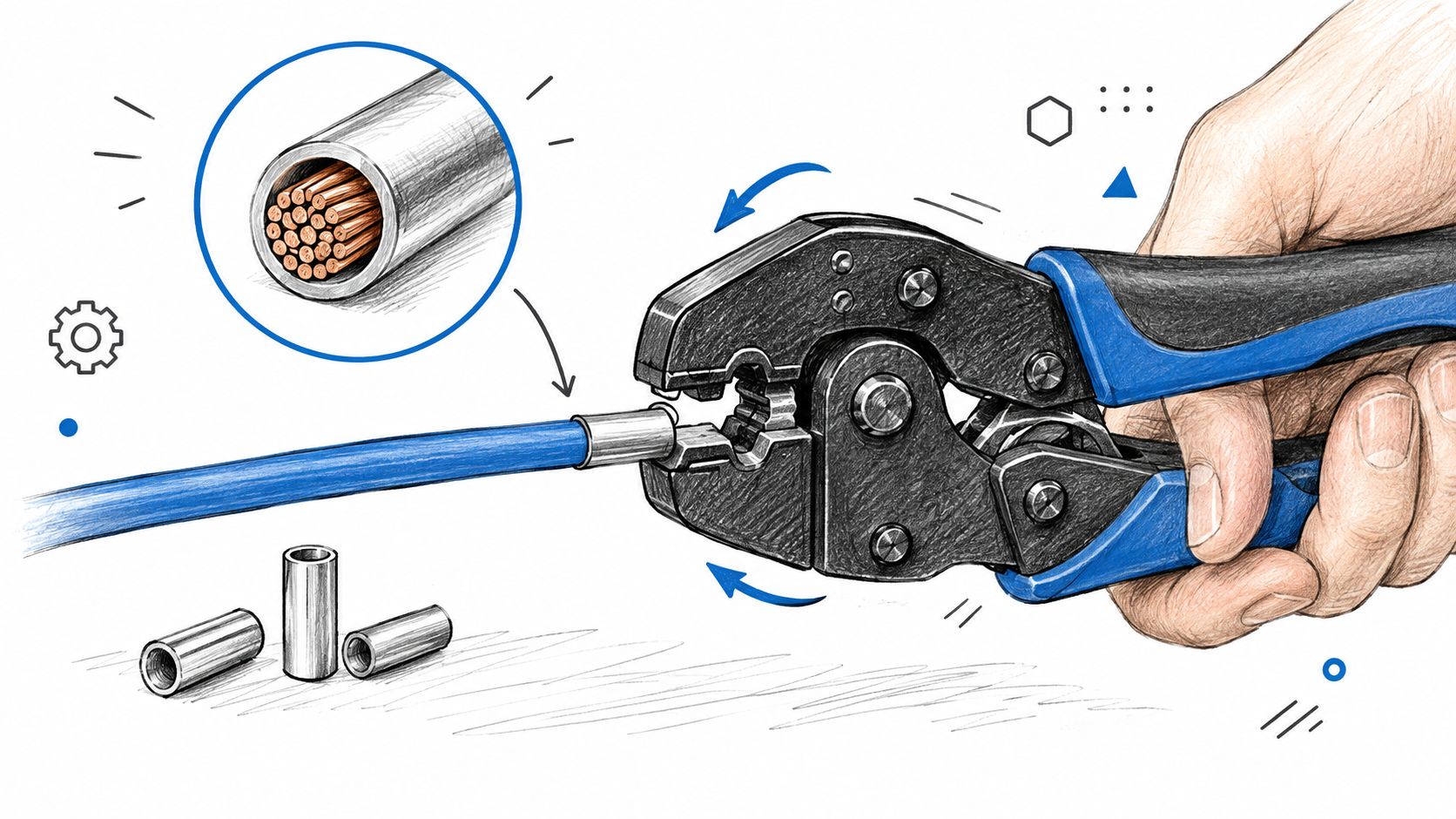
Insert the prepared conductor fully into the sleeve. Check the collar first. The insulation should approach the collar without being trapped beneath the metal barrel, and no stray strand should escape at the entry. If the conductor doesn't slide in straight, stop and correct the strip or ferrule selection before applying pressure.

A hand using a specialized crimping tool to secure a metal ferrule onto the end of a blue electrical cable.

Place the ferrule in the die with the collar facing the correct direction and the sleeve centered in the rated crimp zone. The die should land close to the sleeve shoulder without crushing the plastic collar. Keep the crimp axis aligned with the conductor. A rotated or off-axis indentation can leave one side compressed while another side remains loose.

Close the tool through its complete cycle. With a ratcheting tool, don't reopen the handles halfway through and call the result finished. The ratchet exists to prevent partial compression, and the final release confirms that the designed stroke has been completed.

Control the compression across the sleeve

For larger sleeves or tools designed for multiple compression points, follow the manufacturer's sequence from the rear zone toward the front. The sleeve needs continuous support along its working length, not a single deep mark that leaves the rest of the barrel loose. Keep successive indentations in the same plane and re-square the ferrule before each compression when the tool requires repositioning.

A finished profile may be square, trapezoidal, or multi-indent depending on the tool. The profile should be even, with no fish-mouth opening, copper flash, split sleeve, or damaged collar. The wire should exit straight rather than bending sharply at the sleeve edge.

The Phoenix Contact crimping test guidance describes a validation approach in which the ferrule remains fixed under a target tensile load before the pull continues to failure. That is the standard to keep in mind while crimping. A clean shape is useful evidence, but it isn't the acceptance test.

A practical video demonstration can help operators see tool positioning and complete-stroke technique:

Inspecting the Crimp Against Pull Force

A pull test answers the question visual inspection can't. Does the conductor remain fixed in the ferrule under axial load, or does it slide before the connection reaches its expected strength? Standards-based ferrule practice ties quality to dimensions, tensile performance, and reliable contact formation, not to a crimp that merely looks symmetrical.

Published Weidmüller crimp tables provide these minimum pull-force values for selected conductor sizes: 10 N at 0.5 mm², 40 N at 1.5 mm², 60 N at 4 mm², 80 N at 6 mm², 100 N at 16 mm², 135 N at 25 mm², and 190 N at 35 mm². These values appear in Weidmüller's crimping documentation. Don't interpolate a value for an unlisted size and treat it as an approved requirement. Use the ferrule and tool manufacturer's table for the exact combination.

Conductor Size Minimum Pull Force (N) Typical Failure Mode Below Threshold
0.5 mm² 10 Conductor slips from an under-compressed sleeve
1.5 mm² 40 Strand bundle moves inside the ferrule
4 mm² 60 Partial compression or oversized die leaves a loose joint
6 mm² 80 Sleeve deformation doesn't retain the conductor
16 mm² 100 Incomplete compression or poor die match
25 mm² 135 Large-conductor sleeve slips or fractures at the exit
35 mm² 190 Insufficient full-length compression or tool mismatch

Run the test as a controlled check

Clamp the ferrule or its test fixture without damaging the sleeve. Apply axial force with a pull gauge or load cell, hold the target load for the specified duration, and then continue at the prescribed rate until failure. The technical workflow described by Phoenix Contact holds the target load for 60 seconds and then increases the pull speed to about 25 mm/min. A passing connection remains fixed at the target load, while the conductor shouldn't pull out before the intended failure condition.

Visual inspection still matters. Check that the collar is intact, the indentation is symmetric, insulation isn't trapped beneath the barrel, and no copper has been shaved or pushed outside the sleeve. A crimp that looks excellent but falls below the applicable pull-force requirement is scrap.

NASA ultrasonic inspection research also shows why production teams shouldn't rely on appearance alone. One NASA study detected under-crimped terminations at a 97% detection rate, 93 of 96 samples, with a 1% false-call rate, 1 of 96, when ultrasonic transmission exceeded a threshold amplitude. The NASA report also connects ultrasonic amplitude changes with destructive pull-test outcomes. For routine bench work, calibrated tooling and destructive sampling may be sufficient. For higher-volume production, ultrasonic verification can add a non-destructive quality control layer.

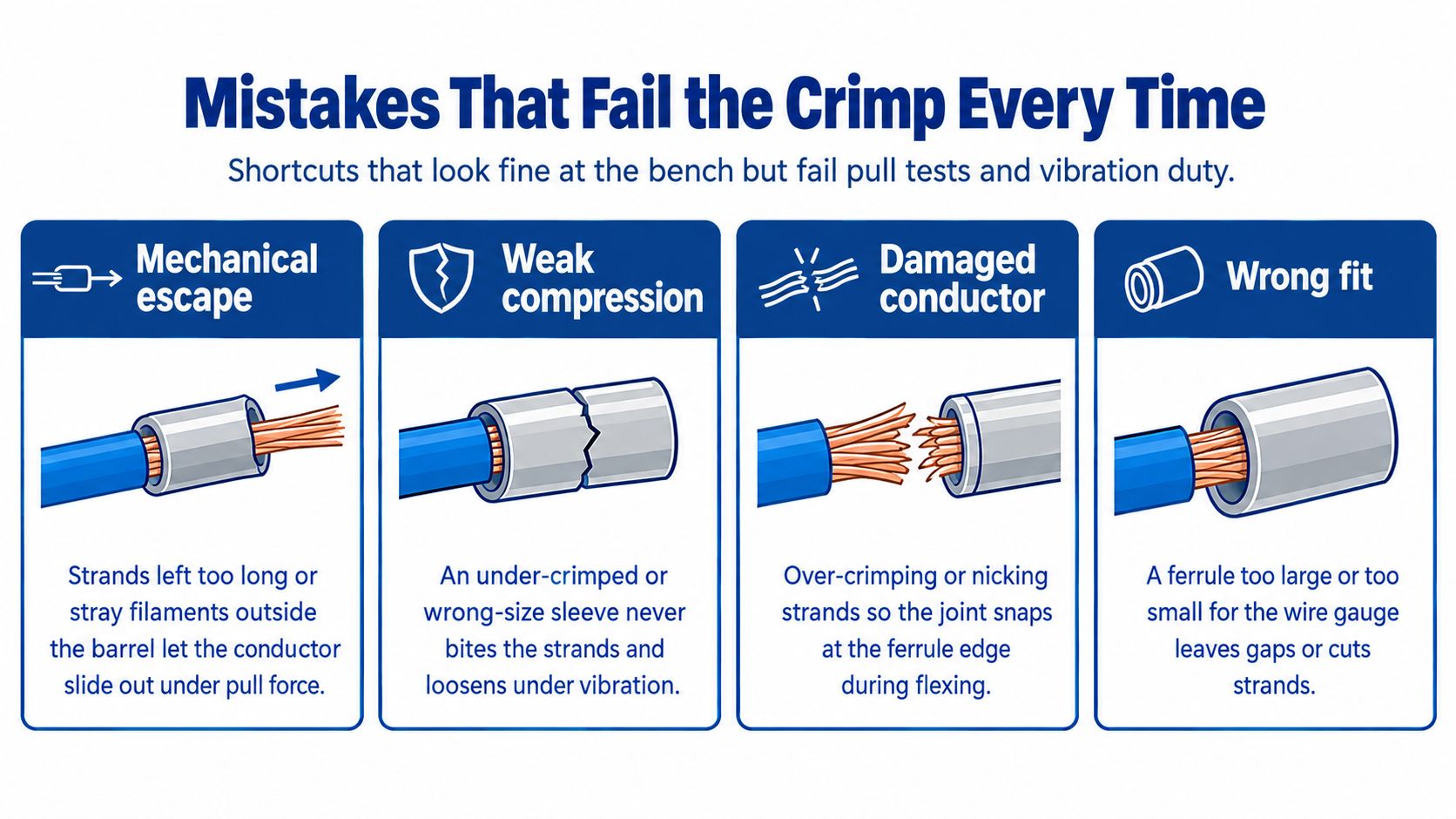
Mistakes That Fail the Crimp Every Time

The failures that cause trouble are usually small and repeatable. A wrong strip length, mismatched die, or incomplete tool stroke can produce a termination that passes a casual visual check while failing under pull or vibration.

An educational infographic illustrating four common crimping mistakes that lead to electrical connection failures.

Start with the mechanical escape paths

A short strip leaves a gap between the conductor end and the sleeve nose. That reduces the supported length and gives the strand bundle room to move. An excessively long strip exposes copper beyond the sleeve, which can interfere with terminal clearance and create an avoidable electrical hazard.

A mismatched die fails in two directions. An oversized die leaves the strands insufficiently compressed, while an undersized die can shave strands, crush the collar, or force copper out of the barrel. The correct die window is the one specified for the ferrule and conductor, not the closest opening that happens to accept the part.

Look for compression defects

Rotated indents, partial handle closure, and skipped compression zones leave gaps in the sleeve. Those gaps may allow movement and oxidation, increasing contact resistance over service life. A complete ratchet cycle and consistent die alignment remove much of that operator variation.

Tool condition matters just as much. Worn jaws, loose pivot pins, contamination in the die, or a ratchet mechanism that no longer completes its designed stroke can produce weak crimps even when the operator follows the sequence. Inspect the tool when a pull test fails. Replacing the ferrule without correcting the tool only repeats the defect.

Protect the conductor before it enters the sleeve

A dull stripper can nick strands. Insulation left under the barrel prevents the sleeve from gripping the intended copper length. Pre-tinned conductors bring solder creep and a rigid transition into a termination designed for flexible strands. Tinning isn't a substitute for a ferrule in a screw or spring terminal.

A two-wire shortcut isn't a standard termination. If two conductors need to enter one terminal, use a correctly specified twin ferrule and matching tool, or use an approved terminal arrangement.

A standard ferrule isn't a license to cram two wires into one sleeve. The barrel, collar, conductor combination, and tool must be designed for that configuration. If the terminal needs separate conductors, use separate ferrules or an approved bridging method. If the application calls for a ring, fork, or specialized connector, use that termination instead of forcing a ferrule into the wrong hardware.

When a Ferrule Is the Right Termination

The decision starts with the terminal, not the tool drawer. A ferrule is usually the right choice when a stranded conductor enters a screw or spring-clamp terminal rated for ferrules, especially where vibration, repeated service, or consistent insertion matters. The terminal manufacturer's instructions remain decisive because some terminals specify a particular ferrule profile, conductor class, or insertion length.

Ferrules are particularly useful for flexible control wiring and fine-stranded conductors because they contain the strands before clamping. They're also preferable to solder-tinning a stranded end. Tinning creates a rigid section that can fracture or deform under clamp pressure, while a correctly selected ferrule preserves a controlled mechanical termination.

Use the application as the decision filter

Do not add a ferrule automatically to every electrical connection. A ring or fork terminal is the proper choice for a stud or screw designed for that lug. A direct termination may be specified for a connector that doesn't accept ferrules. A PCB pigtail may need a connector or soldered joint designed for that board, not a ferrule selected from a panel-wiring kit.

Termination Method Best Application Standards Reference Key Limitation
Insulated ferrule Stranded conductor in an approved screw or spring terminal DIN 46228-1, EN 60999-1 Must match conductor size, terminal, and tool
Fine-stranded ferrule Flexible or fine-stranded conductor requiring controlled clamping DIN 46228-4, EN 60352-2 More sensitive to sleeve and tooling mismatch
Twin ferrule Two conductors entering a terminal approved for that arrangement Applicable ferrule and terminal manufacturer requirements Requires a correctly sized twin sleeve and die
Ring or fork terminal Stud, busbar, or screw connection designed for a lug Equipment and terminal requirements Not a substitute for a ferrule in a cage or spring terminal
Direct conductor termination Terminal specifically rated for the conductor without a sleeve Terminal manufacturer's instructions Strands can splay if the terminal isn't designed for them
Soldered pigtail Board or component connection designed for solder Product and assembly requirements Not a replacement for a ferrule under a clamping terminal

Standards guidance links ferrule quality to dimensions, test methods, and tensile performance. The Weidmüller ferrule reference is useful when translating that logic into a selection decision, but the equipment maker's terminal data should control the final choice.

For buyers, ATEK Distribution's wire termination and supplies can help consolidate ferrules, crimp tools, wire, and related termination products around a defined specification. Confirm the conductor cross-section, ferrule family, crimp profile, terminal model, and inspection requirement before placing a project-wide order.

A dependable cable ferrule crimp program is simple to state: match the sleeve, prepare clean copper, complete the correct die cycle, inspect the geometry, and verify pull performance against the applicable table. ATEK Distribution supplies electrical products and procurement support for contractors, industrial teams, facilities, utilities, and government buyers, including sourcing help for wire, cable, tools, and termination requirements. Visit ATEK Distribution to discuss the ferrules, crimping equipment, and project documentation your installation needs.

Guide to Types of Fuses

TECHNICAL GUIDE

Types of Fuses: A Complete Guide to Fuse Types, Ratings, Sizes and Selection

There is no official list of fuse types. Fuses are classified by physical form, by application, and by speed at once — which is why sources disagree on the number. A practical guide to the main families, what actually drives selection, and the ratings that matter.

ATEK Distribution · 10 September 2026 · 18 min read
Cartridge, blade, plug and glass fuses of different types arranged on a steel workbench

A fuse is a sacrificial overcurrent protection device: a calibrated metal element that melts and opens the circuit when current exceeds a safe level for long enough. There is no single official list of fuse types. Fuses are classified several different ways at once — by physical form (cartridge, blade, plug, glass), by application (branch circuit, supplemental, semiconductor, automotive), and by speed (fast-acting or time-delay). That is why one source says three types, another says five, and both can be right.

QUICK ANSWER

How many types of fuses are there? There is no fixed number. The count depends entirely on which classification system you are using.

By physical form, the common families are cartridge, blade, plug (screw-in), glass or small-dimension, and specialty types such as semiconductor and high-voltage fuses.

By application in the US, the distinction that carries legal weight is branch circuit versus supplemental. A supplemental fuse cannot be used as branch-circuit protection.

By speed, every family divides into fast-acting and time-delay.

Selection is never based on physical size. A fuse is chosen on current rating, voltage rating, interrupting rating, and time-current characteristic — then checked for physical fit.

What is a fuse?

Inside every fuse is a fuse element — a strip, wire or ribbon of metal sized so that it melts at a predictable current and time. Under normal load the element carries current with negligible heating. When current rises beyond the element’s design point, the metal heats, melts, and an arc forms across the gap. The fuse body extinguishes that arc and the circuit opens.

That mechanism explains two things people get wrong. A fuse is single-use — once it operates the element is gone, and replacing it with a larger one removes protection rather than restoring it. And a fuse that opens is doing its job. The useful question is never “why did the fuse blow” but “what caused the current.” A blown fuse is evidence of an overload, a short circuit, a ground fault or a failing motor. Fitting a bigger fuse hides the evidence and leaves the fault.

How many types of fuses are there?

Search for this and you will find pages confidently stating three types, four types, or five types. None of them is quoting a standard, because no standard defines a master list. Fuses are sorted along several independent axes, and each axis produces a different count.

Classification axis Typical categories What it tells you
Physical form Cartridge, blade, plug, glass/small-dimension, bolt-in Whether it fits your holder
Application / listing Branch circuit, supplemental, semiconductor, automotive Whether it is legal for the job
Speed Fast-acting, time-delay Whether it survives normal inrush
Voltage class Low-voltage, medium/high-voltage Which system it belongs in
Current-limiting behavior Current-limiting, non-current-limiting How much energy passes during a fault

The “five types” lists you see are usually describing physical form. The three-type lists usually collapse everything into cartridge, plug and blade. Neither is wrong. They are answering different questions.

For anyone actually specifying a fuse in the United States, the axis that matters most is not form. It is listing category, because that determines what the fuse is permitted to protect.

Branch circuit vs supplemental: the distinction that gets missed

Low-voltage fuses in North America are listed under the UL 248 standard series, with each category in its own part.

A branch circuit fuse is listed to protect branch-circuit conductors and equipment. Eaton’s Bussmann literature states the defining requirements plainly: a minimum interrupting rating of 10,000 A and a minimum voltage rating of 125 V, plus standardized rejection dimensions. These are the Class R, J, T, CC, L, G, H and K fuses.

A supplemental fuse is covered by UL 248-14, whose scope limits it to fuses “rated 60 A or less intended only for supplementary overcurrent protection where branch circuit or equivalent applications are not involved.” Most glass and small panel-mount fuses fall here, and a supplemental fuse cannot serve as the branch-circuit overcurrent device.

SIZE DOES NOT REVEAL LISTING CATEGORY

A midget-style fuse of identical dimensions may be supplemental or a Class CC branch-circuit fuse depending on how it is listed. The markings tell you; the shape does not.

The main fuse types

Type Typical use Form Notes
Cartridge Industrial, commercial, HVAC, motor circuits, disconnects Cylindrical ferrule or knife-blade The dominant branch-circuit format; organized by UL class
Blade Vehicles, boats, trailers, 12/24 V DC systems Flat plastic body, two spade terminals Color-coded by ampere rating; several size families
Plug (screw-in) Legacy residential panels Edison or Type S screw base 125 V, 30 A max; largely superseded by breakers
Glass / small-dimension Electronics, control circuits, appliances, instruments Glass or ceramic tube with metal end caps Usually supplemental, not branch-circuit rated
Semiconductor (high-speed) Drives, rectifiers, power electronics Usually bolt-in or specialized cartridge UL 248-13; explicitly not branch-circuit protection

Cartridge fuses

Cartridge fuses are the workhorse of commercial and industrial overcurrent protection. Two broad constructions dominate:

  • Ferrule type — metal caps at each end, gripped by spring clips. Common at lower ampere ratings, typically up to around 60 A depending on class.
  • Knife-blade type — flat blades extending from each end, clamped or bolted. Used at higher ampere ratings where a ferrule cannot carry the current or the mechanical load.

What separates one cartridge fuse from another is not the shape but the UL class. The class fixes the dimensions, the voltage rating, the interrupting rating, and the rejection features that prevent a lower-rated fuse from being installed in its place. Class R, J, T, CC, L, G, H and K each occupy their own part of UL 248.

Those classes carry real differences in protection — a Class H fuse and a Class J fuse of the same ampere rating are not equivalent devices. We cover the class-by-class detail, including why RK1 and RK5 are not interchangeable despite fitting the same holder, in our industrial fuse selection guide.

Blade fuses

Blade fuses are the standard for low-voltage DC systems in vehicles, boats and trailers. A colored plastic body carries the element between two flat blades that push into a socket.

They come in several size families — micro2, micro3, low-profile mini, mini, regular and maxi — and, importantly, they are not all governed by the same standard. SAE J1284 covers the regular (ATO/ATC) size; the mini format sits under SAE J2077 and the maxi under SAE J1888. Internationally, ISO 8820-3 covers blade-type fuse-links for road vehicles as Type C, E and F, rated 32 V or 58 V, up to 100 A, with a 1,000 A breaking capacity.

The color coding is genuinely standardized for the smaller families:

1 A
Black
2 A
Grey
3 A
Violet
4 A
Pink
5 A
Tan
7.5 A
Brown
10 A
Red
15 A
Blue
20 A
Yellow
25 A
Clear / natural
30 A
Green
40 A
Orange

Above 40 A the maxi family diverges from this map, and ISO 8820-3 itself assigns different colors to different type designations. Treat color as a quick visual check. The printed ampere rating on the fuse body is what counts.

Plug fuses

Plug fuses screw into a socket like a light bulb and belong to older residential and light commercial panels. The NEC treats them carefully because they were, historically, the easiest overcurrent device in the world to defeat.

  • 240.51 classifies Edison-base plug fuses at not over 125 volts and 30 amperes, and permits them only as replacements in existing installations where there is no evidence of overfusing or tampering.
  • 240.52 requires Edison-base fuseholders to be fitted with adapters that make them accept Type S fuses.
  • 240.53 covers Type S fuses: not over 125 volts, in three ampere classifications — 0–15 A, 16–20 A and 21–30 A — which are not interchangeable with one another.
  • 240.54 requires that a Type S adapter, once installed, cannot be removed.

The logic is straightforward. With an Edison base, any fuse fits any socket, so a 15 A fuse protecting 14 AWG wire can be swapped for a 30 A fuse by anyone with a spare in a drawer. Type S makes each ampere classification a different physical size, and the adapter locks the socket to it permanently.

NEC 240.50 adds the general rules: plug fuses are permitted on circuits not exceeding 125 volts between conductors, or on grounded-neutral systems where no conductor exceeds 150 volts to ground; fuses 15 A and below must be identifiable by a hexagonal window; and the screw shell must connect to the load side.

Glass and small-dimension fuses

Glass fuses protect electronics, control circuits, appliances and instruments. The transparent body is genuinely useful — you can often see whether the element is intact without pulling the fuse — though one that cleared a heavy fault may be blackened and unreadable.

Two form factors dominate, and they are not interchangeable:

  • US size: 1/4 inch × 1-1/4 inch, commonly sold as the 3AG family, which measures roughly 6.3 × 32 mm.
  • Metric / IEC size: 5 × 20 mm.

A common misconception is that UL and IEC are competing alternatives here. They are not — the same 5 × 20 mm fuse is routinely UL 248-14 Recognized and approved to EN/IEC 60127. UL 248-14 defines the listing category; IEC 60127 defines the dimensional and performance series.

Speed markings differ. US practice says fast-acting or time-delay; IEC 60127-1 uses letter codes — FF very quick acting, F quick acting, M medium time-lag, T time-lag, TT long time-lag.

NEVER SUBSTITUTE ON PHYSICAL FIT ALONE

Two glass fuses of identical length and diameter can differ in voltage rating, interrupting rating and speed. The holder will accept both. The circuit will not treat them the same.

Electrician comparing fuse markings against equipment documentation at a workbench

Fuse types and sizes: what actually determines selection

Physical size is the last thing you check, not the first. A fuse is defined by four electrical parameters plus its characteristic.

Parameter What it means What happens if it is wrong
Current rating The current the fuse carries continuously without opening Too low: nuisance operation. Too high: the circuit is unprotected
Voltage rating The maximum system voltage the fuse can safely interrupt The arc may not extinguish; the fuse can fail violently
Interrupting rating The maximum fault current the fuse can safely clear Rupture of the fuse and its holder under fault
Time-current characteristic How quickly it opens at a given overcurrent Fails to start motors, or fails to protect electronics
Physical format Dimensions, mounting, rejection features It does not fit, or the wrong class fits where it should not

Voltage rating is the one non-electricians misread most often. A fuse may be applied at or below its voltage rating, never above. A 250 V fuse does not belong in a 480 V circuit no matter how well the ampere rating matches.

Interrupting rating is the one professionals overlook in legacy equipment. NEC 110.9 requires equipment intended to interrupt current at fault levels to have an interrupting rating at least equal to the current available at its line terminals. NEC 240.60(C) requires fuses to be marked with ampere rating, voltage rating, interrupting rating where other than 10,000 amperes, current-limiting designation where applicable, and the manufacturer’s name or trademark — which means a fuse with no interrupting rating marked on it is a 10,000 A fuse. Available fault current at many modern services is well beyond that.

The 2026 edition expanded the related equipment marking obligations, including field marking of available fault current. We cover those changes in our guide to the 2026 NEC arc flash labeling requirements.

Fuse rating formula and selection calculation

There is no single equation that selects a fuse for every system. Anyone presenting one is oversimplifying. What does exist is a sequence: calculate the load, apply the code rules for the circuit type, then check the fuse against the conductor and the equipment.

1

Calculate load current

From power and voltage:

  • Single-phase: I = P ÷ V
  • Single-phase with power factor: I = P ÷ (V × PF)
  • Three-phase: I = P ÷ (√3 × V × PF)

For motors, do not calculate from nameplate horsepower. Use the applicable NEC full-load current tables, which is what the code sizing rules are written against.

2

Apply the continuous load rule

NEC 210.20(A) for branch circuits and 215.3 for feeders require the overcurrent device rating to be not less than the noncontinuous load plus 125 percent of the continuous load. A continuous load is one expected to run for three hours or more. An exception applies where the assembly, including the overcurrent devices, is listed for operation at 100 percent of its rating.

You will also see the reciprocal guidance that fuses should not be loaded above 80 percent of rating continuously. Both express the same relationship — 100 A × 1.25 = 125 A, and 100 A is 80 percent of 125 A — and the reason is heat inside an enclosure, not weakness in the fuse element.

Manufacturers frame it differently and both positions are worth knowing. Mersen states that continuous load should not exceed 80 percent of fuse ampere rating, excepting Class L and E-rated fuses. Eaton argues the limitation is the switch and terminations rather than the fuse, noting UL-listed fuses 600 A and below undergo a 100 percent test. Either way the installation is governed by the NEC rules above, and any 100 percent application requires a listed assembly.

3

Select a standard rating

NEC 240.6(A) sets the standard ampere ratings: 15, 20, 25, 30, 35, 40, 45, 50, 60, 70, 80, 90, 100, 110, 125, 150, 175, 200, 225, 250, 300, 350, 400, 450, 500, 600, 700, 800, 1000, 1200, 1600, 2000, 2500, 3000, 4000, 5000 and 6000 amperes — plus, for fuses only, 1, 3, 6, 10 and 601 amperes. That fuse-only addition is routinely omitted from online summaries.

4

Check the conductor

NEC 240.4 requires conductors to be protected in accordance with their ampacities. Two provisions come up constantly:

  • 240.4(B) permits the next higher standard device rating where the conductor ampacity does not match a standard rating, subject to conditions — including that the circuit does not supply more than one receptacle for cord-and-plug-connected portable loads, and that the next higher rating does not exceed 800 amperes.
  • 240.4(D) limits small conductors after applying correction and adjustment factors: 15 A for 14 AWG copper, 20 A for 12 AWG copper, 30 A for 10 AWG copper, 15 A for 12 AWG aluminum and 25 A for 10 AWG aluminum. Note that 240.4(D) is subject to the exceptions in 240.4(E) and 240.4(G), which cover tap conductors, motor circuits, air-conditioning equipment and more.
5

Account for inrush

Motors, transformers and other inductive loads draw heavy starting current. A fast-acting fuse sized for running current will open on every start. For motor branch circuits, NEC Table 430.52 sets maximum sizing for AC polyphase squirrel-cage motors at 300 percent of full-load current for non-time-delay fuses and 175 percent for dual-element time-delay fuses.

Those percentages size the device for short-circuit and ground-fault protection. Motor overload protection is a separate requirement and a separate device.

6

Verify voltage, interrupting rating and fit

Confirm the fuse voltage rating is at or above system voltage, that the interrupting rating covers available fault current per 110.9, and only then check that the fuse physically fits the holder and that the holder’s rejection features match the class you specified.

WORK FROM YOUR ADOPTED EDITION

Code citations here are given by article number because adopted editions vary by state. Minnesota moved to the 2026 NEC in August 2026, while many states remain on earlier editions — always work from the edition your jurisdiction has adopted.

Fast-acting vs time-delay fuses

  Fast-acting Time-delay
Behavior on overload Opens quickly Tolerates a temporary overload before opening
Suits Resistive and non-inductive loads: heaters, lighting, ovens; sensitive electronics Motors, transformers, capacitive and inductive loads with startup inrush
Construction Single element Often dual-element
Failure mode if misapplied Nuisance opening on every motor start Slow response where fast clearing was needed

Swapping one characteristic for the other because it was what the parts drawer held is a common and consequential mistake. A time-delay fuse in a circuit that needed fast clearing lets more energy through before the fault is interrupted.

Semiconductor and drive circuits need a further step again. High-speed fuses covered by UL 248-13 are selected by matching let-through I²t against the semiconductor’s I²t withstand rating, and per Eaton’s technical literature they are not considered branch circuit protection under the NEC. A general-purpose fast-acting fuse is not a substitute.

Types of fuses for home use

Most US homes built or rewired in recent decades use circuit breakers rather than fuses. Fuse panels still exist in older housing stock, and they are not automatically unsafe — a properly fused panel in good condition protects a circuit perfectly well.

Where fuses remain, you will typically find:

  • Plug fuses in Edison or Type S bases, protecting 120 V lighting and receptacle circuits at 15, 20 or 30 A.
  • Cartridge fuses in pull-out blocks for 240 V circuits such as ranges, dryers and the main disconnect.
  • Small glass or supplemental fuses inside appliances and equipment, which are not branch-circuit protection.

Two points matter most. Never install a fuse rated higher than the circuit was designed for — the wiring, not the fuse, sets the limit, and overfusing is exactly the hazard Type S was created to prevent. And treat a repeatedly blowing fuse as a fault to diagnose, not a fuse to upsize.

WHO SHOULD DO THIS WORK

Work inside a panel, and any modification to fixed wiring, belongs to a licensed electrician. Replacing a plug fuse of the same rating is a homeowner task; anything beyond that is not.

Fuse holders

A fuse holder retains the fuse and connects it into the circuit. It carries the same current as the fuse, must be rated for the same voltage, and its rejection features are what prevent the wrong class being fitted later.

  • Panel-mount holders — screw or bayonet holders for glass and small-dimension fuses in equipment.
  • Fuse blocks and clips — DIN-rail or panel-mounted bases for cartridge fuses in control panels and distribution equipment.
  • Inline holders — a fuse carrier spliced into a conductor run, common in DC and automotive work.
  • ANL and high-current holders — bolt-down bases for large DC loads.
  • Fused disconnects and switches — combining a switching means with cartridge fuse mounting for branch-circuit and feeder protection.

Three rules apply regardless of type: the holder’s ratings must equal or exceed the fuse’s; it must accept the class you specified (a Class R rejection holder will not take a Class H fuse, deliberately); and terminations must be sized and torqued for the conductor, because a loose clip generates heat that will eventually open a perfectly good fuse.

Fused disconnect switch and fuse blocks inside an industrial control panel

Fuse installation: the safety essentials

General guidance, not an installation procedure. Fixed wiring, panels and mains-voltage work belong to qualified electrical professionals working to the code adopted in your jurisdiction.

  • De-energize first. Isolate the circuit, follow lockout/tagout where applicable, and verify absence of voltage with a tester you have proven on a known live source.
  • Replace like with like. Same ampere rating, same voltage rating, same interrupting rating, same class, same speed characteristic.
  • Investigate before replacing. A fuse that opened was responding to something.
  • Match the holder. Use a holder rated for the fuse and the circuit, with terminations sized for the conductor.
  • Position inline protection close to the source. An inline fuse protects the conductor downstream of it; the length of unprotected cable upstream is exposed.
  • Follow the manufacturer’s instructions. Listed equipment must be installed as listed.

Common fuse selection mistakes

Choosing on ampere rating alone and ignoring voltage, interrupting rating and characteristic.
Assuming identical size means identical specification. It frequently does not.
Fitting a higher-rated fuse to stop repeat operation, which removes protection instead of finding the fault.
Using a supplemental fuse as branch-circuit protection — not permitted, regardless of physical fit.
Ignoring available fault current and leaving a 10,000 A fuse in a service that exceeds it.
Swapping time-delay for fast-acting or the reverse because of what was in stock.
Overlooking ambient temperature, which shifts performance in hot enclosures and outdoor equipment.
Sizing without checking conductor ampacity under NEC 240.4.
Defeating a holder’s rejection feature to make a fuse fit.

How to choose the right fuse

A working sequence, in order:

  1. Application — what is being protected, and is this branch-circuit, supplemental or specialty duty?
  2. Load — calculate current; identify continuous versus noncontinuous.
  3. Voltage and AC/DC — a DC rating is not implied by an AC rating.
  4. Inrush — does the load start hard?
  5. Conductor — check ampacity and small-conductor limits.
  6. Interrupting rating — from a short-circuit study or the utility, not an assumption.
  7. Characteristic — fast-acting, time-delay, or semiconductor-rated.
  8. Class and format — which UL class, which physical size, which rejection feature.
  9. Holder compatibility — rated to match, and matching the class.
  10. Code and manufacturer requirements — the adopted NEC edition and the equipment listing.

Frequently asked questions

What are the 5 types of fuses?

When a source lists five types of fuses it is usually describing physical form: cartridge, blade, plug (screw-in), glass or small-dimension, and specialty types such as semiconductor or high-voltage fuses. No standard fixes that number at five. Fuses are also classified by application, speed, voltage class and current-limiting behavior, and each of those produces a different count.

What are the 3 types of fuses?

Three-type lists typically mean cartridge, plug and blade fuses — the three most recognizable physical formats. It is a reasonable simplification for a general audience, but it leaves out glass and supplemental fuses in electronics and specialty types such as semiconductor fuses, so it is not a complete picture for anyone specifying protection.

How many types of fuses are there?

There is no fixed number, because fuses are classified along several independent axes at once. By physical form there are roughly five common families. By UL listing category in North America there are more than a dozen, since UL 248 devotes a separate part to each fuse class. By speed there are two. The useful question is not how many types exist but which classification matters for the job in front of you.

What is a cartridge fuse?

A cartridge fuse is a cylindrical fuse with contacts at each end — either ferrule caps gripped by clips, or flat knife blades that clamp or bolt in. Cartridge fuses are the standard format for branch-circuit and feeder protection in commercial and industrial systems, and they are organized by UL class (R, J, T, CC, L, G, H, K), which fixes their dimensions, voltage rating, interrupting rating and rejection features.

What are glass fuse types?

Glass fuses are small cartridge fuses with a transparent body, used in electronics, appliances, instruments and control circuits. Two dimensional families dominate: the US 1/4 inch × 1-1/4 inch size (the 3AG family, about 6.3 × 32 mm) and the metric 5 × 20 mm size. Each comes in fast-acting and time-delay versions, and most are supplemental fuses under UL 248-14 rather than branch-circuit fuses.

What is the fuse rating formula?

There is no single universal formula. Load current is calculated as I = P ÷ V for single-phase, or I = P ÷ (√3 × V × PF) for three-phase. The fuse is then sized according to the applicable code rules — for example, NEC 210.20(A) requires the overcurrent device to be rated at not less than the noncontinuous load plus 125 percent of the continuous load — and checked against conductor ampacity, inrush requirements, voltage rating and interrupting rating.

Can I replace a fuse with a higher amp rating?

No. The fuse rating is set by the conductor and equipment it protects, not by how often the fuse operates. Fitting a higher-rated fuse allows more current through wiring that was never sized for it, which is a fire risk, and it removes the evidence of whatever fault caused the original operation. A fuse that keeps opening is reporting a problem that needs diagnosis.

What is the difference between fast-acting and time-delay fuses?

A fast-acting fuse opens quickly on overcurrent and suits resistive loads and sensitive electronics. A time-delay fuse tolerates a brief overload before opening, which lets motors and transformers start without nuisance operation while still protecting against sustained overload and short circuit. Substituting one for the other changes the protection even when the ampere rating and physical size match.

How does a fuse holder work?

A fuse holder mechanically retains the fuse and connects it into the circuit through spring clips, screw terminals or bolted connections, carrying the same current as the fuse itself. It must be rated for at least the circuit’s voltage and current, and its rejection features are what stop an incorrect fuse class being fitted later. A loose or corroded holder generates heat and can cause a correctly sized fuse to open.

What interrupting rating does a fuse need?

NEC 110.9 requires equipment intended to interrupt fault current to have an interrupting rating at least equal to the current available at its line terminals — a figure that comes from a short-circuit study or the utility, not an estimate. NEC 240.60(C) requires the interrupting rating to be marked only where it differs from 10,000 amperes, which means an unmarked fuse is a 10,000 A device.

Is HRC a type of fuse?

HRC, meaning high rupturing capacity, is British and IEC terminology and a formal classification in Canada under CSA C22.2 No. 106. It is not a term used by the NEC or UL 248. The equivalent US concept is a current-limiting fuse, identified in practice by its UL class — J, R, L, T, CC or G — which carries the interrupting rating and current-limiting performance.

Are fuses better than circuit breakers?

Neither is universally better. Fuses are single-use, generally offer very fast current-limiting performance, and cannot be reset or defeated once correctly specified. Breakers are resettable, provide a switching means, and are easier to restore after a trip. Modern residential and most commercial construction uses breakers; fuses remain standard for many industrial, motor and semiconductor applications where their clearing characteristics are an advantage.

Getting the right fuse for your application

Most fuse problems are specification problems, not product problems. The fuse that fits is not always the fuse that protects, and the difference usually comes down to class, characteristic and interrupting rating rather than ampere rating.

ATEK Distribution is an SDVOSB-certified electrical distributor and GSA contract holder based in Minneapolis, supplying fuses, fuse blocks and fuse holders alongside circuit breakers, power distribution equipment and wire and cable to contractors, industrial facilities and government buyers nationwide.

Send the application details — voltage, current, load type, equipment nameplate, and a photograph of the existing fuse and holder if you have one.

Sources and technical references

This guide is general reference information for specification and procurement planning. It is not a substitute for the National Electrical Code as adopted in your jurisdiction, a short-circuit or coordination study, the equipment manufacturer’s instructions, or the judgment of a qualified electrical professional. Verify all ratings against the manufacturer’s current datasheet for the specific part before installation.

Minnesota Has Adopted the 2026 NEC: What Changed and What It Costs You

CODE UPDATE

Minnesota Has Adopted the 2026 NEC: What Changed and What It Costs You

A procurement-focused read of the changes that alter what you specify, order and install — not the full 700-page revision.

ATEK Distribution  ·  Published 4 September 2026  ·  7 min read
Electrical code reference book, dielectric gloves and multimeter on a workbench

Minnesota moved to the 2026 National Electrical Code on 17 August 2026. Permits pulled before that date follow the 2023 NEC; permits after it follow the 2026 edition. Minnesota licensing exams switch to the 2026 NEC on 8 September 2026.

If you are pulling permits in Minnesota this month, you are already working under a code that most of the country has not adopted yet. This guide covers the changes that affect what you specify, order and install — not the full 700-page revision, but the parts that change a purchase order.

The dates that matter

ISSUED
20 August 2025
2026 NEC issued
The NFPA Standards Council issued the 2026 NEC, superseding the 2023 edition.
IN EFFECT
17 August 2026
Minnesota adoption effective
Permits issued before this date follow the 2023 NEC. Permits issued on or after it follow the 2026 NEC.
NEXT MILESTONE
8 September 2026
Licensing exams switch
Minnesota electrical licensing examinations begin testing on the 2026 NEC.

READ THE STATE RULE, NOT THIS SUMMARY

Minnesota adopts the NEC through Minnesota Rules Chapter 1315, and the state’s rulemaking record confirms adoption “with any Minnesota amendments.” Those state-specific amendments are not reproduced in this article. Minnesota amendments are exactly the detail an inspector will hold you to, and we are not going to paraphrase them second-hand — get the adopted rule text from the Department of Labor and Industry or contact the Board of Electricity directly.

The four changes most likely to change what you order

1

Arc flash labels are now required on nearly all commercial and industrial equipment

Section 110.16 previously tied expanded arc flash labelling to equipment rated 1,000 A and above. The 2026 edition removes that threshold for non-dwelling installations. Switchboards, switchgear, enclosed panelboards, industrial control panels, meter socket enclosures and motor control centres in commercial and industrial occupancies now fall in scope.

The label content expanded too. Documented requirements include nominal system voltage, the arc flash boundary, available incident energy or the required PPE level, and the date the arc flash assessment was determined — bringing the NEC into line with NFPA 70E.

What this means on site: a label without an assessment date behind it is not a compliant label. This is a study-and-documentation requirement wearing a labelling requirement’s clothes.

We have covered the labelling changes in detail in the 2026 NEC’s expanded arc flash and fault-current marking requirements.

Electrical code reference book, dielectric gloves and multimeter on a workbench
2

Available fault current must be field-marked on switchboards and panelboards

New section 408.6 requires field marking of the available fault current and the short-circuit current rating on switchboards and panelboards in non-dwelling installations.

That figure has to come from somewhere — a short-circuit study, or the utility. It is also the number that determines whether the overcurrent devices in the enclosure are legal under 110.9. Plenty of existing gear carries devices sized for a fault current nobody has recalculated since the service was upgraded.

3

Cable ties used for support must be listed for the purpose

New section 300.13 requires that cable ties used for securement and support be listed and identified for that use.

This is the change most likely to catch a job out on a technicality, because generic ties are everywhere and cost almost nothing. If your standing order includes bulk cable ties for support applications, that line needs checking against the listing rather than the price.

Gloved hands securing bundled cable to a cable tray with a listed cable tie
4

Receptacles used for EV charging must be listed for EVSE use

Section 625.44 requires that 30 A, 50 A and 60 A receptacles used for electric vehicle charging be listed for EVSE use. An ordinary receptacle of the same rating no longer satisfies the requirement.

Article 625 changed substantially in other ways as well — including a new emergency shutoff requirement for non-dwelling installations. We have covered those separately in EV charging under the 2026 NEC.

Structural changes that will break your bookmarks

The 2026 edition reorganised several article numbers. If you cite code sections in submittals, specifications or training material, these need updating:

Was Now Subject
Article 220 Article 120 Branch-circuit, feeder and service load calculations
Article 750 Article 130 Energy management systems
Article 235 Articles 265–270 Medium-voltage branch circuits, feeders, services and grounding, split across five new articles

Medium-voltage requirements were restructured more broadly, with over-1000-volt content consolidated into dedicated articles rather than scattered through the general chapters.

Other changes worth knowing

300.4
Damaged conductors must be replaced
Conductors and wiring methods that are overheated, fire-damaged or water-damaged must be replaced. Previously a judgement call, now explicit.
110.26
Working space clarified
Obstruction of access and egress is now assessed with equipment doors open at 90 degrees, which is the realistic worst case rather than the convenient one.
110.3(B)
Manufacturer instructions
Installation instructions may exceed Code requirements but cannot reduce them. A new informational note addresses cybersecurity for network-connected equipment.
230.70(A)
Service disconnect location
For one- and two-family dwellings, the service disconnect must be outdoors, on or within sight of the dwelling. Remote-control devices are explicitly prohibited as the service disconnecting means.
GFCI
New device classifications
The traditional GFCI is now formally a Class A device, and new special-purpose classes have been introduced along with high-frequency-tolerant types intended to address nuisance tripping around drives and inverters. Compliance dates vary by provision; check the code text for the specific application rather than relying on a summary.

What a distributor can actually help with

Code adoption creates three procurement problems, and they arrive in this order.

01
No longer compliant for a given use
EVSE-listed receptacles and listed cable ties are the clearest examples in this cycle. The part still exists and still works; it is the application that changed. Standing orders and stock lists written under the 2023 NEC need reviewing line by line.
02
Now required and were not before
Arc flash and fault-current labelling on equipment that previously fell below the threshold. Surge protection scope expanded in several occupancy types.
03
Documentation
Listings, cut sheets and ratings are what an inspector accepts. Assembling them after delivery, from packaging, is avoidable work.

Quoting against the 2026 NEC

ATEK Distribution supplies power distribution equipment, circuit breakers, industrial safety equipment and wire, cable and cable support to contractors, facilities and government buyers from Minneapolis. Send a list or a takeoff and we will quote against it with ratings and listings stated per line.

Frequently asked questions

When did Minnesota adopt the 2026 NEC?

Minnesota’s 2026 NEC adoption took effect on 17 August 2026. According to the Minnesota Department of Labor and Industry, permits issued before that date are governed by the 2023 NEC, and permits issued on or after it are governed by the 2026 NEC. Minnesota adopts the code through Minnesota Rules Chapter 1315, with state amendments.

When do Minnesota electrical licensing exams switch to the 2026 NEC?

Minnesota electrical licensing examinations begin testing on the 2026 NEC on 8 September 2026. Candidates sitting exams on or after that date should be studying the 2026 edition.

What is the biggest 2026 NEC change for commercial buildings?

For commercial and industrial work, the expansion of arc flash labelling under 110.16 is the change with the broadest reach. The previous 1,000 A threshold was removed for non-dwelling installations, so switchboards, switchgear, enclosed panelboards, industrial control panels and motor control centres now require labelling that includes the date the arc flash assessment was determined. Alongside it, new section 408.6 requires field marking of available fault current and short-circuit current rating on switchboards and panelboards.

Does the 2026 NEC change what receptacles can be used for EV charging?

Yes. Section 625.44 requires that 30 A, 50 A and 60 A receptacles used for EV charging be listed for EVSE use. A standard receptacle of the same ampere rating no longer satisfies the requirement, which affects both new installations and replacement parts.

Where can I find Minnesota’s amendments to the 2026 NEC?

Minnesota adopts the NEC with state amendments through Minnesota Rules Chapter 1315. The adopted rule text and current guidance are published by the Minnesota Department of Labor and Industry. Because amendments are what local inspectors enforce, work from the state’s own published rule rather than from a summary — including this one.

Which edition of the NEC applies to a job that started before 17 August?

The Minnesota Department of Labor and Industry ties the applicable edition to the permit. Permits issued before 17 August 2026 follow the 2023 NEC; permits issued on or after that date follow the 2026 NEC. On long-running projects this means two editions can apply across different phases, so confirm the permit date rather than assuming the current code applies to everything on site.

Sources. NFPA 70 (2026) issuance confirmed via UL Solutions and the Massachusetts electrical code regulation. Minnesota dates from the Minnesota Department of Labor and Industry. Code change summaries from EC&M and IAEI. This article is a summary for procurement planning, not a substitute for the code text, the state amendments, or the authority having jurisdiction.

Industrial Fuse Selection Guide: Classes, Ratings and How to Specify the Right Fuse

Choosing an industrial fuse comes down to four things, in this order: voltage rating, ampere rating, interrupting rating, and fuse class. Get the first three wrong and the fuse is unsafe. Get the class wrong and it will physically fit, pass inspection, and quietly protect less than the fuse it replaced.

That last failure is the common one. A Class R fuseholder accepts both RK1 and RK5 fuses. They are the same size, carry the same voltage and ampere markings, and cost differently enough that substitution happens on availability rather than on specification. The equipment still runs. The protection is not the same.

This guide covers the low-voltage fuse classes defined under the UL 248 standard series, what separates them, what the markings legally mean, and what to confirm before you order a replacement. It is written for people specifying and buying fuses for commercial and industrial equipment. If you are trying to understand fuses in general — the physical families, home fuse boxes, blade fuses, how a fuse works — start with our broader guide to types of fuses and come back here when you need the specification detail.

Quick answer

  • Four ratings decide the fuse: voltage, ampere, interrupting rating, and class. The class is last, not first.
  • Class H is the one to watch. It is rated 10,000 A interrupting and it is not current-limiting. Modern services routinely exceed that.
  • RK1 and RK5 both fit the same holder and both carry 200 kA. RK1 lets through less energy. Substituting changes the protection without changing the fit.
  • Class K is current-limiting but is not allowed to be marked "current limiting" — because it has no rejection feature. This is the single most misreported fact in fuse selection.
  • Rejection features exist to keep the wrong fuse out. Classes R, J, T, CC, CD, CF and G have them. Classes H, K and L do not.
  • Sizing for motors is about dual-element construction, not class. A dual-element time-delay fuse sizes at roughly 125–150% of motor full-load current; a single-element fuse may need 300% just to survive starting.

Start with the three ratings, before the class

Fuse class describes a body style and a performance envelope. It does not replace the three ratings that determine whether the fuse is legal and safe in the circuit.

  • Voltage rating. A fuse may be applied at or below its voltage rating, never above. A 250 V fuse does not belong in a 480 V circuit, regardless of ampere rating.
  • Ampere rating. Set by the conductor, the load, and the applicable NEC article — not by what was in the holder when you opened the panel.
  • Interrupting rating. The fault current the fuse can safely clear. NEC 110.9 requires overcurrent devices intended to interrupt fault current to have an interrupting rating at least equal to the fault current available at their line terminals.

Interrupting rating is where legacy equipment causes problems. Class H fuses carry a 10,000 A interrupting rating. Available fault current at a modern service can be several times that. A Class H fuse left in place through a service upgrade is a code violation that nothing on the panel will announce.

Low-voltage fuse classes compared

All figures below are the class definitions under UL 248. Individual manufacturers publish higher interrupting ratings on some lines — 300 kA is common on Class J, L and R product — so confirm against the datasheet for the part you are actually buying.

ClassAmpere rangeVoltageInterrupting ratingRejectionCurrent-limitingUL 248 part
Hup to 600 A250 / 600 V10 kANoNo248-6, 248-7
K (K1, K5, K9)up to 600 A250 / 600 V50 / 100 / 200 kANoYes, but may not be marked248-9
R (RK1, RK5)up to 600 A250 / 600 V200 kAYesYes248-12
Jup to 600 A600 V200 kAYesYes248-8
Tup to 1200 A300 / 600 V200 kAYesYes (high degree)248-15
CCup to 30 A600 V200 kAYesYes248-4
CD35–60 A600 V200 kAYesYes248-18
CFup to 400 A600 V ac / 300 V dc300 kA to 100 A; 200 kA aboveYesYes248-17 (Outline)
Gup to 60 A600 V to 20 A; 480 V, 25–60 A100 kAYes (by length)Yes248-5
L601–6000 A600 V200 kANoYes248-10

Classes H and K share dimensions and are interchangeable in the same holders. That is precisely the problem with them: nothing physically stops a 10 kA Class H fuse going into a holder that was carrying a 200 kA Class K fuse. Classes R, J, T, CC, CD, CF and G all carry rejection features that prevent a lower-rated fuse being installed in their place.

Class L is the exception at the top end. It is bolt-in construction and its dimensions vary with ampere rating, so it has no defined rejection element in the way Class R or J does — the physical mounting is what constrains the fit.

What "current limiting" actually means, and why Class K cannot say it

A current-limiting fuse clears a fault in less than half a cycle, so the prospective peak current is never reached. The NEC definition is a device that, when interrupting currents in its current-limiting range, reduces the current in the faulted circuit to a magnitude substantially less than would flow if the device were replaced by a solid conductor of comparable impedance.

Manufacturer-published figures show the size of the effect. Mersen gives an example where 35,000 A rms available fault current — which would otherwise produce an 80,500 A peak — is limited by a 200 A Class J fuse to 12,000 A peak let-through. Eaton's cable-whip demonstration shows a 200 A fuse limiting peak current to 10.2 kA against 48.1 kA unlimited.

Here is the fact that most fuse guides get wrong. Class K fuses are current-limiting in performance — K1 to a high degree, K5 to a moderate degree. But they are not permitted to carry the "Current Limiting" marking, because NEC 240.60(B) requires that fuseholders for current-limiting fuses reject fuses that are not current-limiting. A Class K fuse fits an unmodified Class H holder, so allowing the marking would defeat the rule the marking exists to support.

Class H is the class that genuinely is not current-limiting. If you read a page that says "Class K is not current-limiting," it has confused the marking rule with the physics.

What the label has to tell you

NEC 240.60(C) requires cartridge fuses and fuseholders to be plainly marked with the ampere rating, the voltage rating, the interrupting rating where it is other than 10,000 A, the words "current limiting" where applicable, and the manufacturer's name or trademark. Manufacturers additionally mark the UL/CSA class.

That class marking is how you know the fuse is branch-circuit rated at all. A fuse with no UL class designation is a supplemental fuse under UL 248-14, and a supplemental fuse cannot be used as branch-circuit protection. It is intended to protect a component inside a listed assembly, downstream of something that already provides branch-circuit protection.

RK1 vs RK5: the substitution worth understanding

RK1 and RK5 are both Class R. Both are 200 kA. Both fit the same rejection holder. The difference is how much energy they let through while clearing a fault.

RK1 fuses are more current-limiting than RK5. They clear faster under high fault current, producing lower peak let-through current and lower let-through energy. RK5 fuses let more energy through before the fault clears.

That matters in three places:

  • Equipment short-circuit current ratings. A series-rated or component-protected assembly may have been evaluated with a specific fuse class. Substituting a less current-limiting fuse can invalidate the rating the assembly was labelled with.
  • Arc-flash studies. Incident energy calculations depend on the clearing characteristics of the device. Change the device, and the study no longer describes the installation the labels are attached to. We cover this in more detail in our guide to the 2026 NEC arc flash labeling requirements.
  • Selective coordination. Where the design required upstream and downstream devices to coordinate, the time-current curves were chosen deliberately. A substitution changes the curve.

If the equipment label or the drawing specifies RK1, order RK1. If nobody knows why the original was RK1, that is a question for the engineer of record before it is a purchasing decision.

Class R fuse dimensions

Class R dimensions are set by the standard, so they are the same across manufacturers for a given voltage and ampere band. The table below is from Littelfuse FLSR (600 V) and FLNR (250 V) datasheets and applies to Class H, K and R bodies alike.

Ampere range600 V length × diameter250 V length × diameter
up to 30 A5.00 in × 0.76 in2.00 in × 0.50 in
35–60 A5.50 in × 1.00 in3.00 in × 0.76 in
70–100 A7.88 in × 1.24 in5.88 in × 1.00 in
110–200 A9.63 in × 1.74 in7.13 in × 1.50 in
225–400 A11.63 in × 2.50 in8.63 in × 2.00 in
450–600 A13.38 in × 3.00 in10.38 in × 2.50 in

Note what that table shows: a 30 A Class R fuse is 5.00 inches long at 600 V and 2.00 inches at 250 V. The voltage rating changes the physical size, so 250 V and 600 V Class R fuses cannot be interchanged even before the rejection groove is considered. If you are measuring a fuse to identify it, measure length and diameter together and note the voltage marking.

Time-delay and fast-acting: match the fuse to the load

Time-delay fuses tolerate a temporary overload before opening. Fast-acting fuses do not. The choice follows the load, not preference.

  • Motors, transformers and other inductive loads draw high inrush at start. A fast-acting fuse sized for running current will open on every start. Time-delay fuses ride through inrush and still protect against sustained overload and short circuit.
  • Resistive and non-inductive loads — heaters, lighting, ovens — have no meaningful inrush, so fast-acting protection is appropriate.
  • Semiconductor and drive applications need fuses specifically rated for that duty. See the section below.

"Dual-element" and "time-delay" are not the same word

These get used interchangeably and they should not be. Dual-element describes construction — a fuse with two current-responsive elements in series, one for overload and one for short circuit. Time-delay describes the curve — the fuse tolerates temporary overload before opening.

Every dual-element fuse is time-delay. Not every time-delay fuse is dual-element: Eaton's Limitron KLU, for example, is a single-element fuse with a time-delay characteristic. When both apply, manufacturers write "dual-element, time-delay," and that is the phrase to use on a purchase order.

Sizing for motor circuits

NEC Table 430.52 sets the maximum sizing for branch-circuit short-circuit and ground-fault protection on AC polyphase squirrel-cage motors: 300% of full-load current for non-time-delay fuses and 175% for dual-element time-delay fuses, against 250% for an inverse time breaker. Where the calculated value does not land on a standard fuse size, the next higher standard rating is permitted. Where the motor will not start on the calculated size, 430.52(C)(1) Exception No. 2 permits up to 400% for non-time-delay fuses at 600 A or less, and up to 225% for time-delay fuses.

Those are the code maximums. For optimal protection rather than maximum permitted protection, manufacturers publish much tighter numbers. Eaton's Bussmann motor circuit selection tables give 125% of motor full-load amps for RK5 Fusetron, 130% for RK1 Low-Peak, and 150% for Class J and Class CF Low-Peak. Mersen's general guidance is that sizing time-delay fuses between 125% and 150% of motor full-load current provides advantages.

Read those figures carefully, because there is a persistent claim online that Class J can be sized closer to full-load current than RK5 for high-inrush loads. Eaton's own tables show the reverse — RK5 at 125%, Class J at 150%. The real comparison worth making is not between classes but between constructions: a dual-element time-delay fuse sizes at 125–150% of motor FLA, where a single-element fuse may need 300% simply to hold the starting current. That is where the sizing advantage lives.

Note what all those percentages do: they size the device for short-circuit and ground-fault protection. Motor overload protection is a separate requirement and a separate device — normally an overload relay in the starter. Our guide to Sprecher + Schuh motor control components covers overload relay selection and starter coordination.

When a smaller class earns its place

Class J, T, CC, CD and CF exist largely because Class R is physically large.

  • Class J delivers Class R performance in a smaller body, with its own rejection dimensions. Mersen states its AJT Class J fuses require only half the mounting space of 600 V Class RK fuses. Common on feeders and branch circuits in newer equipment where panel space was designed around it.
  • Class T is the most compact of the group and reaches 1200 A. Used where a high interrupting rating is required and enclosure depth is limited — meter stacks, compact switchboards, control assemblies.
  • Class CC covers up to 30 A in the smallest body of any 200 kA class. Standard for control circuits, transformer primaries and short-circuit protection on IEC-style motor starters. Class CD extends the same concept from 35 A to 60 A.
  • Class L starts where the others stop, at 601 A, and runs to 6000 A. Bolt-in construction for service entrance equipment and large feeders.

These are not interchangeable with each other. Each rejection profile exists to keep the wrong fuse out.

Class CF: the one most guides leave out

Class CF is a finger-safe, rectangular, current-limiting dual-element fuse rated up to 400 A at 600 V ac, with a 300 kA interrupting rating at 100 A and below. It delivers Class J electrical performance in a package Eaton describes as requiring up to 70% less space than comparable Class CC, J or RK solutions, and its holders and switches carry an ampere-rating rejection feature that helps prevent overfusing.

Two details worth knowing, because almost nothing published online gets them right:

  • Class CF is defined by UL 248-17, which is an Outline of Investigation rather than a full ANSI/UL standard — Edition 5, published September 2018. That is a real distinction. It is a recognised evaluation basis, not a consensus standard in the way UL 248-8 or 248-12 are.
  • "CUBEFuse" is Eaton's trademark, not the class name. Class CF is an open class — Littelfuse builds to it too and publishes a Class CF to Class J cross-reference. If a specification says CUBEFuse, it is naming a product line; if it says Class CF, it is naming the class.

Semiconductor and high-speed fuses

Power semiconductors — diodes, SCRs, IGBTs, GTOs — cannot withstand heavy short-circuit current. Their silicon has very low transient thermal capacity, and damage occurs faster than a general-purpose branch-circuit fuse can clear. Protecting them requires ultra current-limiting fuses selected on low I²t and low peak let-through, covered by UL 248-13 (Semiconductor Fuses, Edition 3, 2022) and internationally by IEC 60269-4 with its aR (short-circuit only) and gR (full-range) classes.

There is one point here that is regularly missed and that will fail an inspection. Traditional high-speed fuses are UL and CSA Recognized to 248-13 but are not considered branch-circuit protection under the NEC. They protect the semiconductor; something else has to protect the branch circuit.

The exception is dual-listed product. Eaton's Bussmann DFJ drive fuse meets UL listing requirements for Class J fuses as well, so it provides both semiconductor and branch-circuit protection in one device. Mersen's HSJ is the equivalent approach. If you are specifying fuses for a VFD or a rectifier, that dual listing is the thing to check on the datasheet — not the catalogue description.

Replacing a fuse you cannot identify

Legacy equipment and discontinued lines are where fuse orders stall. The label is unreadable, the manufacturer has been absorbed by another, or the catalogue number returns nothing.

Before you order, gather:

  • A photograph of the fuse body, including every marking on the label, and of the holder or block it sits in
  • Overall length and body diameter, measured — the dimension table above will narrow the class and voltage immediately
  • The equipment nameplate, and the panel schedule if there is one
  • The circuit voltage and the load being protected
  • Any equipment short-circuit current rating shown on the assembly label
  • The quantity, and whether this is a one-off replacement or a stocking item

That set is usually enough to identify the original and confirm a current equivalent. Manufacturer consolidation is common in this category — Mersen, whose fuses ATEK distributes, carries the former Ferraz Shawmut line, so a discontinued catalogue number frequently has a direct successor rather than no answer at all.

Five mistakes that cost the most

  1. Leaving Class H in place after a service upgrade. 10 kA interrupting rating against a fault current that has grown. Nothing on the panel warns you.
  2. Swapping RK1 for RK5 on availability. It fits, it runs, and it invalidates the arc-flash study and possibly the equipment SCCR.
  3. Treating a supplemental fuse as branch-circuit protection. No UL class marking means it is not branch-circuit rated, whatever the ampere rating says.
  4. Using a high-speed semiconductor fuse as the only protection on a drive circuit. Unless it is dual-listed to a branch-circuit class, it is not branch-circuit protection.
  5. Sizing a single-element fuse for motor running current. It will open on the first start. Dual-element time-delay is the answer, not a bigger fast-acting fuse.

Frequently asked questions

What is the difference between RK1 and RK5 fuses?

RK1 and RK5 are both Class R fuses rated 200 kA and both fit the same Class R rejection holder. RK1 is more current-limiting: it clears high fault current faster and lets through less peak current and less energy than RK5. Where an equipment short-circuit current rating, an arc-flash study or a coordination study assumed RK1, substituting RK5 changes the protection even though the fuse fits.

Can I replace a Class H fuse with a Class R fuse?

Not directly. Class R fuses carry a rejection feature that Class H holders do not accept, so a Class R fuse will not fit an unmodified Class H holder. Upgrading requires Class R rejection holders or a fuse block change. The upgrade is usually worth doing: Class H is rated 10,000 A interrupting, and available fault current at many services exceeds that.

Which fuse class do I need for a motor circuit?

Motor branch circuits normally use dual-element time-delay fuses so the fuse rides through starting inrush. Class RK5 and RK1 are common in North American equipment, Class J where the panel was designed for it, and Class CC for short-circuit protection on smaller IEC starters. NEC Table 430.52 caps dual-element time-delay fuses at 175% of motor full-load current, with 225% permitted under 430.52(C)(1) Exception No. 2 if the motor will not start. Manufacturer tables for optimal protection are tighter — typically 125–150% of full-load amps.

What interrupting rating do industrial fuses need?

The interrupting rating must be at least equal to the fault current available at the fuse's line terminals, per NEC 110.9. That figure comes from a short-circuit study or from the utility, not from an assumption. Most modern classes — R, J, T, CC, CD, CF and L — are rated 200 kA or higher, which covers the majority of commercial and industrial services. Class H at 10 kA and Class G at 100 kA do not.

Is Class K current limiting?

Yes in performance, no on the label. Class K1 provides a high degree of current limitation and K5 a moderate degree, but Class K fuses are not permitted to be marked "Current Limiting" because they have no rejection feature. NEC 240.60(B) requires holders for current-limiting fuses to reject non-current-limiting fuses, and a Class K fuse fits a Class H holder. The class that genuinely is not current-limiting is Class H.

What ampere ranges do the fuse classes cover?

Class CC up to 30 A; Class CD 35–60 A; Class G up to 60 A; Classes H, K, R and J up to 600 A; Class CF up to 400 A; Class T up to 1200 A; Class L from 601 A to 6000 A. Voltage ratings vary: Class G is 600 V up to 20 A and 480 V from 25 to 60 A, while Classes H, K, R and T are available at both 250 V and 600 V.

What does UL 248 cover?

UL 248 is the standard series for low-voltage fuses. Each class sits in its own part: Class CC in UL 248-4, Class G in 248-5, Class H in 248-6 and 248-7, Class J in 248-8, Class K in 248-9, Class L in 248-10, Class R in 248-12, semiconductor fuses in 248-13, supplemental fuses in 248-14, Class T in 248-15, Class CF under Outline 248-17, and Class CD in 248-18. The standard is what makes class markings mean the same thing across manufacturers. UL 248-19, covering photovoltaic fuses, was first published in November 2024 and is the newest part of the series.

Are fuse classes interchangeable between manufacturers?

Within a class, yes — dimensions and performance are defined by UL 248, so a Class J fuse from one manufacturer fits a Class J holder from another. Between classes, no. Rejection features are designed specifically to prevent it. The exception is Class H and Class K, which share dimensions and will interchange freely despite very different interrupting ratings.

What is the difference between a branch-circuit fuse and a supplemental fuse?

A branch-circuit fuse carries a UL class designation — CC, CD, CF, G, H, J, K, L, R, T — and is listed to protect conductors and equipment on a branch circuit. A supplemental fuse is listed under UL 248-14, carries no class designation, and is intended only to protect a component inside an assembly that already has branch-circuit protection upstream. Using a supplemental fuse as branch-circuit protection is a code violation regardless of its ampere rating.

What is a Class CF fuse?

Class CF is a finger-safe, rectangular, current-limiting dual-element time-delay fuse rated up to 400 A at 600 V ac, with a 300 kA interrupting rating at 100 A and below. It provides Class J electrical performance in a substantially smaller package and uses an ampere-rating rejection feature in its holders. It is defined by UL 248-17, an Outline of Investigation rather than a full ANSI/UL standard. "CUBEFuse" is Eaton's trademark for its Class CF product; the class itself is open and Littelfuse also manufactures to it.

Do semiconductor fuses provide branch-circuit protection?

Generally no. High-speed semiconductor fuses are Recognized to UL 248-13 and are not considered branch-circuit protection under the NEC — they protect the semiconductor, and separate branch-circuit protection is still required. Some products are dual-listed: Eaton's Bussmann DFJ also meets UL Class J listing requirements and therefore provides both. Check the listing on the datasheet rather than the catalogue description.

Which brands supply commercial and industrial fuses?

The established names in North American low-voltage fusing include Mersen (which absorbed Ferraz Shawmut), Eaton's Bussmann series, and Littelfuse. All build to the same UL 248 class definitions, so selection normally comes down to the class and characteristic your equipment requires, availability against your schedule, and whether the supplier can identify a successor for a discontinued part. ATEK Distribution supplies Mersen fuses, fuse blocks and holders to contractors, industrial facilities and government buyers nationwide.

Sources and technical references

Fuse class definitions, ampere ranges and interrupting ratings from Littelfuse UL/CSA Fuse Classes and Applications and Eaton Bussmann Classes of Fuses. Class G voltage breakpoints from the Eaton Bussmann SC datasheet. Class CF specification from the Eaton Bussmann TCF datasheet and the UL Standards catalogue entry for UL 248-17 (Outline of Investigation, Edition 5, September 2018). Class R dimensions from Littelfuse FLSR and FLNR datasheets. Current-limiting definition and let-through examples from Eaton CSA Fuseology, Eaton SPD, and Mersen application information. Motor sizing percentages from Bussmann motor circuit selection tables and Mersen application information; code maximums from NEC Table 430.52. Marking requirements from NEC 240.60(B) and 240.60(C) and Littelfuse label requirements. Semiconductor fuse scope from UL 248-13 Edition 3 (2022) and Eaton Fuseology — High Speed Fuses. Class H interrupting rating and non-current-limiting status from the Mersen Class H tip sheet.

This guide summarises fuse class definitions under the UL 248 standard series and requirements in the National Electrical Code. It is general reference information, not a substitute for a short-circuit study, a coordination study, or the judgement of the engineer of record. Always confirm ratings against the manufacturer's current datasheet for the specific part and against the equipment labelling on your installation. Never work on energised equipment; de-energise, verify absence of voltage and follow your site's lockout/tagout procedure before replacing any fuse.

Sourcing fuses for a project or a stocking programme

ATEK Distribution is an SDVOSB-certified electrical distributor and GSA contract holder based in Minneapolis, supplying industrial fuses, fuse blocks and holders alongside circuit breakers and power distribution equipment nationwide.

Send a list, a panel schedule, or photographs of the fuses you need matched, and ATEK will quote against it — including obsolete and legacy catalogue numbers. Fuse lead times and pricing have moved with the wider market this year; our analysis of 2026 electrical equipment prices and lead times covers what is driving that. For contractors and facilities weighing supplier options more broadly, our guide to where contractors source electrical equipment covers the sourcing channels and what to ask before you commit.