
You're reviewing a submittal package for a control panel, and line one calls for a receptacle device described as Surge Protection Device Type 3. The catalog cut looks plausible. The voltage matches. Then you notice the panel feeding it is in the same room, there's no upstream SPD on the drawing, and nobody has confirmed the grounding arrangement. That small line item just became an engineering question, not a purchasing task.
Table of Contents
- Where a Type 3 Surge Protective Device Fits in a Real Project
- What Defines a Type 3 Surge Protective Device
- Key Performance Ratings to Verify Before Approval
- How Type 1, Type 2, and Type 3 Devices Coordinate
- Installation Details That Decide Real-World Performance
- A Spec and Procurement Checklist for Type 3 Devices
- Common Misconceptions That Lead to Misapplied Type 3 SPDs
- Reviewing Type 3 SPDs on Real Projects
Where a Type 3 Surge Protective Device Fits in a Real Project
Most Type 3 problems start at the review desk, not in the field. A contractor submits a plug-in or receptacle unit because the specification says point-of-use protection. The datasheet shows a voltage rating and a surge rating, so the package moves forward. Nobody has checked whether the location, upstream protection, or conductor routing matches what a Type 3 classification assumes.
That's the core issue. A surge protection device Type 3 is the final coordination layer in a layered scheme, not a standalone fix for a sensitive load. It belongs close to computers, controls, medical electronics, communications equipment, and similar loads after service and distribution devices have handled larger transient energy.
Start With Position, Not the Catalog Photo
Before you compare brands, answer four project questions. First, is there properly rated Type 1 or Type 2 protection upstream. Second, does the actual branch-circuit routing support a point-of-utilization installation. Third, do the nominal voltage and grounding configuration match the device's marked ratings. Fourth, can the installer keep connections short and provide a low-impedance ground path.
If you can't answer those questions from the drawings, one-line diagram, and submittal, you don't have enough information to approve the device. Send it back for the missing details rather than treating a similar enclosure as proof of equivalence.
Practical rule: Approve the protection scheme first. Approve the individual Type 3 product second.
This distinction matters during substitutions too. A replacement may fit the same receptacle box or DIN rail space while carrying different voltage, short-circuit, or protection-level ratings. It may also assume a different branch protective device than the one already in the panel.
Facilities teams often bring these questions up after nuisance failures or damaged electronics, when the conversation expands beyond one SPD to broader power quality issues affecting sensitive equipment. That's late. The cheaper time to sort out coordination is before release, while panel space, conductor routing, and upstream device selection can still change without field rework.
What Defines a Type 3 Surge Protective Device
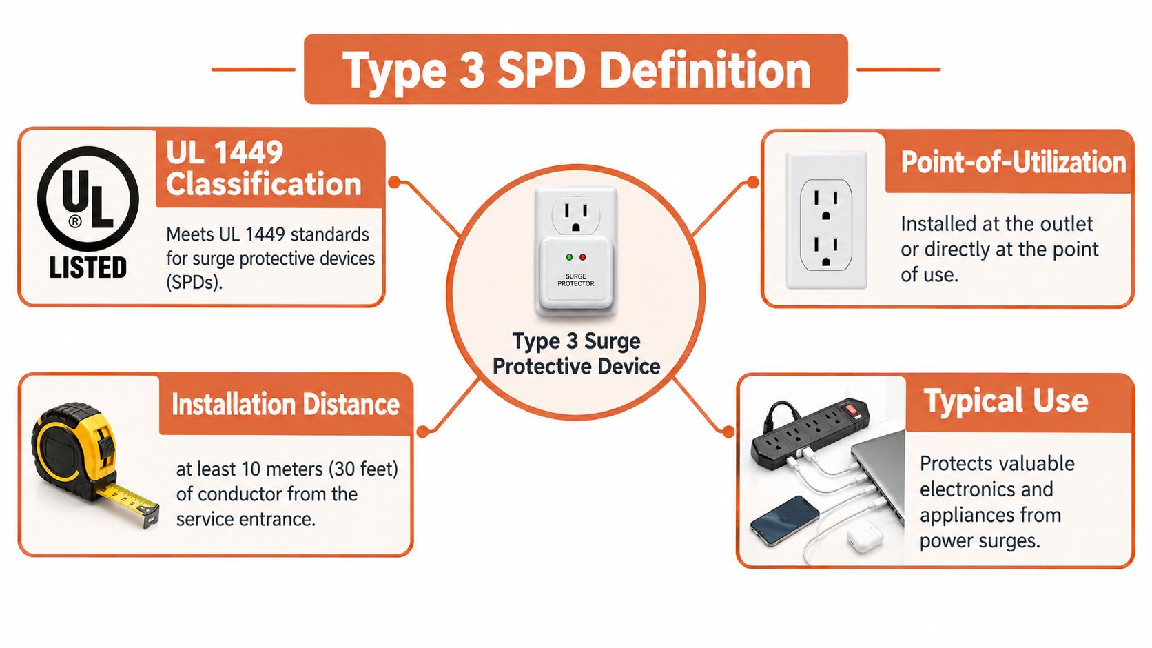
A Type 3 device is defined by where it sits in the electrical system. Under UL 1449 terminology, it's a point-of-utilization device installed at least 10 meters (30 feet) of conductor from the electrical service panel to the utilization point, measured along the conductor routing and excluding conductors supplied with or used to connect the SPD itself, as explained in NEMA's surge protection guidance on Type 3 installation distance.
Read that definition carefully during review. The measurement follows the actual conductor path, not a straight line across a floor plan. It also doesn't include the SPD's own connecting leads. A device a short walk from the panel could still meet the routing distance, while another device farther away on the drawing might not if the circuit path is direct.
Common Formats You Will See on Submittals
- Cord-connected units: Familiar strips or assemblies connected between a receptacle and the load.
- Direct plug-in devices: Compact modules inserted at the receptacle serving the equipment.
- Receptacle SPDs: Devices built into the outlet itself for a cleaner installation at the point of use.
- Protection integrated into utilization equipment: SPD components incorporated by the equipment manufacturer rather than added separately in the field.
None of those formats makes a product Type 3 by appearance alone. The listing, installation instructions, and location in the system decide whether the application is correct.
A Quick Position Check Against Type 1 and Type 2
Type 1 belongs at the service-entrance side of the scheme. Type 2 belongs at distribution equipment downstream of the service. Type 3 belongs at utilization equipment, after branch-circuit protection and with the required conductor distance behind it.
If a submittal calls the only SPD on a project Type 3, stop and ask what's upstream. If a receptacle device is mounted immediately beside the service panel, stop and ask whether the listed installation context has been met. The answer changes the specification. It may also change which product category the engineer should specify instead.
Key Performance Ratings to Verify Before Approval
A Type 3 datasheet can look complete while still hiding a mismatch with your system. Start with the relationship between maximum continuous operating voltage, called MCOV or Uc, voltage protection level (Up), and the protected load's withstand capability. That relationship tells you whether the device can live on the circuit during normal operation and still clamp a transient low enough to matter.
The scope matters too. IEC 61643-11 for low-voltage surge protective devices defines these devices as containing at least one nonlinear component to limit surge voltage and divert surge current, covering AC systems up to 1,000 V RMS at preferred 50/60 Hz frequencies. Within that framework, selection still depends on matching the ratings to the actual system, not on component technology alone.
Why MCOV Deserves the First Check
If MCOV is below the system's sustained line-to-ground voltage, the SPD can conduct during normal operation. That leads to overheating, premature degradation, or failure. Go too far the other way and the higher voltage rating generally increases residual let-through voltage, reducing protection for the load you bought it to protect.
Don't approve based on nominal system voltage alone. Confirm the grounding configuration and the voltage the device will see in its connected mode. Then compare Up or tested clamping data at the specified impulse against what the downstream electronics can tolerate. A low advertised number doesn't help if it's stated under conditions that don't match your application.
Type 3 SPD Ratings to Check on Every Submittal
| Rating | What It Controls | Reviewer Red Flag |
|---|---|---|
| MCOV / Uc | Continuous voltage the device can withstand | Rating selected from nominal voltage without checking grounding |
| Up / let-through voltage | Residual voltage reaching the load during a surge | Value given without the test condition or impulse basis |
| Short-circuit rating | Ability to remain safe under available fault current | No confirmation against the panel's fault current |
| Backup overcurrent protection | Required breaker or fuse coordination | Manufacturer requires a device that isn't in the BOM |
| Thermal disconnection | Safe end-of-life behavior | No clear disconnection method stated |
| End-of-life indication | Ability to detect lost protection | No visible status or remote indication for maintenance |
For a deeper check on how these values are presented and compared, review the basics of a surge protection rating and what each value means before you sign off. Metal-oxide varistors, gas-discharge components, or coordinated combinations can all appear in suitable products. The technology label is secondary. The tested ratings, listing, and system match determine whether the submittal should pass.
How Type 1, Type 2, and Type 3 Devices Coordinate
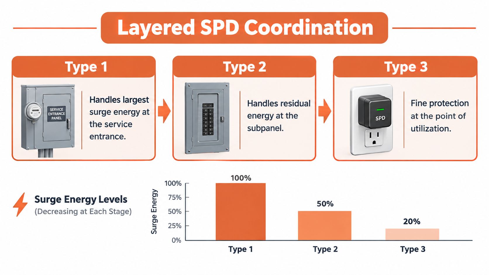
Treat layered surge protection as one system with three jobs. Type 1 equipment handles higher-energy events at the service entrance. Type 2 equipment reduces what remains at distribution panels. Type 3 equipment provides the final local clamping near sensitive loads.
The diagram below shows that division of labor as energy moves toward the equipment.
The Distance Is Part of the Coordination
Conductor distance between stages adds impedance. That impedance helps keep upstream and downstream devices from behaving as if they were connected at exactly the same electrical point. It's one reason a Type 3 unit placed very close to an upstream SPD deserves an engineering check instead of automatic approval.
Location relative to overcurrent protection matters just as much. A Type 3 SPD is installed downstream of service equipment and branch-circuit overcurrent protection, on the load side of the service-disconnect overcurrent device and branch-circuit protection, with at least 10 meters of conductor distance from the service disconnect, as described in UL 1449 material on permitted SPD installation locations. It's connected to an already protected circuit. It doesn't replace the breaker, the service protection, or the upstream SPD.
The short video below is useful when you're walking a junior installer through stage placement before rough-in decisions lock in the routing.
Two coordination errors show up repeatedly. The first is specifying Type 3 protection with no upstream Type 1 or Type 2 device, leaving the small point-of-use unit exposed to energy it wasn't intended to manage alone. The second is placing stages so close together that the assumed separation disappears. Both errors can make a correctly manufactured product perform like a poor specification.
Document the upstream arrangement on the submittal. Mark the panel-to-load routing, note the branch protective device, and confirm grounding and bonding conditions. If those facts aren't on paper, coordination is being assumed rather than verified.
Installation Details That Decide Real-World Performance
The datasheet gives you a tested protection level. The field installation determines how much additional voltage the load sees before that clamping helps. Lead length and routing are where good specifications lose performance.
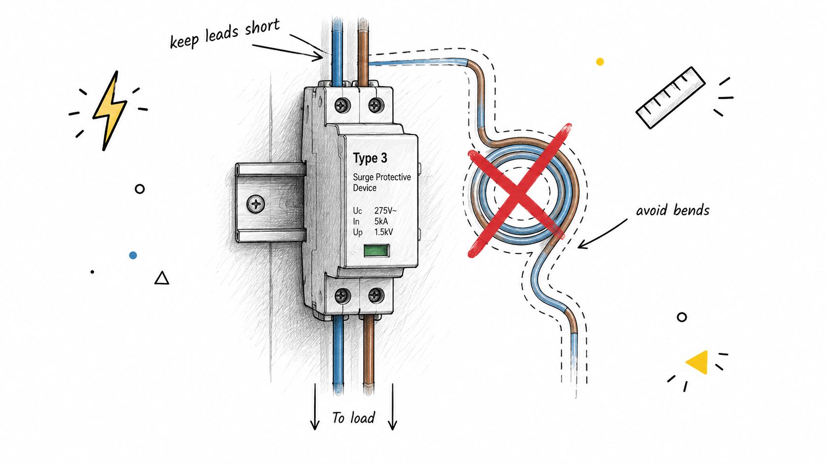
UL 1449 installation instructions require conductors connecting the SPD to the line or bus and ground to be no longer than necessary and to avoid unnecessary bends, with guidance recommending leads as short and straight as reasonably possible, generally one meter or less, because surge voltage increases with the inductive effect of conductor length and bends during a fast transient, according to Intertek's summary of UL 1449 SPD installation requirements.
The rail-mounted example below is a useful reference for keeping the connection path compact inside a control enclosure.
Details to Inspect Before the Panel Closes
- Lead routing: Remove coiled excess wire and avoidable bends. The complete connection path counts, not just the lead supplied with the device.
- Ground path: Keep the route direct and low impedance. A long, indirect ground conductor undermines the protection level the spec relied on.
- Device placement: Mount the SPD close to the protected circuit conductors where the listing and wiring diagram allow it.
- Overcurrent compatibility: Confirm the branch breaker or fuse matches the manufacturer's instructions, including interrupting requirements where specified.
- Conductor size and terminations: Follow the listed wiring instructions and verify field terminations are properly torqued.
A neatly coiled extra lead inside a panel may look tidy. During a fast transient, that coil is part of the voltage problem.
I've seen panels where the specified device was correct, the breaker was correct, and the installation still needed rework because the SPD was mounted where space remained rather than where the leads could stay short. Layout is an electrical decision here. Panel builders should reserve the SPD location during design, not after every other component has claimed the rail.
For receptacle and plug-in formats, the same principle becomes simpler but not automatic. Confirm the device serves the intended load, the branch circuit is the right one, and the installation context still matches the Type 3 listing. Don't let convenience decide placement.
A Spec and Procurement Checklist for Type 3 Devices
Engineering approval and purchasing approval aren't the same task. Engineering confirms the device fits the system. Procurement confirms the exact listed product, documents, and accessories will arrive without a silent substitution. A shared checklist keeps those decisions aligned.
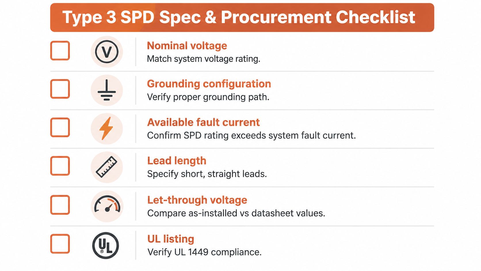
Use the table below as a release gate. If a row can't be marked complete, the BOM isn't ready.
| Review Area | Confirm Before Release |
|---|---|
| System voltage | Nominal voltage, connected mode, and sustained line-to-ground voltage match MCOV |
| Grounding configuration | System arrangement and bonding path verified against the wiring diagram |
| Available fault current | SPD short-circuit rating and backup protection are suitable for the location |
| Upstream SPD scheme | Type 1 or Type 2 device identified by location, listing, and rating |
| Panel-to-load distance | Actual conductor routing documented, excluding the SPD's own leads |
| Device ratings | MCOV, Up at the stated impulse, surge rating, and short-circuit rating recorded |
| End-of-life behavior | Thermal disconnection and status indication confirmed |
| Installation requirements | Lead routing, conductor size, breaker or fuse, and mounting location reviewed |
| Documentation | Listing information, installation instructions, wiring diagram, and compliance records attached |
| BOM cross-reference | Submitted model matches the purchase description with no unapproved alternate |
Where Procurement Usually Gets Tripped Up
The risky moment is the alternate. A supplier offers a unit with the same nominal voltage and a similar form factor, but the Up, MCOV, or short-circuit rating differs. Another alternate needs a backup fuse that isn't included. A third looks identical but has no usable end-of-life indication for the maintenance team.
Send alternates back through the same table. Don't compare them by headline ratings in an email thread. For panel builders, also confirm rail space, receptacle configuration, conductor entry, and whether the replacement changes lead routing. Those details affect both compliance and as-installed performance.
Common Misconceptions That Lead to Misapplied Type 3 SPDs
The most persistent misconception is simple: if it plugs in and says surge protection, it must be Type 3. That isn't how the classification works. UL guidance on Type 3 SPD classification and utilization-point installation describes cord-connected, direct-plug-in, and receptacle units installed with at least 10 m (30 ft) of conductor between the service panel and the SPD, excluding conductors used to connect the SPD itself. The format is only part of the story. Position and coordination complete it.
Ratings Cannot Fix a Bad Application
A higher joule rating doesn't correct a missing upstream device. A lower Up value doesn't correct a location that defeats coordination. A premium device installed in the wrong place can deliver a worse result than a basic listed device installed inside a complete, coordinated scheme.
Marketing comparisons encourage the opposite thinking. Buyers rank products by one number, then assume the installation details will sort themselves out. They don't. The protected load experiences the device, the leads, the grounding path, and the upstream scheme as one system during a transient.
Field test: If removing the upstream SPD from the drawing wouldn't change your Type 3 selection, your review is incomplete.
Another common shortcut is measuring the distance rule as a straight line through walls or across a room. Use the conductor routing. Then exclude the SPD connection conductors from that measurement. Those two details can change the conclusion on compact industrial projects where panels and loads sit close together.
The substitution trap is quieter. Two products may share an enclosure style while differing in MCOV, Up, backup protection, or short-circuit rating. If purchasing swaps one for the other without engineering review, the project no longer has the protection scheme that was approved. Most misapplied Type 3 devices aren't defective products. They're reasonable products released into the wrong system context.
Reviewing Type 3 SPDs on Real Projects
Use a fixed sequence every time a surge protection device Type 3 appears on a drawing or BOM. Consistency catches the details that ad hoc reviews miss, especially when the device looks too small to justify much attention.
A Four-Step Review Sequence
- Confirm the layered scheme: Identify the upstream Type 1 or Type 2 protection and the sensitive load the final stage is meant to protect.
- Confirm installation context: Verify branch-circuit position and conductor distance along the actual routing.
- Confirm device ratings: Match MCOV, Up, short-circuit rating, backup protection, thermal disconnection, and indication to the system.
- Confirm field execution: Check mounting location, lead routing, grounding path, conductor size, and manufacturer instructions before energization.
That sequence also gives procurement a clean way to handle alternates. An approved alternative isn't just a part with matching voltage. It's a listed device that preserves every electrical and installation assumption in the original submittal. If one assumption changes, the reviewer should see it before the order is placed.
A distributor can do more than quote a line item. ATEK Distribution can support BOM review, manufacturer coordination, compliance documentation, and sourcing for hard-to-find protective devices when a specified model is unavailable or an alternate needs proper documentation. Guidance is most useful before release, while engineering, purchasing, and the panel builder can still agree on one coordinated device.
Don't wait for commissioning to discover that the SPD beside the panel, the missing upstream stage, or the substituted receptacle unit changed the design intent. Put the routing, ratings, and upstream device on the submittal record. Then the Type 3 device can do the narrow job it was built for: clamp residual voltage close to the equipment that needs it.
If your next project includes a Type 3 SPD with an unusual voltage, a hard-to-source listing, or an alternate that needs a documented ratings review, contact ATEK Distribution for BOM support, approved alternatives, compliance documentation, and project-specific sourcing assistance. Send your panel details and current BOM so the review can confirm the device, its upstream coordination, and its availability before procurement locks in the wrong part.