
A contractor is reviewing a tray submittal for an industrial feeder run. The plan calls for a wide tray, but the cable schedule is still changing, the support spacing hasn't been confirmed, and nobody has shown that the selected tray meets the project's load requirement. The width looks plausible. The selection isn't complete.
Cable tray sizes are a coupled engineering and procurement decision. Inside width, usable depth, cable arrangement, support span, thermal performance, fittings, and structural rating all affect whether the proposed system works. A tray that passes a fill check can still fail the load check, and a tray with adequate structural capacity can still leave cables crowded or running too hot.
Table of Contents
- Why Cable Tray Sizing Is a Coupled Decision
- Cable Tray Constructions and How They Change Sizing
- Standard Cable Tray Widths and Inside-Width Progression
- Usable Loading Depth and Cable Outside Diameter
- NEC Fill Rules by Tray Type and Cable Class
- NEMA Load Classes, Spans, and What the Designation Means
- IEC 61537 Load, Deflection, and the International Translation
- Thermal Ampacity and the Hidden Limit on Tray Width
- Worked Sizing Scenario From Cable List to Selected Tray
- Quick Reference Table for Common Project Profiles
- Fittings, Supports, and Splice Coordination
- Procurement Checklist and Submittal Fields That Get a Clean Quote
Why Cable Tray Sizing Is a Coupled Decision
The tray submittal is often the first place where the design's separate assumptions meet. Engineering has the cable list, the electrical contractor has the route and support layout, and procurement needs a product description complete enough to source and quote. Each group affects the result.
Consider a project specifying a 24-inch tray on a 20-foot support span. Those dimensions alone don't establish suitability. The design still needs to confirm usable width and depth, cable fill and arrangement, cable weight, the tray's tested capacity at that span, fitting locations, and any required concentrated load. NEMA's load designation can help describe the tray's performance, but it isn't a substitute for the manufacturer's data for the selected construction and configuration (NEMA VE 1 scope and contents).
A reliable review separates the checks, then brings them back together:
- Define the route and cable population. Track what travels through each segment, including branches and planned additions.
- Check physical arrangement. Use cable outside diameters and the applicable fill or single-layer rule.
- Check heat and separation. Confirm the arrangement meets the project's ampacity, spacing, and segregation requirements.
- Check structural performance. Compare cable and tray weight, span, and other specified loads with manufacturer-tested data.
- Coordinate the complete system. Include fittings, supports, splices, covers, and hardware in the specification.
Practical rule: If the quote identifies only nominal width, the distributor may be pricing a product that doesn't match the engineered requirement.
The width is a visible selection. The design basis behind it is what makes it a usable one.
Cable Tray Constructions and How They Change Sizing
Tray construction affects ventilation, cable support, and how the electrical fill calculation applies. Decide which construction the project needs before comparing dimensions.
Ladder tray supports cables on rungs and leaves open space between them. That arrangement is commonly considered for power distribution routes where access, cable exits, and airflow matter. The opening pattern and rung layout still need to suit the cable types and installation.
Ventilated trough has a more continuous base with openings for ventilation and drainage. It can provide closer cable support than a ladder configuration, so confirm that the cable sizes and installation method suit the selected tray.
Solid-bottom tray provides a continuous base. It may be selected where the design calls for that construction, but it has different fill and thermal considerations from open tray. A covered solid-bottom system shouldn't be treated as interchangeable with an open ladder run just because both have the same nominal width.
Materials and finishes also belong in the decision. Industrial projects may specify metal tray with a suitable finish or a nonmetallic system, depending on the environment and project requirements. The required material, finish, fittings, and documentation should follow the specification and manufacturer's product data, not assumptions based on tray appearance.
The selected construction determines which fill limits and thermal checks are relevant. That's why the same cable list may lead to different tray arrangements when the project changes from ladder to ventilated or solid-bottom tray. Check the actual cable types, route conditions, and applicable requirements before choosing a family.
Standard Cable Tray Widths and Inside-Width Progression
For sizing, the dimension that matters is the usable inside width, not just the outside or nominal product dimension. A technical overview referencing the NEMA and CSA framework lists standard inside widths of 6, 9, 12, 18, 24, 30, and 36 inches, equivalent to approximately 152, 229, 305, 457, 610, 762, and 914 millimeters (ABB Electrification Canada cable tray technical overview).
| Inside Width (in) | Inside Width (mm) | Typical Use |
|---|---|---|
| 6 | 152 | Narrow routes, subject to cable arrangement and capacity checks |
| 9 | 229 | Compact routes where the cable schedule fits |
| 12 | 305 | Smaller distribution and control routes, if verified |
| 18 | 457 | Intermediate-width routes |
| 24 | 610 | Wider routes requiring a project-specific fill and load check |
| 30 | 762 | Large cable populations, subject to structural verification |
| 36 | 914 | Wide routes where the layout and load data support the selection |
The progression increases in 3-inch increments through 12 inches, then in 6-inch increments up to 36 inches. The same overview limits outside width to no more than 2 inches (50.8 millimeters) greater than inside width, allowing for side rails and construction. That allowance is useful for interpreting drawings, but it doesn't make outside width a substitute for usable cable space.
Choose inside width against the cable outside diameters, any required separation, future circuits specified by the project, and the physical layout at fittings. A tray that appears adequate on a plan can still fail when large cables must fit side by side or bend through the selected fitting geometry.
Usable Loading Depth and Cable Outside Diameter
Width controls the side-by-side arrangement. Usable loading depth determines how much cable can be accommodated vertically and whether the intended layer arrangement is practical. Typical U.S. specifications commonly use loading depths from 3 to 6 inches, but the usable dimension and permitted cable arrangement need to be verified against the selected product and project requirements (Los Alamos National Laboratory cable tray specification).
For 4/0 AWG and larger multiconductor cables, NEC Article 392 sizing practice requires a single layer, with the tray's inside width at least equal to the sum of the cable outside diameters. At that threshold, cable diameter and width arrangement govern the fit check. A cross-sectional-area calculation alone won't show whether the cables can lie in the required layer.
Depth still matters on a heavy feeder route. A deeper tray may accommodate the required cable height or give the installation more practical room, but it doesn't override a width constraint, thermal limit, or load rating. Nor does extra depth automatically create useful future capacity if the added cables would require a different arrangement.
Check fitting geometry at the same time. Cable minimum bending radii can govern the fitting radius and may make a tight turn impractical even when the straight tray has ample width and depth. The final selection should reflect the usable tray envelope and the cable manufacturer's requirements, not just the dimensions shown in a plan view.
NEC Fill Rules by Tray Type and Cable Class
A fill percentage isn't a universal answer. Under the U.S. NEC Article 392 framework, the applicable check depends on cable class and tray construction. Confirm the governing code edition, project specification, and product documentation for the installation.
| Cable Class | Ladder or Ventilated | Solid-Bottom |
|---|---|---|
| Control and instrumentation cables | Commonly 50% fill limit | Commonly 40% fill limit |
| Smaller multiconductor power cables | Applicable allowable-fill area for the tray type and width | Applicable allowable-fill area for the tray type and width |
| 4/0 AWG and larger multiconductor cables | Single layer, with inside width at least the sum of cable outside diameters | Single layer, with inside width at least the sum of cable outside diameters |
For smaller multiconductor cables, compare their aggregate cable cross-sectional area with the applicable allowable-fill area for the tray type and width. For large multiconductor cables, use the single-layer width check instead. Don't apply the control and instrumentation limits as though they were blanket limits for every power-cable arrangement.
Mixed routes need each relevant rule checked, not just one total area. For example, the control-cable group must meet its applicable fill limit, the smaller power cables must meet their allowable-fill-area requirement, and any large multiconductor cables must fit the required single layer. If the project specifies spare capacity, include the planned future cables in the relevant checks rather than treating spare space as an informal percentage.
For the cable schedule, use actual product data for cable outside diameters. A cable family or conductor size alone may not establish the installed outside dimension. A distributor can help review the wire and cable portion of a bill of materials, including tray cable and wire sourcing, while the engineer confirms the applicable electrical and structural requirements.
NEMA Load Classes, Spans, and What the Designation Means
A NEMA VE 1 designation packs two decisions into one shorthand: support span and working-load category. The commonly used working-load categories are 50 lb/ft for Class A, 75 lb/ft for Class B, and 100 lb/ft for Class C. A designation such as 20C identifies a 20-foot support span paired with the Class C working-load category (NEMA VE 1 scope and contents).
That shorthand helps engineers and distributors communicate, but it is not a universal allowable load for every tray. Capacity depends on construction, material, rung and side-rail design, splice location, support configuration, environment, and the manufacturer's tested load tables. Project specifications often add requirements on top of the distributed cable weight. One published government specification requires a 200-pound concentrated load at mid-span, alongside the specified uniformly distributed load, with a safety factor of 1.5 for the stated test arrangement (published government cable tray specification).
The class letter says nothing about width or depth on its own. Treat the designation as one variable in the coupled sizing decision: width, depth, span, and class move together, and a label covering only span and load category cannot settle the other two. On the quoting side, the class designation is what gets priced first, but the manufacturer's load table is what gets verified.
How to use the designation in a comparison
A 12-inch 20A and a 24-inch 20C are not interchangeable just because both carry a 20-foot span designation. The first indicates a lower working-load class, and the wider tray brings different geometry and potentially different tested capacity. Neither label, by itself, confirms whether the product passes the project's cable-weight and load requirements.
Request the load table matching the specified width, depth, material, and construction at the project's support span. Include cable weight, tray weight, covers, and other supported equipment where applicable. A tray that passes the fill check can still be structurally unsuitable if the combined load exceeds its verified capacity.
IEC 61537 Load, Deflection, and the International Translation
Cross-border projects need more than a conversion between metric and imperial dimensions. IEC 61537 sets requirements and tests for cable-tray and cable-ladder systems, including mechanical performance under specified loading conditions. Its framework covers safe working load, fittings, cantilevers, pendants, load distribution, and deformation.
The cited mechanical limits include lateral bending of support lengths and fittings up to 1/100 of the support spacing, and transverse bending up to 1/20 of nominal width under the nominal safe working load. The standard also includes a collapse check at 1.7 times the rated load. These limits describe tested performance conditions, not a standalone tray selection method. The current international edition identified by the IEC webstore is IEC 61537:2023 (IEC 61537 load-value overview and standard context).
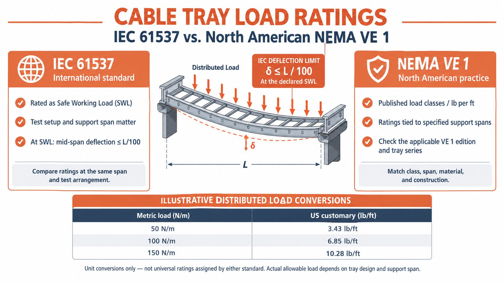
A tray specified at 600 mm width with supports 3 m apart must be checked against the manufacturer's tested load table for that geometry, material, depth, and fitting configuration. Converting a NEMA class label into metric units won't establish equivalence if the test conditions and reporting basis differ.
For a submittal comparison, line up the actual test basis: span, rated load, deflection criteria, configuration, and the product data supporting the declared capacity. Width and depth are part of the specification, but the load and deflection results are what show whether the selected system suits the route.
Thermal Ampacity and the Hidden Limit on Tray Width
Passing the physical-fill calculation doesn't guarantee that the cables can carry their intended current in the proposed arrangement. Thermal ampacity depends on cable type, tray construction, spacing, layering, and cover conditions. A covered tray can change the thermal assessment, and stacking cables or reducing spacing can alter it even when the fill calculation passes.
That's why the familiar 40% to 50% planning rule isn't a universal sizing result. It can be a useful prompt to review space, but it doesn't replace the applicable fill calculation or ampacity determination. A route may meet its fill limit and still require conductor derating; a thermally acceptable arrangement may still violate the applicable physical-fill rule. Keep those checks separate.
A wider tray isn't automatically the remedy for a thermal problem. The cable arrangement and ventilation may matter more than the nominal width.
Depending on the engineering review, the practical fix could be more spacing, a different tray construction, a revised route, or separate parallel runs. Adding width along the same route may not improve heat dissipation enough, particularly if covers or close cable grouping remain unchanged.
For heavy feeders, use manufacturer-certified cable data and evaluate the complete installation before selecting tray dimensions. A sourcing review for a specified conductor, such as 500 kcmil aluminum cable, can help confirm the product data needed for the calculation. The engineer remains responsible for verifying the applicable code and installation conditions.
Worked Sizing Scenario From Cable List to Selected Tray
A useful sizing review starts with the cable list, not a preferred tray width. Consider a representative 480 V industrial feeder sharing a route with control and instrumentation cables. The project team has identified a large multiconductor feeder group that includes 4/0 AWG and larger cables, plus smaller power and control cables. The cable schedule is still subject to confirmation, so the tray selection remains provisional.
Build the route-specific cable schedule
For each cable type, obtain the installed outside diameter and weight from the manufacturer. Record quantity, service, route segment, required segregation, and any documented future circuits. Split the route at branches and fittings, because the cable population and loading can change downstream.
The first attempt is a width-only selection based on the overall cable list. It fails as a complete design: it doesn't show whether the large multiconductor cables fit in a single layer, whether the smaller cable groups meet their separate fill limits, or whether the combined cable and tray weight is acceptable at the specified span.
Apply the checks in order
First, compare the sum of the outside diameters of the 4/0 AWG-and-larger multiconductor cables with the usable inside width. That single-layer check can determine the minimum width before the control-cable fill calculation is considered. Next, calculate the applicable fill for the smaller power and control groups under the tray construction and project requirements.
Then test the cable arrangement thermally, including any cover or spacing conditions. Add only project-defined future cables to the schedule, and assess their effect on both fill and weight. Don't use an undocumented spare allowance as a substitute for identified future demand.
Finally, compare cable load plus the tray and other supported loads with the manufacturer's tested data for the selected width, depth, material, support span, and fittings. If the candidate fails any check, revise the width, depth, support arrangement, or route, then repeat the affected checks. The result is a documented selection, not a guess based on cable count.
Quick Reference Table for Common Project Profiles
A profile table can narrow the product search, but it can't replace the cable schedule or manufacturer load data. The entries below identify standard width options and the information still needed to establish a final selection. The specified span and NEMA class must come from the project's structural requirement and verified product data, not the facility label.
| Project Profile | Width x Depth | Span (ft) | NEMA Class |
|---|---|---|---|
| Small commercial feeder | Select from standard inside widths after cable and fill review | Project-defined | Verify from load table |
| Heavy industrial distribution run | Select from cable arrangement and load calculation | Project-defined | Verify from load table |
| Data center bus route | Select after construction, segregation, and thermal review | Project-defined | Verify from load table |
| Utility switchyard control run | Select from cable schedule and applicable control-cable fill | Project-defined | Verify from load table |
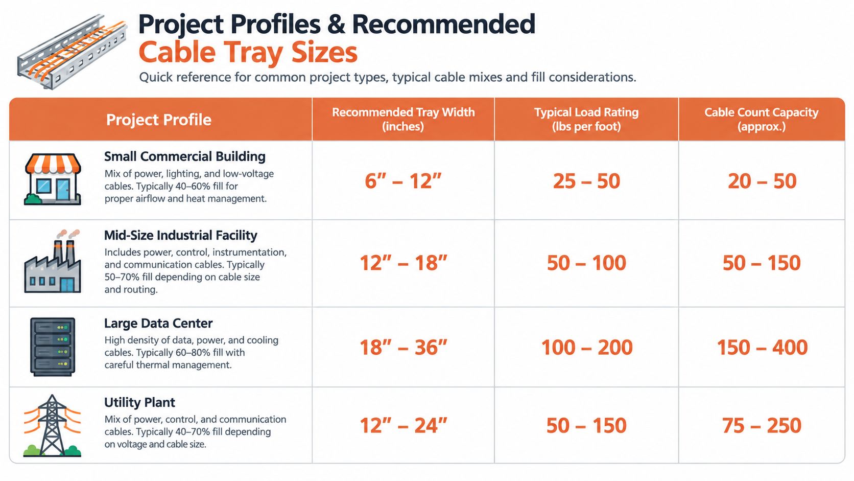
Use the table as a shortlist, then verify fill, cable arrangement, ampacity, weight, and span for the actual route. This overview may help orient a project team before it reviews its own submittal:
Fittings, Supports, and Splice Coordination
The straight tray selection doesn't settle the route. Horizontal and vertical fittings must accommodate the cable's minimum bending radius, and branch fittings must suit the cable paths leaving the main run. Check the fitting radius against the cable manufacturer's requirement rather than assuming the tray width defines an acceptable turn.
NEMA VE 2 recognizes support placement one-quarter span from a splice, mid-span from a splice, or directly beneath the splice. The one-quarter-span arrangement is identified as preferred because it minimizes splice stress and deflection. Tray lengths should be at least as long as the selected support span, and the schedule should show support spacing and splice locations (Eaton cable tray design considerations).
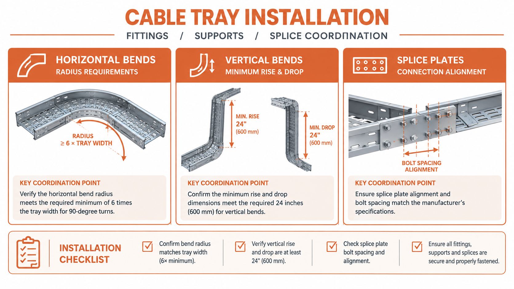
Coordinate the tray length, support type, splice hardware, fittings, and cover specification in the same package. Supports have to carry the complete cable-tray wiring system, not just the installed cable quantity (NEMA VE 2 installation guidance).
For an adjacent cable-support application that uses a different system, such as a Caddy J-hook, verify the specified product and installation requirements rather than treating it as a replacement for a designed tray run. Mixing support types without coordinating the route can complicate installation and documentation.
Procurement Checklist and Submittal Fields That Get a Clean Quote
A complete request for quotation should identify the engineered selection, not just the nominal width. Include:
- Dimensions: Usable inside width and usable depth.
- Construction: Tray type, material, and finish.
- Structure: Support span, NEMA or IEC load class, and verified load data.
- System components: Fittings, splice hardware, covers, and compatible supports.
- Project documentation: Required product submittals and applicable Buy American Act, Trade Agreements Act, or supplier-diversity documentation where required.
If you're coordinating contractor pricing with the electrical scope, Black Rhino Electric's electrical quote request is a separate resource for that conversation. For tray procurement, provide the route drawing, cable schedule, specifications, and approved alternatives so the quoted product can be checked against the design basis.
ATEK Distribution can assist with BOM review, hard-to-source tray families, manufacturer coordination, approved alternatives, and compliance documentation. Send the complete tray package rather than a width-only request to help keep quoting and project review aligned.
Contact ATEK Distribution for cable tray sourcing, project-specific BOM review, or help evaluating approved alternatives when availability or lead times change. Visit ATEK Distribution to discuss the requirements and documentation for your project.