You've opened a dark fixture expecting a lamp change, but the replacement tube won't start. The ballast label is faded, the spare on the truck looks close, and maintenance needs the area back in service. Choosing a ballast for T5 lamps at that point requires more than matching the wattage printed on the glass.
The useful question isn't whether the replacement fits inside the housing. It's whether the replacement matches the complete electrical system, and whether repairing that fluorescent system still makes sense.
Why T5 Ballast Selection Goes Deeper Than Lamp Wattage
Consider a replacement that bolts into the existing mounting holes and lists the expected lamp wattage. After installation, the lamps start poorly or the fixture no longer responds correctly to its controls. That's a hypothetical service call, but it illustrates the selection error: mechanical fit and nominal wattage don't establish compatibility.
The missing detail might be the supply-voltage rating, starting method, supported lamp count, or control interface. A different ballast factor can also change the fixture's output even when the lamps appear to operate normally.
Treat the fixture as an assembly
The ballast, lamps, sockets, controls, and fixture wiring have to work together. Substituting a component without identifying the rest of that assembly turns a straightforward repair into troubleshooting by trial and error.
Before requesting a replacement, separate what you know from what you're assuming:
Confirmed information: Legible lamp markings, ballast model, fixture label, supply identification, and control model.
Unverified information: A replacement someone previously installed, a handwritten stockroom description, or an assumption based on the neighboring fixture.
Missing information: An unreadable wiring diagram, undocumented emergency equipment, or sockets whose configuration hasn't been inspected.
Practical rule: An installed component is evidence of what's present, not proof of what belongs there.
This distinction matters especially in buildings maintained through several repair cycles. Don't automatically reproduce the last technician's substitution. Compare the installed equipment with the fixture documentation and the proposed manufacturer's application data.
Define an acceptable replacement before ordering
For a maintenance repair, the objective is usually to restore the intended operation without changing the lighting design or controls. For a planned upgrade, a different output or control arrangement may be acceptable, but it needs engineering approval rather than an undocumented field substitution.
A useful purchasing description therefore identifies the operating requirements, not just a discontinued catalog number. That gives the supplier a basis for evaluating an alternative and gives the installer a clear acceptance standard.
The right replacement is a documented system match, not just the nearest available ballast.
Electronic Versus Magnetic T5 Ballasts
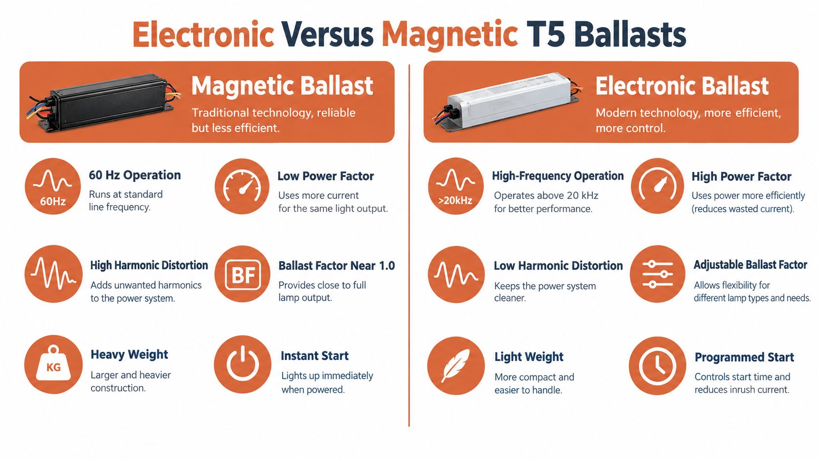
For conventional linear T5 fluorescent systems, electronic operation is the starting point for selection. Treat magnetic equipment encountered in an unusual fixture as a reason to investigate its documentation, not as an interchangeable T5 ballast category.
The comparison below is a useful orientation, but individual product data must govern selection.
What the efficiency comparison actually means
T5 lamps were designed for high-frequency electronic ballasts rather than conventional magnetic arrangements. A Hong Kong government technical review of T5 lighting reports improved fluorescent efficacy above 10 kHz, ballast losses falling from 24 W to approximately 6 W in its cited twin-lamp circuit, and potential overall lighting-energy reductions of approximately 20% to 30% with a suitable luminaire.
Those are system-specific comparisons, not a savings guarantee for every replacement. In particular, reducing ballast losses isn't the same as reducing total fixture consumption by the same proportion.
Electronic vs Magnetic T5 Ballasts at a Glance
Criterion
Electronic T5 Ballast
Magnetic T5 Ballast
Application suitability
Intended operating approach for conventional linear T5 systems
Don't assume suitability without explicit fixture and lamp documentation
Operating frequency
High-frequency operation specified by the product
Conventional magnetic operation isn't a substitute for the specified electronic system
Power factor
Verify the published value at the intended operating condition
Check the complete circuit and any compensation
Harmonic distortion
Require documented performance
Don't assign a value based only on ballast construction
Ballast factor
Match the lighting calculation
Don't assume an equivalent output
Starting method
Confirm the exact starting designation
Don't infer starting behavior from appearance
Weight and mounting
Verify dimensions, mounting, and thermal instructions
Neither weight nor mounting-hole alignment establishes compatibility
The infographic's simplified categories shouldn't be treated as universal specifications. Magnetic doesn't automatically mean instant start, and electronic doesn't automatically mean dimmable or adjustable.
Power quality needs a datasheet
A Philips fluorescent-ballast technical specification illustrates the detail involved: programmed start, automatic restart, 120–277 V operation, frequency above 42 kHz, power factor above 0.98, total harmonic distortion below 10%, and lamp-current crest factor no higher than 1.7.
These aren't interchangeable terms. Power factor concerns the relationship between real and apparent power; harmonic distortion describes current-waveform distortion. Ballast factor concerns relative lamp output. A favorable value for one doesn't establish acceptable performance for the others.
For submittals, ask for those characteristics explicitly. A description that says only “electronic T5 ballast” leaves too much unresolved.
Identifying the Correct Ballast for a T5 Fixture
Start with the lamp marking, then reconcile it with the ballast and fixture labels. Don't begin with the replacement catalog and work backward toward something that looks plausible.
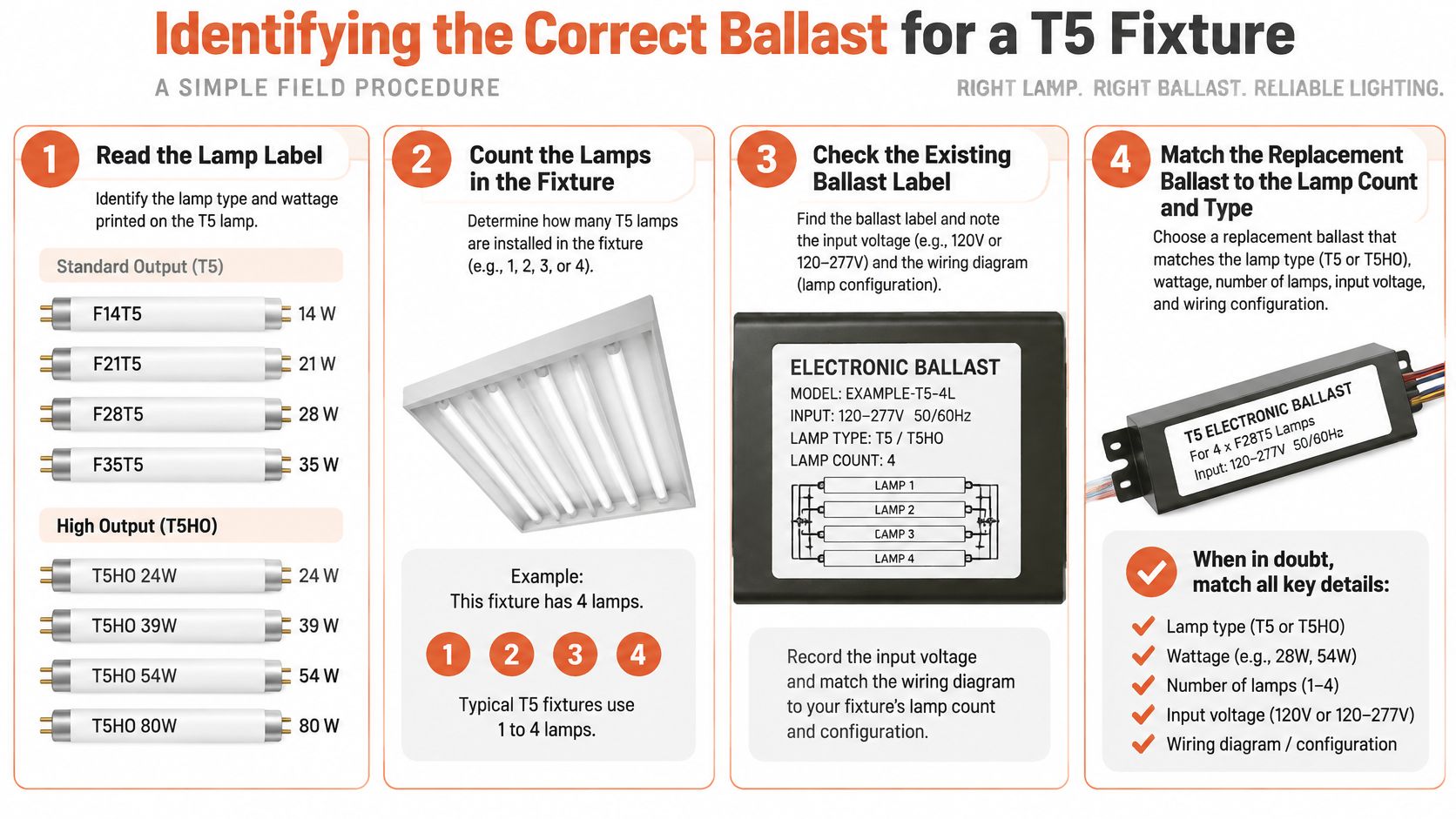
This field guide summarizes the identification sequence.
Read the complete lamp designation
Capture the entire marking, including the output-family designation. Relevant families include F14T5, F21T5, F28T5, F35T5, and T5HO lamps at 24, 39, 54, and 80 W, as reflected in T5 electronic-ballast application listings.
Don't shorten a high-output designation to “T5” on the purchase request. The supplier needs the actual lamp application, not just the tube family.
T5 tubes are 16 mm, or approximately 5/8 inch, in diameter and are approximately 50 mm shorter than commonly used T8 lamps, according to the Manual on Efficient Lighting. That dimensional difference matters when checking socket placement and fixture fit, but dimensions still don't establish electrical compatibility.
Match the operating configuration
Count the lamps connected to each ballast, rather than assuming the fixture's total lamp count equals its ballast configuration. Photograph any separate emergency equipment and identify which lamps it serves.
Next, verify supply voltage against the replacement's actual rating. The commercial voltage range discussed earlier doesn't mean every ballast accepts every supply within that range. A fixed-voltage product and a broadly rated product require different purchasing descriptions.
Starting method deserves its own check. Programmed start, rapid start, and instant start aren't procurement synonyms. Confirm the manufacturer's designation, then verify that the socket and wiring arrangements support it.
Ballast factor must also be deliberate. Published T5 ballast application and performance data identify 1.00 as common for T5HO applications and 0.95 or 1.15 for some T5HE applications; those latter values correspond to approximately 95% and 115% of reference lamp output.
A higher factor isn't automatically an upgrade. It can change input demand and thermal loading, so select the factor required by the lighting design.
Inspect the sockets before sending the request
Identify miniature-bipin arrangements, rotary-locking sockets where specified, and four-pin locking arrangements on applicable twin-tube lamps. Don't assume all small fluorescent sockets provide the same electrical connections.
Send the supplier a compact identification package:
Lamp information: Full designation and clear photographs of the markings.
Fixture information: Label, internal layout, mounting space, and socket photographs.
Control information: Dimmer or control model, interface, and emergency-lighting arrangement.
Wiring information: A legible diagram and photographs taken before disconnection.
If a label is unreadable, say so. A documented information gap is safer than a guessed specification.
Wiring and Installation Practices for T5 Ballasts
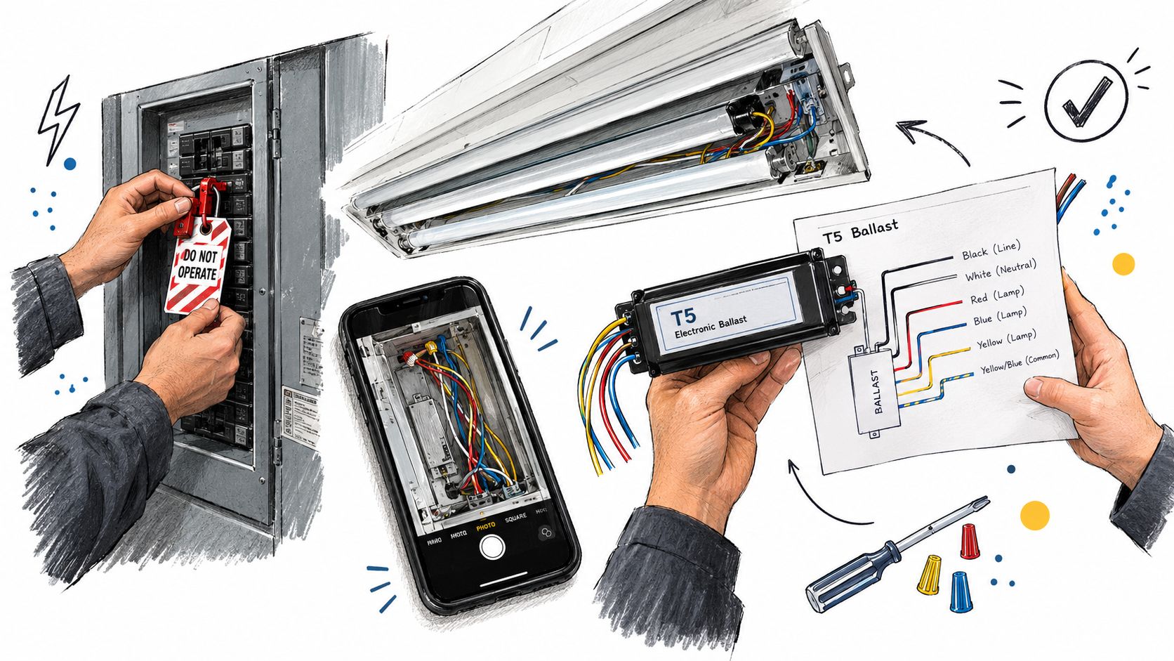
A replacement should begin with circuit isolation, not wire cutting. Qualified personnel should de-energize and lock out the circuit, verify the absence of voltage under the site's electrical-safety procedure, and identify any additional supply associated with emergency equipment.
Safe access comes before component replacement.
Follow the replacement diagram
Photograph the existing connections before disturbing them, but use those photographs as a record rather than an installation authority. Compare the replacement ballast's diagram with the actual fixture arrangement, including sockets, controls, and grounding.
Lutron's fluorescent dimming-system installation guidance identifies several important checks: fully seated lamps, correct socket selection, proper dimmed-hot and switched-hot connections, maximum lamp-wire length, and grounding.
Socket connections: Confirm that the required contacts remain separate and intact.
Control conductors: Identify conductors by function and the applicable diagram, not by an assumption about color.
Lamp leads: Keep routing and length within the replacement manufacturer's limits.
Grounding: Verify continuity through the intended grounding path before energizing.
Connector selection also needs application-specific review. The discussion of whether WAGO connectors are code approved is a useful starting point, but a connector still has to suit the conductor, enclosure, ratings, and installation instructions.
Preserve the intended heat path
Mount the ballast using the specified fixture-body arrangement. Where the manufacturer requires flush mounting, raised supports or attachment to a lamp-cover plate can defeat the intended thermal contact.
The heat-management principle is straightforward: restoring light doesn't prove that the ballast is operating under acceptable thermal conditions. Check the mounting interface and enclosure condition rather than judging the repair only from lamp operation.
Commissioning check: Accept the repair only after the fixture starts, operates, and responds to its controls as intended.
Use the video as supplementary installation context, not a substitute for the replacement's wiring diagram or the site's safety procedures.
After reassembly, check starting behavior, visible flicker, control response, dimming range where applicable, and abnormal heating. Confirm that lamps are fully locked into their sockets and that no lead has been pinched during closure.
Record the installed model and any approved changes in the maintenance file. That record prevents the next service call from beginning with the same identification problem.
Repair, Replace, or Retrofit to LED
A failed ballast creates a purchasing decision, but it should also trigger a lifecycle review. Repair is reasonable when it preserves a serviceable, supported system. It's less attractive when the facility is repeatedly investing labor in deteriorated equipment.
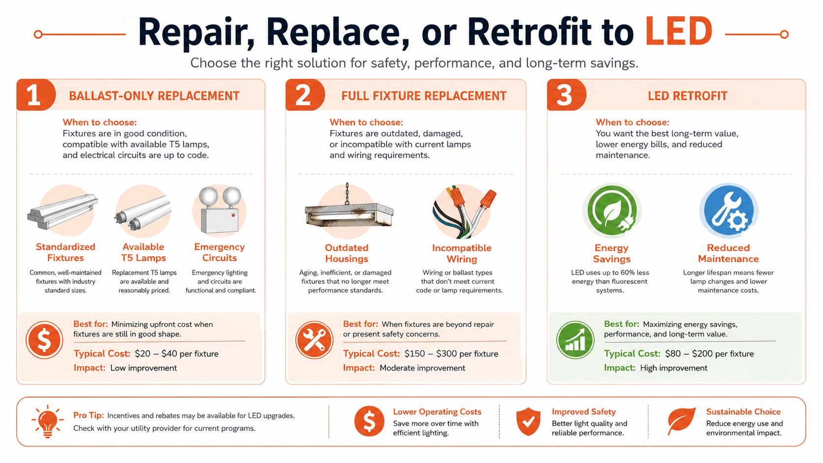
The available paths have different prerequisites.
When retaining fluorescent makes sense
A ballast-only repair can be a practical choice where housings and optics remain sound, replacement lamps are available, and the existing emergency-lighting and control arrangements should remain unchanged. It can also suit a building awaiting a broader renovation.
That's a continuity decision, not necessarily the lowest lifecycle-cost decision. Include future lamp procurement, maintenance access, and mercury-containing-lamp handling in the evaluation.
Availability must be checked by market and lamp category. For example, the European lighting-industry lamp-exit timetable identifies February 25, 2023 as the market-placement cutoff for circular T5 fluorescent lamps under RoHS. That specific restriction shouldn't be generalized into a claim that every T5 lamp is prohibited everywhere.
Separate the LED options
For a ballast-compatible LED proposal, require the exact existing ballast model to be accepted by the LED manufacturer. For ballast bypass, require the specified rewiring arrangement and socket requirements. Neither option should proceed on physical fit alone.
Review the proposed retrofit's applicable UL listing, installation instructions, dimming behavior, and emergency-lighting compatibility. If the housing, wiring, or optical system needs substantial rehabilitation, include complete fixture replacement in the comparison.
A project-level LED lighting retrofit evaluation should compare installed scope and continuing maintenance, not just tube prices.
Decision input
Ballast-only repair
LED tube retrofit
Full fixture replacement
Existing housing and optics
Retain if serviceable
Inspect suitability for reuse
Replace the assembly
Controls and emergency operation
Confirm restoration of existing functions
Require documented compatibility
Specify the required functions
Procurement
Confirm ballast and lamp support
Confirm tube, wiring, and compatibility documentation
Confirm complete luminaire submittal
Cost worksheet
Parts, access, labor, future relamping
Parts, conversion labor, controls work
Equipment, installation, controls work
Energy comparison
Actual system input
Proposed system input
Proposed luminaire input
Populate the worksheet with your own fixture count, lamp cost, labor cost, operating schedule, and energy rate. Compare alternatives at acceptable illumination and control performance. Lower input power isn't a useful saving if the replacement no longer supports the work performed below it.
Troubleshooting Common T5 Ballast Failures
Symptoms narrow the investigation; they don't identify the failed component by themselves. A dark lamp can point to a lamp, socket, wiring, control, or supply problem before the ballast is condemned.
Use the identification record to establish what should be installed, then compare that with the fixture's condition.
No start or intermittent starting
Check the lamp application and starting arrangement against the approved configuration. With the circuit safely isolated, inspect lamp seating, socket contacts, damaged leads, and connections.
For applicable multi-lamp systems, Lutron's T5 socket and wiring guide requires sockets on yellow or blue-with-white-stripe leads to be connected in parallel rather than series. An incorrect connection can resemble a ballast failure, so verify topology before ordering another component.
Compare the installed assembly with its application diagram
Intermittent operation
Loose seating or connections
Inspect under isolation, then test after correction
Flicker or cycling
Connections and control compatibility
Compare behavior with the approved operating configuration
Unexpected light output
Lamp designation and specified ballast factor
Compare the installed label with the lighting schedule
Flicker, dimming instability, and noise
If the problem occurs only during dimming, investigate the control interface and operating configuration rather than immediately replacing the ballast. Don't attempt to solve a control mismatch by changing lamp wattage.
Buzzing or ticking warrants inspection, but the sound alone doesn't establish harmonic interaction or a failed internal component. Where several fixtures behave abnormally together, evaluate the shared supply and controls; the discussion of power quality issues provides useful context for that broader investigation.
Heat, odor, and immediate isolation
Fluorescent ballasts can remain energized and reach approximately 150 °F even when the fixture is switched off; buzzing, ticking, vibration, melting-plastic or ozone odors, charring, and deformation are warning indicators requiring isolation and investigation, as described in fluorescent-lighting loss-prevention guidance.
A wall switch in the off position is not a safe-isolation procedure.
Smoke, a melted housing, or charring takes the fixture out of routine troubleshooting. Disconnect the affected equipment, preserve required illumination through an approved temporary arrangement, and investigate the damage before returning it to service.
Don't open the ballast or infer internal capacitor temperature from the switch position or exterior appearance. Follow the manufacturer's handling instructions and site isolation procedure. Review application loading, thermal contact, and obstructed ventilation without energizing visibly damaged equipment merely to reproduce the fault.
Sourcing, Compliance, and Next Steps for T5 Projects
Procurement should receive a verified application package, not just a photograph accompanied by “send an equivalent.” Include fixture quantities, full lamp designations, existing ballast labels, supply information, controls, emergency arrangements, and the required repair or retrofit scope.
Define documentation before approving alternatives
A federal fluorescent-luminaire specification requires nationally recognized testing-laboratory listing, UL 935 compliance, and ANSI C82.1 compliance for its covered T4/T5 compact-fluorescent ballasts. Apply those requirements within their stated scope rather than treating that document as a universal specification for every linear T5 installation.
For federal procurement, identify any Buy American Act or Trade Agreements Act requirements in the contract and request product-specific documentation.
Technical approval: Require the alternate's application data, wiring diagram, and relevant compliance documents.
Supply planning: Confirm availability and identify who approves substitutions if lead times change.
Lifecycle alignment: Specify whether the purchase supports continued fluorescent maintenance or a planned conversion.
A distributor can review the BOM, coordinate manufacturer questions, and identify hard-to-source or alternate components. Engineering approval still belongs with the responsible project authority. Selecting a ballast for T5 equipment works best when sourcing and technical acceptance use the same documented requirements.
ATEK Distribution offers BOM review, hard-to-source component sourcing, manufacturer coordination, and compliance-documentation support for T5 repairs and lighting upgrades. Visit ATEK Distribution with your lamp markings, ballast-label photographs, wiring diagram, and project specification to request availability, alternate-part identification, or project-specific procurement assistance.
The register is installed, the face looks right, and the schedule says the outlet matches. But the room still has a dead corner, the airflow sounds harsh, or the measured supply doesn't line up with the design. On plan day, that mismatch often starts before anyone cuts the duct: a spiral duct register was chosen by appearance or nominal size instead of by how it works with the connected system.
A round terminal can't be judged in isolation. Duct diameter, pressure class, material, airflow, discharge pattern, and the register-to-duct connection all affect the result. The practical approach is to review the submittal against the duct schedule, install the assembly carefully, then verify performance through testing, adjusting, and balancing (TAB).
Why Spiral Duct Register Selection Starts With the Duct
An installer bolts on a register that matches the drawing. The grille is centered, the screws are tight, and the finish looks clean. Once the air handler is running, though, occupants complain that the room feels stuffy, or a technician finds the outlet isn't delivering its scheduled airflow.
That outcome doesn't automatically mean the register is defective. The connected duct may have a different diameter or pressure class than the submittal assumes. A sharp transition, a poorly aligned opening, leakage at the connection, or an unsuitable vane direction can also change how air reaches the space. A register is one component in an air-distribution system, not a standalone part.
Start with the duct schedule and design conditions. Confirm the connected diameter, material, pressure class, airflow direction, and design CFM. Then check that the register's construction and performance data apply to those conditions. A face-size match is only a starting point, not proof that the assembly will deliver the required airflow or throw.
Plan-day check: If the register submittal doesn't identify the duct connection and operating conditions it's intended for, ask for clarification before approving it or cutting the opening.
That systems-first review matters whether the job uses direct-mount registers or a separate tap. For a broader look at sourcing HVAC products for project requirements, see ATEK's HVAC product information. The selection principle remains the same: match the terminal to the duct and design conditions, then verify the installed result.
What Spiral Duct Registers Are and How They Fit the System
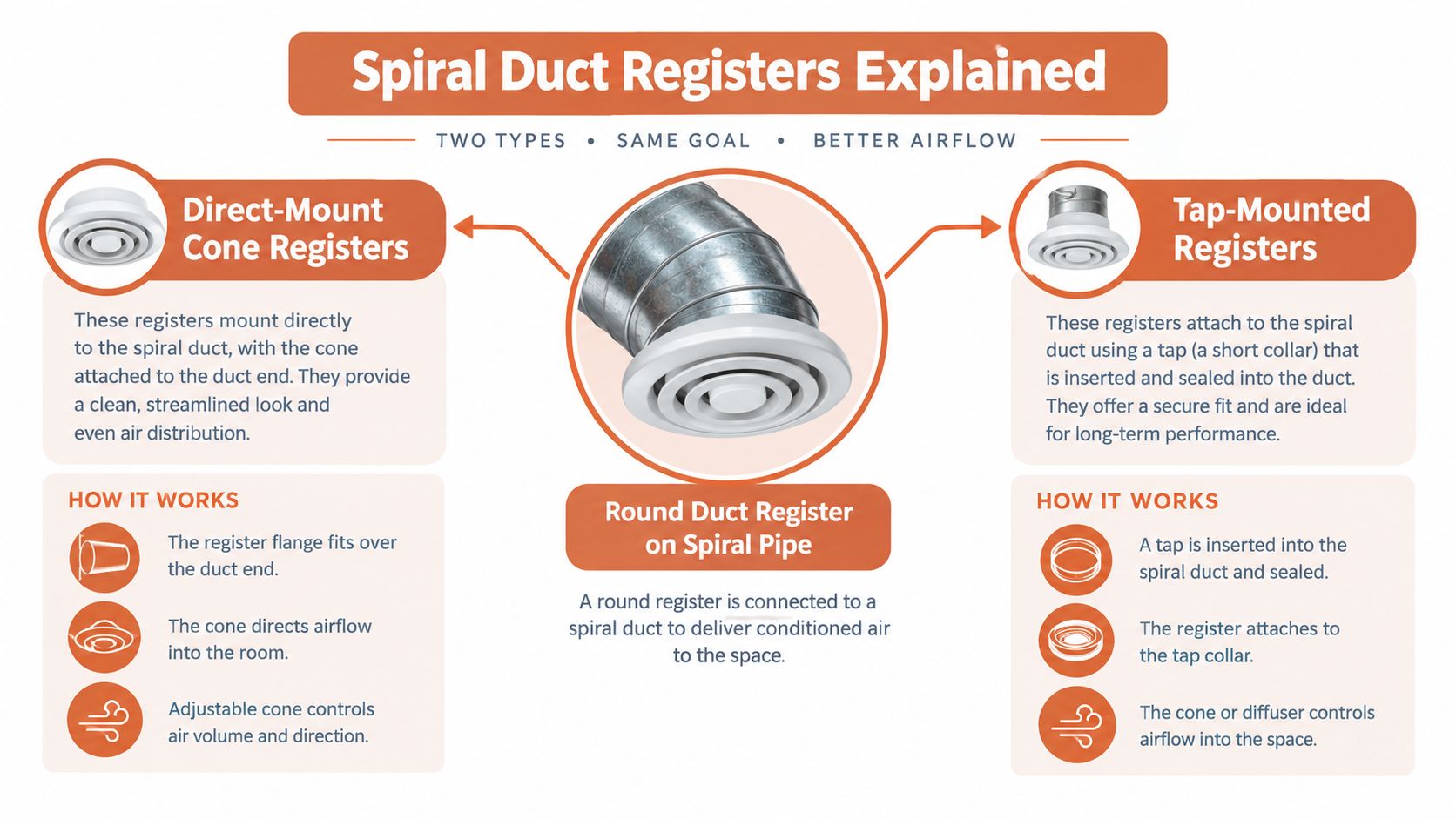
A spiral duct register is a supply or return terminal built to mount on round ductwork, usually spiral lockseam pipe. One family attaches directly at a prepared cutout in the duct wall; the other connects through a tap or saddle fitting. That mounting difference decides the opening size, the hardware, and how the airstream enters the terminal, so it belongs on the submittal rather than in an installer's assumption.
Two constructions cover most jobs:
Direct-mount cone or flange registers seat against the round duct at a cutout, eliminating a rectangular tap and its transition hardware when the opening and register geometry line up.
Adjustable-blade grille registers shape or redirect the discharge. Blade direction is field-adjustable, which helps during balancing, but the chosen setting still has to hold up against measured airflow and pressure.
A spiral register and a rectangular diffuser may serve the same room, yet their connection geometries differ and their published throw and pressure-drop values are measured on different mounting arrangements. The same caution applies to generic round grilles: a catalog part only counts as a spiral duct register when it is engineered for the specified duct connection and operating conditions.
Why the round-duct standard matters
Spiral duct fabrication sits inside a long-standing sheet-metal standards framework. SMACNA's duct construction standards have governed this work for decades, and the industrial duct standard carries a dedicated spiral-duct chapter covering Classes 1 and 2 air systems. That framework matters on plan day because dimensional tolerances, leakage limits, fitting construction, and pressure class all define the conditions a register's performance data assumes. When a submittal lists throw and pressure drop, those figures trace back to a duct built to that standard.
For procurement, write descriptions that separate direct-mount from tap-mounted configurations and state the duct diameter and design conditions alongside the face size. A clear spec keeps engineers, installers, and buyers from treating a nominal dimension as a performance description. ATEK's heating, ventilation, and air-conditioning product category shows how suppliers organize these mounting configurations for project ordering.
Sizes, Materials, and Pressure Classes You Can Order
On plan day, a register that matches the spiral diameter can still land outside the operating envelope. Pressure class, material, temperature, reinforcement, and attachment method carry as much weight as the nominal connection size. A substitution that holds the face dimension while changing any one of those parameters needs technical review, not an automatic approval.
SMACNA construction guidance covers round long-seam and spiral duct from 4 inches through 60 inches in diameter, including reinforced and unreinforced construction. It addresses positive or negative pressures from 4 to 20 inches water gauge, with pressure classification driving material selection and reinforcement. The same guidance sets temperature limits by material (SMACNA construction guidance).
Spiral duct and register compatibility
Parameter
Range
Notes
Duct diameter
4 to 60 inches
The register's connection must match the scheduled spiral size and construction type.
Pressure
4 to 20 inches water gauge, positive or negative
Establish the design pressure class first; diameter alone says nothing about suitability.
Carbon or stainless steel temperature
Ambient to 650°F
Check the register, gasket, and attachment ratings against the operating temperature.
Galvanized steel temperature
Up to 400°F
Don't assume a standard galvanized assembly is rated above its stated limit.
Aluminum temperature
Up to 120°F
Confirm material and temperature compatibility before specifying.
The ordering takeaway is plain: a register chosen by neck or face size alone can end up fastened to duct running a pressure or temperature the assembly was never rated for. Negative pressure deserves the same scrutiny, because the register, gasket, and fastening method must suit the direction of flow along with the class.
A separate SMACNA industrial duct standard extends that envelope considerably, reaching deeper negative pressures, higher positive pressures, and spiral diameters well beyond the construction guidance above. Those figures describe the industrial standard's design scope, as the standards discussion earlier in this article established. They are not a rating for any register. Treat them as context for what the duct can be built to handle, then verify the register's own class and product documentation before assuming compatibility.
This matters downstream at TAB. The pressure class and material on the approved submittal are what the balancing technician compares against measured static pressure and throw at the scheduled CFM. If the installed register differs in class or construction from what was submitted, the catalog pressure-drop figures stop applying, and the balancing report loses its baseline.
Matching a Register to Your Duct Before You Cut the Opening
Before ordering or cutting, compare the schedule and submittal line by line. A catalog entry that appears to match the face dimension can still omit the pressure class, duct material, or airflow conditions needed to judge compatibility.
Review the connection and design conditions
Start by confirming the duct diameter at the exact register location, not just the main-run size. Check whether the terminal is direct-mounted or tap-mounted, and make sure the submittal describes the connection arrangement shown on the drawings. If the opening dimensions or fitting geometry aren't clear, resolve them before fabrication.
Next, identify the pressure class and operating environment from the project documents. Verify that the register assembly, gasket, and attachment method are suitable for the material, pressure direction, and temperature conditions. Don't infer a pressure rating from the product's face size or appearance.
Then review the performance information. Confirm scheduled CFM, airflow direction, discharge pattern, and the throw criterion used in the design. Ask whether the published data apply to the mounting arrangement and operating conditions on the job. Where information is absent or ambiguous, request clarification rather than treating the closest catalog option as equivalent.
Catch the mismatch before field work
The most common review gap is accepting a catalog match on face size without checking pressure class or material. Flag that gap in the submittal comments and require the supplier or manufacturer to document compatibility with the schedule. That simple review can prevent a cutout that leaves the installer trying to adapt a terminal that doesn't fit the duct or design.
For maintenance teams evaluating existing duct conditions before a repair or modification, this overview of signs your ductwork needs attention offers useful context. On a new installation, keep the focus on project-specific documents: the approved schedule, duct construction details, register data, and any required gasket or attachment information.
Installing the Register Without Leaking or Misaligning
Direct-mount registers can reduce transition hardware by eliminating a rectangular tap, but the advantage depends on a properly prepared opening. A distorted or inaccurately aligned cutout can leave gaps at the duct wall or prevent the register flanges from seating evenly.
Inspect the opening for burrs, distortion, and edges that could interfere with the gasket or register. Remove debris and confirm the opening follows the approved dimensions. A rough edge or an uneven cut can compromise the connection even when the register itself is correctly sized.
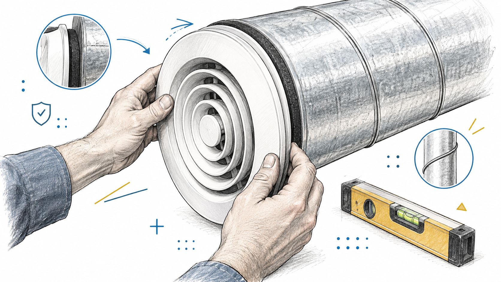
Seat a continuous gasket against the duct wall, then fit the assembly so the upper and lower flanges sit flush. Secure it mechanically as specified for the product and installation. Check that fasteners hold the register evenly without pulling one side away from the duct. Before the ceiling or wall closes, inspect the full interface for visible gaps or movement.
Check the discharge orientation
Set extractors or adjustable vanes to the intended discharge pattern. Their orientation should follow the approved design, not an installer's assumption based on how the register looks from the floor. Record any field adjustment that changes the approved setup, so the TAB technician can test the actual configuration.
A direct-mount installation removes a transition, but it doesn't remove the need to inspect the airflow path. Confirm that nearby structure, insulation, or other services won't obstruct the outlet or make the intended pattern impossible. A short visual check before close-up can catch misalignment while the connection is still accessible.
The following installation video provides a visual reference for the assembly sequence:
Verifying Airflow, Throw, and Pressure Drop After Install
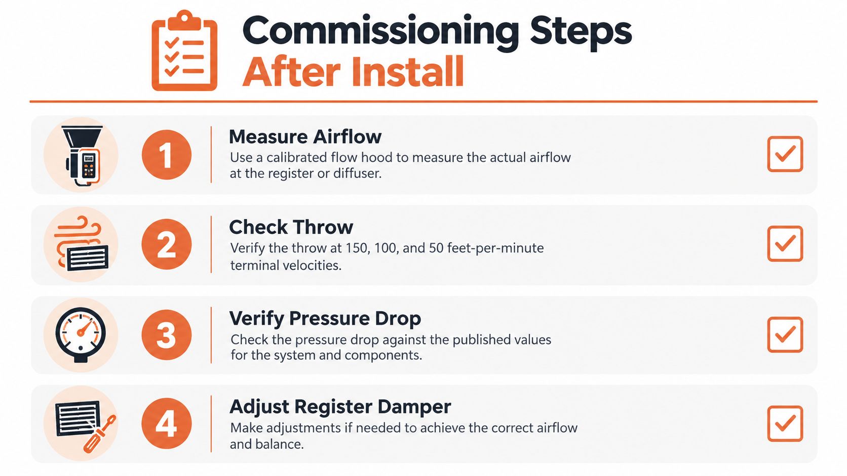
A register isn't commissioned when it's fastened in place. Verify the installed airflow after filters, dampers, grilles, and air-handler components are in position. A calibrated flow hood can measure terminal airflow under installed conditions; compare the reading with scheduled design CFM and record the result.
A practical acceptance benchmark is airflow within ±10% of scheduled design, as described in the RESNET verification reference (RESNET HVAC component verification). Some residential verification protocols permit the greater of ±20% or 25 CFM. Use the criterion required by the project or applicable verification protocol, and don't treat one benchmark as a universal replacement for the contract documents.
Read throw data in context
Published performance data for direct duct-mounted spiral grilles reports throw at terminal velocities of 150, 100, and 50 feet per minute under isothermal conditions (Nailor spiral grille performance data). These values describe progressively weaker air movement as the jet travels into the served space. Match the chosen throw to room geometry, mounting height, airflow volume, and acceptable drafts.
Isothermal data doesn't automatically describe heating or cooling operation. Temperature differences introduce buoyancy effects, so the actual discharge path may differ from catalog conditions. Adjustable-blade angle also changes effective outlet area and pressure-loss behavior. After adjusting vanes or register controls, measure airflow again instead of assuming a catalog curve predicts the installed result.
Pressure and airflow belong in the same TAB record. The ASHRAE Duct Fitting Database includes resistance information for more than 200 spiral, rectangular, and flat-oval fittings, supporting pressure-drop calculations for specified fitting sizes and airflow conditions (ASHRAE acoustics and duct-fitting research). Document measured CFM, static pressure, register setting, and any balancing adjustment. For a plain-language refresher on how system resistance affects design and testing, consult this static pressure guide for HVAC systems.
Acoustic, Cleanability, and IAQ Trade-Offs in Sensitive Spaces
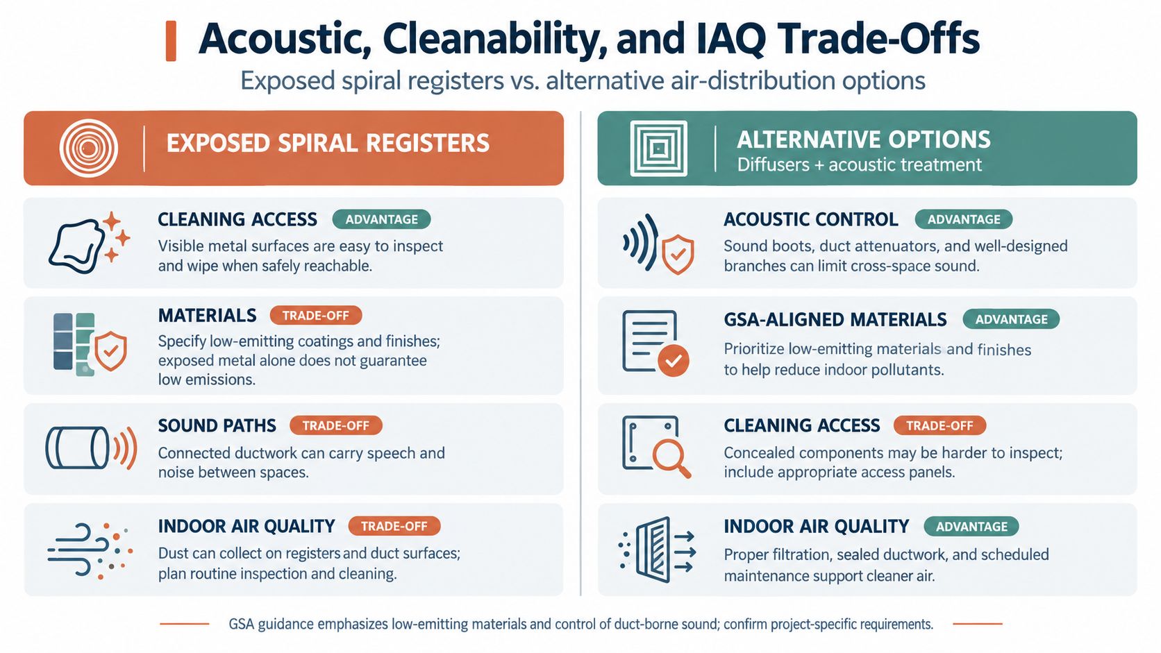
A classroom sits directly under an exposed spiral run, and the register that looked cleanest on the reflected ceiling plan is also the shortest sound path between the fan and thirty students. Exposed spiral duct with a simple metal register can suit a space visually while performing poorly on sound, hygiene, or maintenance. Ductwork transmits sound between rooms, and an outlet becomes a noticeable sound path when fan noise or high-velocity airflow reaches an occupied area.
The U.S. General Services Administration advises specifying quiet HVAC systems and limiting small, high-velocity ductwork where noise could produce unacceptable conditions and costly remediation. The acoustics and duct-fitting research cited earlier also measured transmission loss rising steeply with frequency in galvanized spiral steel duct, with enough spread between constructions that catalog values cannot predict what a given outlet will sound like in a finished room. Frequency, geometry, surface construction, and airflow resistance all matter. Treat published attenuation figures as evidence of that, never as a guarantee of installed performance.
Choose the configuration for the room
For classrooms, healthcare spaces, laboratories, and food-production environments, weigh occupancy, noise, cleaning access, condensation control, and hygiene requirements together before approving the submittal. A terminal box or silencer may be warranted when the design needs more acoustic control or a different connection arrangement. Internal acoustic lining can reduce sound along the run, provided it tolerates the facility's cleaning and contamination-control program. If the lining cannot survive the cleaning method or traps moisture, the acoustic gain turns into a maintenance and IAQ liability. Check whether the submittal specifies lined or unlined duct upstream of the register, because that one line item changes both the sound path and the cleaning procedure.
Spiral systems can be engineered for low leakage, though that answers only part of the selection question. Industry guidance reports properly engineered spiral duct leakage below 1%, while also identifying leakage as a concern for wasted energy and indoor air quality (ACHR News guidance on spiral duct). Leakage performance says nothing about whether an exposed register is quiet enough, cleanable enough, or appropriate for a sensitive space.
Coordinate rated penetrations and maintenance
Where ductwork crosses rated assemblies, coordinate the register location and duct route with required fire and smoke protection. UL states that fire dampers are tested as part of fire-resistance-rated vertical or horizontal assemblies under UL 555, while smoke dampers and combination products are evaluated under UL 555S and related standards (UL fire damper guidance). The required protection depends on the assembly and applicable project codes. A damper where none is required still adds static pressure and a maintenance point, so confirm placement rather than blanketing every register, and obtain listing and installation documentation before approving a substitution.
Keep the maintenance record tied to the installation. Remove registers as appropriate for the facility's cleaning program, inspect gaskets and connections, and file the approved submittal, installation photos, and TAB results together. That record lets the next technician distinguish a changed setting or damaged connection from a design issue, and it closes the loop between what was submitted and what was measured.
For a project with hard-to-source register sizes or submittals that need review against duct and operating conditions, contact ATEK Distribution. ATEK can assist with sourcing, manufacturer coordination, approved alternatives, and procurement documentation to help keep HVAC and electrical project requirements aligned.
The line stops, a drive reports undervoltage, and the PLC needs a restart. There's no damaged cable, no open breaker, and no obvious explanation for why production lost its sequence. Maintenance wants to replace the suspect component. Purchasing wants a part number. Neither team has enough evidence yet.
Power quality issues become expensive when teams buy a remedy before defining the disturbance. Before a retrofit, establish what happened at the equipment terminals, what the load needs to remain operational, and what the replacement equipment must demonstrate during commissioning.
A utility interruption and a production interruption aren't the same thing. The incoming supply may recover quickly while operators still need to clear faults, restore control states, inspect work in progress, and restart machinery. For a plant manager, the meaningful measure is time until the process is stable, not merely time until voltage returns.
The transition to digitally controlled and electronically automated operations made this distinction economically important. A U.S. Department of Energy report reviewing EPRI research estimated historical annual interruption and power-quality costs of approximately $79 billion, including about 4.3 momentary interruptions per customer site associated with roughly $52 billion in losses, and approximately 1.2 sustained outages, totaling about 106 minutes, associated with another $26 billion; commercial customers accounted for more than 70% of estimated interruption costs, industrial customers for nearly 26%, and residential customers for less than 2%.
Those are historical estimates, not a current forecast or a calculation of your plant's exposure. Their practical value is the distinction between a short electrical event and a much longer operational consequence.
Budget around the process consequence
For a retrofit, identify which loads determine whether production continues. A control-power supply, PLC rack, contactor coil, or drive may be more consequential than its purchase price suggests. Protecting the whole facility isn't automatically the most economical approach.
Document the restart burden. Record fault clearing, manual intervention, sequence recovery, and inspection requirements.
Separate damage from interruption. Equipment can stop without suffering a permanent failure.
Define acceptable behavior. Specify whether the process must continue, pause safely, or shut down in a controlled state.
Assign ownership. Operations defines the consequence, engineering defines the electrical requirement, and procurement obtains supporting product documentation.
Procurement rule: Buy against an operating requirement, not against a disturbance label.
A purchase order that says “power protection” leaves too much unresolved. A useful specification identifies the protected load, measured exposure, required response, installation constraints, and acceptance evidence. That gives maintenance a testable remedy and purchasing a defensible basis for comparing alternatives.
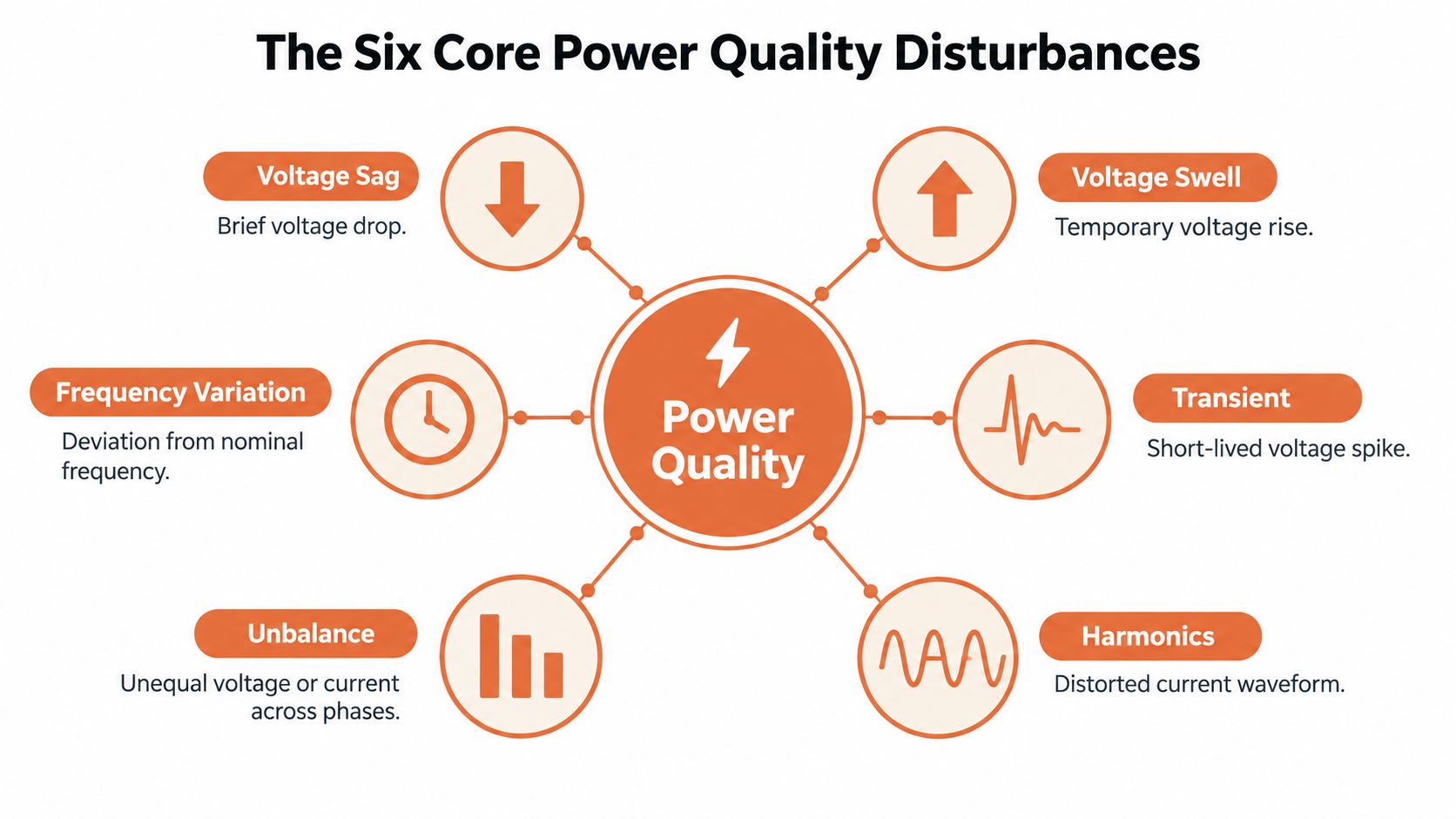
The Six Core Power Quality Disturbances
When a drive trips or a control resets, the alarm describes the equipment's response, not necessarily the cause. Use disturbance terms to frame the investigation, then compare them with monitoring evidence before selecting equipment or writing a purchase specification. IEEE thresholds can support classification, but the measured event and the protected load's response must guide the decision.
Voltage sags are reductions in RMS voltage, while swells are increases. Transients are abrupt deviations from the normal waveform. Harmonics and interharmonics are waveform components at integer and noninteger multiples of the fundamental frequency. Frequency variation affects the fundamental frequency itself, and voltage unbalance describes differences among phase voltages.
The diagram groups the six disturbance categories. Use it to orient the investigation, not to diagnose a facility.
Power Quality Disturbance Quick Reference
These duration and magnitude descriptions are qualitative screening terms, not universal limits. Causes and symptoms are leads for investigation, not proof. Confirm the event with measurements before comparing mitigation products.
Disturbance
Typical Duration
Typical Magnitude
Common Cause
Typical Symptom
Voltage sag
Brief event
Reduced RMS voltage
Motor starting, welding, upstream faults
Contactor dropout or control reset
Voltage swell
Event-dependent
Increased RMS voltage
Investigate switching and operating-state changes
Equipment overvoltage alarm
Transient
Abrupt event
Impulsive or oscillatory deviation
Investigate switching activity and lightning exposure
Electronic reset or failure requiring waveform confirmation
Flicker deserves separate attention rather than being forced into one disturbance category. For complaints limited to dimmed lighting, this resource on how to stop dimmer lights from flickering offers a lighting-specific starting point. It does not replace an industrial power-quality study.
Before sourcing a remedy, establish whether affected equipment shares a panel, feeder, or operating cycle. Then compare alarm records with power-quality measurements. Undervoltage, overvoltage, and thermal alarms call for different evidence, and a loose connection, equipment defect, or control-program problem can mimic a supply disturbance.
Use the disturbance label to make the work order specific. Use commissioning measurements to confirm that the selected equipment addresses the event recorded at the facility.
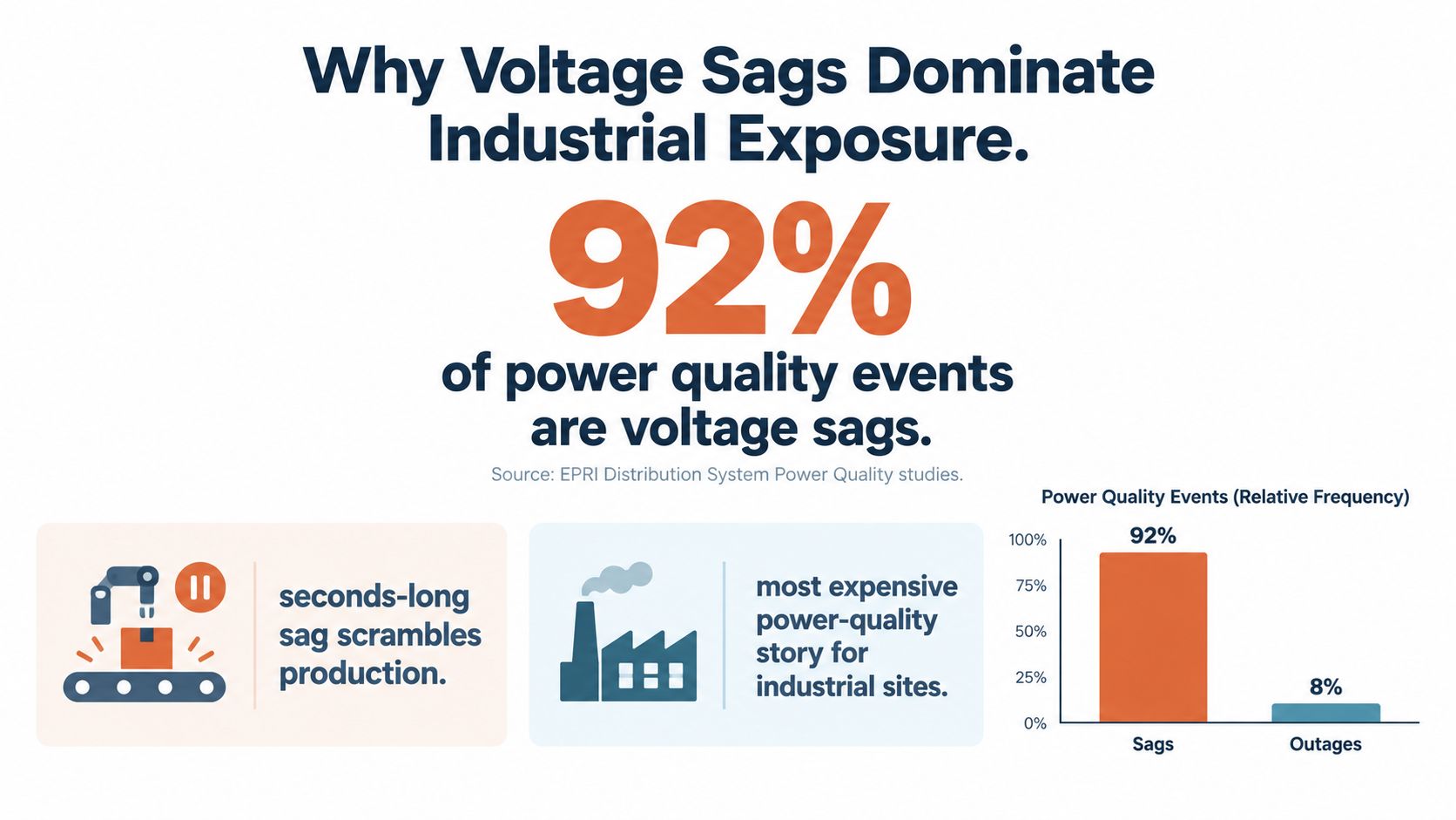
Why Voltage Sags Dominate Industrial Exposure
A feeder fault or motor start can pull voltage down long enough to reset a control system, even when the equipment looks normal by the time maintenance arrives. For procurement, that creates a specific problem: choose protection against measured exposure, not a generic product label.
The EPRI Distribution System Power Quality Monitoring Survey recorded 107,834 three-phase RMS-variation measurements across 146,661 monitoring days, using 277 instruments from June 1, 1993, through June 1, 1995. Average monitored-site rates included approximately 1.18 annual incidents in the 85%–90% voltage band, 0.38 interruptions below 10% of nominal, and a 95% confidence interval of 14–20 annual events below 0.70 per-unit voltage. These historical results show how sag exposure can be quantified, but they do not predict conditions at a specific plant or support a universal share of industrial power-quality events.
Treat the graphic's percentage as illustrative, not as a design basis. The survey results above do not establish that claim, so it should not drive specifications or financial justification.
Specify ride-through around the load
Ride-through capability describes whether equipment stays in an acceptable operating state during a defined disturbance. A useful specification states voltage depth, duration, affected phases, loading, and acceptable recovery behavior. “Sag resistant” gives suppliers too little to prove.
NIST's power-quality troubleshooting guidance identifies motor starting, welding equipment, and upstream faults as common sag causes. Before sourcing equipment, establish whether the event removes control power, trips a drive, drops a contactor, or disrupts recovery. That distinction determines whether control-only support is sufficient or the process load also needs protection.
Require documented performance against the specified sag envelope, then test recovery during commissioning. Continued operation and a safe restart are separate acceptance conditions. Use monitored voltage-duration exposure to compare UPS systems, dynamic voltage restorers, and control-power conditioning. Select against the recorded event and the plant's operating requirement, not the broad phrase “power quality.”
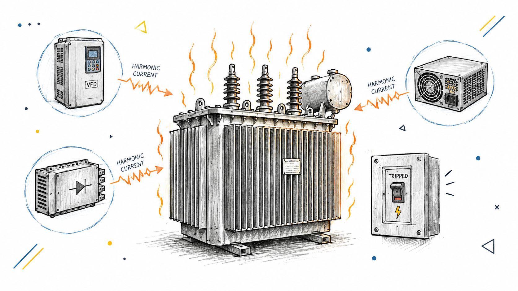
How Harmonics Stress Equipment in Practice
A transformer that runs hot during production may be carrying harmonic losses that a spot current reading will miss. Harmonic distortion needs to be assessed alongside load and temperature, especially where drives, switched-mode supplies, LED drivers, UPS rectifiers, or electronic chargers operate.
Nonlinear loads draw harmonic currents. System impedance converts those currents into voltage distortion, so readings depend on both where the loads connect and how strong the supply network is. The renewable-energy integration guidance supports assessing distortion at the connection point, rather than relying on a converter's nameplate.
Total harmonic distortion, or THD, summarizes distortion but does not identify which conductors are heating or which harmonic orders dominate. A procurement decision based on THD alone can therefore miss the equipment duty that determines transformer sizing, filter selection, and commissioning acceptance.
In a three-phase, four-wire system, triplen harmonics add in the neutral instead of canceling. Harmonic currents can also circulate in a delta-connected transformer secondary, creating heat that primary overcurrent protection may not adequately detect, as the NIST guidance discussed earlier notes.
Before specifying a replacement or filter, require evidence that connects operating conditions to equipment stress:
Measure individual orders. Keep the harmonic spectrum, not just a summary value.
Log temperature with load. Compare similar production conditions when evaluating a change.
Correlate communications complaints. Check whether interference coincides with converter operation before assigning the fault to network equipment.
A cooler replacement transformer does not prove that harmonic emissions meet the project's requirements.
For IEEE 519 coordination, identify the applicable point of common coupling and obtain the governing project limits before issuing a purchase specification. The cited integration guidance gives a 5% total current-distortion threshold and a 2.5% voltage harmonic-distortion criterion for certain interconnection contexts. These figures are not universal IEEE 519 limits.
Choose filters against the measured spectrum and operating range, then verify performance during commissioning. A transformer designed for the thermal duty can address heating, but it does not establish acceptable emissions or confirm downstream controls will keep operating.
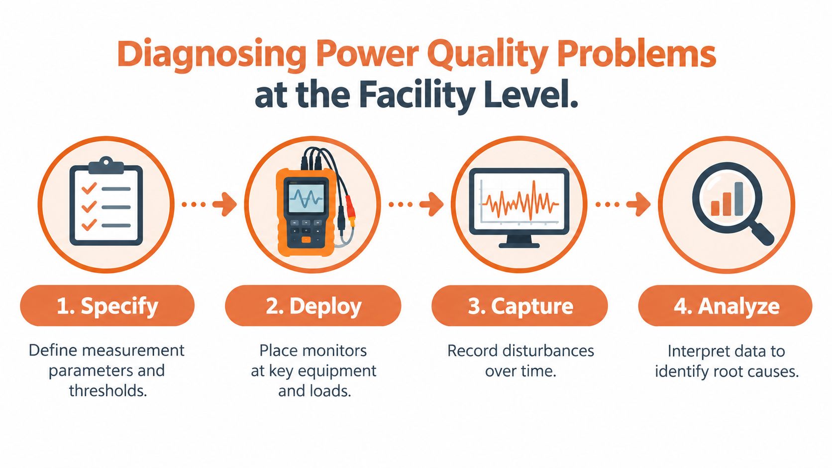
Diagnosing Power Quality Problems at the Facility Level
A defensible study should produce evidence that an engineer can use and a buyer can put into a specification. A report containing only a worst-case THD screenshot or a list of alarms won't support a reliable equipment selection.
IEC 61000-4-30 defines repeatable in-situ measurement methods for 50 Hz and 60 Hz systems, covering frequency, voltage magnitude, flicker, dips, swells, interruptions, transients, unbalance, harmonics, interharmonics, mains signalling, rapid voltage changes, and current measurements, according to the IEC measurement standard description. It is a measurement and interpretation standard, not a standalone set of acceptable facility limits.
The diagnostic sequence should be agreed before instruments are installed.
Specify the evidence chain
Define the study. Name the phenomena, measurement method, trigger settings, monitored operating states, and required deliverables.
Deploy at useful boundaries. Use synchronized monitors at the service entrance and critical distribution points so events can be compared.
Capture more than alarms. Retain RMS voltage, event duration, phase angle, waveform triggers, harmonic spectrum, and relevant current measurements.
Correlate with operations. Compare captures against motor starts, welding cycles, utility fault records, feeder loading, and equipment trip timestamps.
Ask who owns the raw recordings and whether the contractor will provide instrument settings and time-synchronization details. Those records matter when a utility, manufacturer, or third-party engineer needs to examine the same event.
Keep energy records and electrical evidence distinct
Facilities managing several energy streams may also use resources such as Blue Gas Express's mobile gas energy data solutions. Keep those operational records separate from electrical waveform evidence; shared timestamps can support correlation, but energy-use records don't establish the cause of a voltage disturbance.
The final study should distinguish measured condition, equipment susceptibility, and applicable limit. An event may meet a utility agreement yet still interrupt a sensitive process. Conversely, an equipment trip doesn't by itself prove a utility violation.
Require the assessor to explain that distinction before accepting a turnkey mitigation quotation.
When the Disturbance Is Not Inside Your Building
A fault observed inside the plant doesn't prove that the plant generated the disturbance. Shared feeders, neighboring loads, and upstream operating changes belong in the investigation when local evidence doesn't explain the event.
An analysis of U.S. residential sensor readings near data-center activity examined approximately 770,000 readings and reported that three-quarters of the most distorted readings occurred within 50 miles, while more than half of households with the worst distortion were within 20 miles. That geographic association warrants investigation, but proximity alone doesn't establish causation or responsibility for a particular facility's problem.
Build a cross-boundary record
Compare synchronized recordings at the incoming service and affected downstream buses. Where access and agreements permit, request corresponding utility or neighboring-site measurements. Preserve baseline records from before major energization changes and compare equivalent operating conditions afterward.
Establish timing. Determine whether the incoming disturbance precedes the internal response.
Compare current and voltage. Their relationship helps engineers investigate contribution rather than merely detect distortion.
Document operating changes. Include major load additions, switching events, and changes in source configuration.
Agree responsibility criteria. Use the applicable utility agreement, connection requirements, and engineering assessment.
The distinction between broad operational visibility and event-level evidence also matters when considering advanced metering infrastructure capabilities. Specify the measurements needed for the investigation rather than assuming every metering platform captures suitable waveforms.
Capital decision: Locate the disturbance before committing to a permanent mitigation package.
The remedy may be internal, utility-side, or shared. Even when local protection is justified to maintain production, document whether it addresses susceptibility or the originating condition.
That distinction affects cost allocation, acceptance testing, and future expansion. A local device that keeps one machine running doesn't necessarily resolve the condition affecting the surrounding distribution system.
Matching Mitigation Equipment to the Actual Disturbance
Choose mitigation by verified function under the intended operating conditions. Product category names are useful for screening, but they aren't performance guarantees.
A surge protective device addresses transient overvoltage; it doesn't restore missing RMS voltage during a sag. A K-rated transformer accommodates specified harmonic heating duty, but it doesn't remove harmonic currents or provide ride-through. Grounding and bonding must be correct, yet neither should be sold as a universal cure for upstream voltage disturbances.
Mitigation Equipment vs. Disturbance Type
“Conditional” means the manufacturer must document the relevant function and operating range.
Device
Sag
Swell
Transient
Harmonic
Unbalance
UPS
Ride-through within rating
Conditional
Conditional
Verify input emissions
Conditional
Surge protective device
No
Not sustained regulation
Intended function
No
No
Dynamic voltage restorer
Voltage support within rating
Conditional
Not default function
Conditional
Conditional
Power conditioner
Conditional
Conditional
Conditional
Conditional
Conditional
Passive harmonic filter
No
No
No
Tuned application
Not default function
Active harmonic filter
No
No
No
Compensation within rating
Conditional
K-rated transformer
No
No
No
Thermal accommodation
No
Grounding and bonding correction
Not voltage restoration
No
Supports protection installation
Not filtering
Not phase balancing
Compare installation and operating trade-offs
A UPS introduces storage, maintenance, bypass, and input-emissions considerations. A dynamic voltage restorer requires confirmation that its compensation envelope fits the measured disturbance. Passive filters require careful application to the system, while active filters need verified compensation capacity across changing load states.
At the service entrance, consider aggregate exposure and utility-interface requirements.
At distribution panels, assess feeder-specific problems and space for mitigation.
At equipment terminals, protect process-critical controls or loads where targeted support is justified.
Don't stack technologies just to make the specification look complete. Require each device to address an identified condition, and require the combined system to demonstrate acceptable behavior.
Maintenance, Commissioning, and Sourcing Practices That Stick
Commissioning should verify the conditions that justified the purchase, not merely confirm that the equipment energizes. Keep the original monitoring baseline, approved settings, acceptance criteria, and post-installation recordings together. Maintenance needs that package when the next load addition changes the system.
Start with routine thermal inspections and waveform captures under representative operating states. Record transformer loading, neutral current, filter status, and equipment alarms alongside temperatures. Retest ride-through after changes to drives, control supplies, transfer arrangements, or protection settings.
Test combinations, not isolated nameplates
Solar, batteries, EV charging, and flexible data-center loads require coordination among converters, protection, storage controls, and the supplying network. NERC's long-term reliability assessment describes inverter-control and coordination concerns and records 2025 Eastern Interconnection data-center load reductions of 1,800 MW, 1,300 MW, and 540 MW. These are system-level events, not predicted voltage disturbances at an individual plant.
Their procurement implication is practical: require operating scenarios and test evidence, not only nominal ratings.
Model relevant configurations. Have the engineer determine the need for short-circuit analysis, harmonic scans, and electromagnetic transient studies.
Check control modes. Review inverter tuning, transfer behavior, intentional load shedding, and protection coordination.
Validate after energization. Compare waveforms across representative loading, charging, generation, and transfer states.
Retain approved settings. Treat undocumented firmware or parameter changes as a commissioning concern.
Make replacement sourcing evidence-based
For a K-rated or otherwise specially engineered transformer, retain the documented thermal-duty basis rather than relying on the designation alone. For IEEE 519 coordination, retain the agreed point of common coupling, applicable limits, operating cases, and acceptance results.
A replacement drive, UPS, breaker, or filter should pass a compatibility review before purchasing approves an alternate. Compare interfaces, installation constraints, electrical ratings, protection requirements, documented emissions, and the operating behavior that matters to the process. Manufacturer approval and engineering acceptance should remain explicit.
Use electrical equipment pricing and lead-time planning to organize procurement discussions, but confirm actual availability and approved alternatives for the specific project. A distributor can support BOM review, hard-to-source replacements, manufacturer coordination, and compliance documentation; the responsible engineer still owns the design decision.
Managing power quality issues means preserving the evidence from diagnosis through replacement. That continuity prevents an emergency purchase from undoing the performance established during commissioning.
ATEK Distribution supports BOM and specification review, hard-to-source electrical components, manufacturer coordination, and documented alternatives for power protection and distribution projects. Visit ATEK Distribution with your monitoring findings, equipment requirements, and replacement priorities to discuss availability and project-specific procurement support.
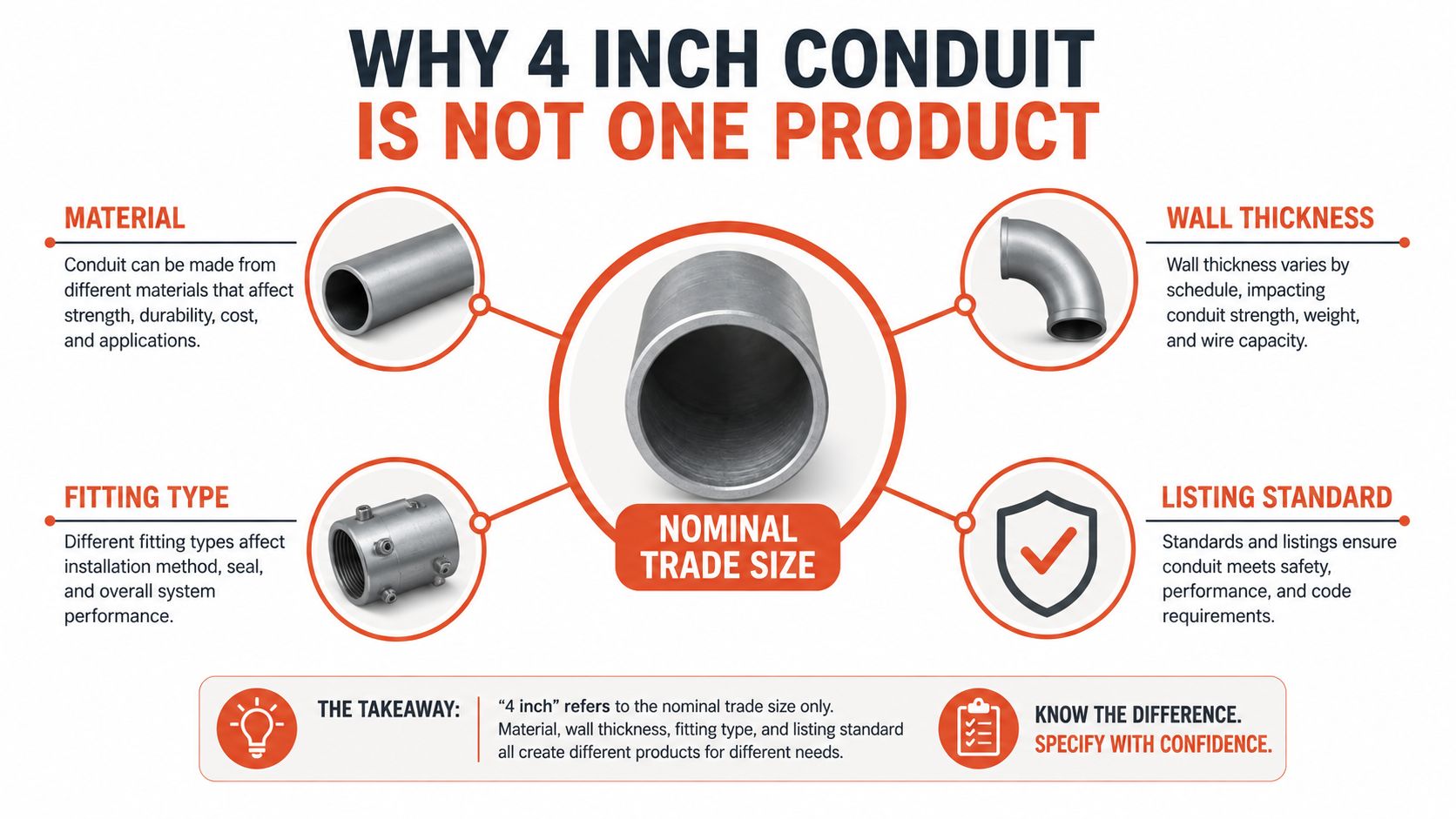
Four-inch conduit is a nominal trade size, not a fixed dimension or a guaranteed conductor capacity. A 4-inch Schedule 40 PVC raceway has about 12.554 square inches of internal area, while 4-inch EMT has about 14.753 square inches, so the same trade-size label can mean different usable space.
That's why the popular shortcut, “Pick 4-inch conduit and check the wire count,” can steer a project wrong. The right selection depends on the raceway material and wall, conductor dimensions, pull geometry, and the requirements of the owner or serving utility. For industrial, utility, and institutional work, specifying only “4-inch conduit” leaves too much open to interpretation.
“Four inch” describes a trade size, not a universal inside or outside diameter. The difference is more than terminology. It affects conductor fill, fittings, supports, sleeves, and whether a substituted product will pass review and fit the installation.
For example, a published NEC-based dimensional reference lists 12.554 square inches of internal area for 4-inch Schedule 40 PVC and 14.753 square inches for 4-inch EMT. That's a substantial difference in available raceway area, even though both products carry the same trade-size label. Rigid metal conduit has a different internal area again, so a generic 4-inch wire-count chart isn't a safe basis for every material. (NEC-based conduit area reference)
The basic terms matter when reading a submittal:
Trade size is the nominal size used to identify the raceway.
Outside diameter (OD) is the physical measurement across the exterior.
Inside diameter (ID) determines the area available for conductors.
Wall thickness affects the relationship between OD and ID.
Schedule identifies a PVC wall designation, such as Schedule 40 or Schedule 80.
A 4-inch PVC-coated rigid steel example makes the gap between label and dimension plain. ABB/Ocal lists a coated OD of 4.58 inches, nominal wall thickness of 0.27 inches, and an inside diameter of about 4.05 inches; the trade size is designated 103 millimeters, while the measured coated OD is 116.30 millimeters. (ABB/Ocal 4-inch PVC-coated rigid steel conduit)
Treat the conduit type, wall or schedule, coating, certification, and length as part of the specification, not as details to be sorted out after the order. For teams managing site records and installed conditions, a reality capture documentation guide offers useful context for documenting what was installed.
The Four Main 4 Inch Conduit Types
PVC is the standard choice for many underground duct applications. It's lightweight and nonconductive, and its wall designation affects the interior area and physical characteristics. Schedule 40 and Schedule 80 aren't interchangeable descriptions: confirm the product dimensions and the project's specified standard. PVC joints use compatible solvent-weld fittings, and the installation must account for burial conditions, bends, and thermal movement where relevant. Product specifications commonly identify UL 651 and NEMA TC-2 for rigid PVC electrical conduit, with installation requirements addressed by NEC Article 352. (Schedule 40 PVC product specification)
Rigid metal conduit (RMC) provides a durable metal raceway for applications where mechanical protection is a priority. Its threaded ends connect through threaded fittings and couplings. Where corrosion is a concern, PVC-coated rigid steel is a distinct product line, not a coating detail to assume comes standard. Specify the coating and compatible fittings together.
Intermediate metal conduit (IMC) is a metal option when the design calls for a rigid raceway but the project team wants a different balance of wall construction and handling than RMC. It uses threaded connections and requires fittings selected for the conduit type. Check the applicable project specification and product documentation rather than treating IMC as a direct substitute based on trade size alone.
Electrical metallic tubing (EMT) is commonly selected for indoor installations where its product characteristics and physical protection suit the route. EMT uses compatible set-screw or compression connectors and couplings, rather than threaded joints. Its internal area differs from PVC and rigid metal products, so an EMT fill calculation can't be transferred directly to another raceway type.
Sourcing rule: Name the raceway material and construction before comparing price or availability. “Four inch” alone isn't enough for an equivalent-product review.
PVC EMT IMC and RMC Compared Side by Side
Start with the environment and installation method, then check the applicable code article and product listing for the exact product. The table is a selection aid, not a substitute for the product's marked specifications or project requirements.
Type
NEC Article
Wall
Joining
Best For
PVC
Article 352
Schedule-specific nonmetallic wall
Solvent-weld fittings
Underground duct and other permitted PVC applications
EMT
Article 358
Thin-wall metal tubing
Set-screw or compression fittings
Indoor routes where EMT's protection and installation method fit
IMC
Article 342
Intermediate metal conduit
Threaded fittings
Metal raceway applications needing a rigid option
RMC
Article 344
Heavy-wall rigid metal conduit
Threaded fittings
Installations prioritizing mechanical protection
The practical choice is straightforward. Use PVC where the design calls for a nonmetallic underground raceway and the project accepts its schedule and installation details. Choose RMC when the specified environment calls for rigid metal protection; use PVC-coated RMC where the coating system is required and approved. IMC can serve as the metal-raceway middle ground when its product specification fits the job. EMT is a sensible indoor choice when the installation conditions, supports, fittings, and project documents allow it.
Don't treat a material change as a simple purchasing substitution. The ID, bend behavior, joining method, and permitted use can change with the product. Review the practical distinctions in this EMT versus rigid conduit comparison before accepting a substitution.
How Conduit Fill Actually Works for 4 Inch
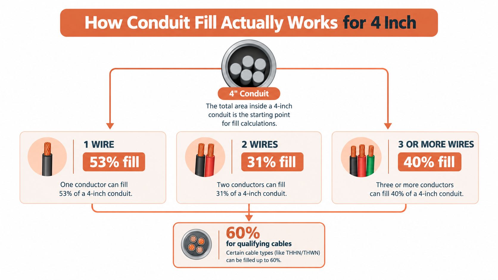
Conduit fill is based on the combined cross-sectional area of the conductors, not the trade-size label or a generic wire count. Under NEC Chapter 9, Table 1, the commonly applied maximum fill is 53% for one conductor, 31% for two, and 40% for three or more. A qualifying nipple no longer than 24 inches may use a 60% limit. (NEC Chapter 9 fill reference)
For a 4-inch EMT example, one published reference gives an internal diameter of 4.000 inches, a total internal area of 12.560 square inches, and an allowable area of 5.024 square inches at 40% fill for three or more conductors. The check is simple in principle:
Identify the exact raceway type and its interior area.
Add the actual cross-sectional areas of the conductors.
Compare the total conductor area with the allowable fill for the conductor count.
The example's arithmetic is 12.560 × 0.40 = 5.024 square inches. That allowable area applies to the stated EMT example and fill condition. A different 4-inch raceway can have a different interior area, and the conductor areas depend on the actual insulation and dimensions. (4-inch EMT conduit-fill example)
A published conductor-count chart is only a shortcut for the wire types and sizes it covers. Change the insulation, conductor dimensions, grounding conductors, cable assembly, or raceway material and the calculation needs to be checked again. A fill calculation also doesn't prove that the conductors can be pulled through the planned route.
For a visual walkthrough of the fill concept, use the video below alongside the project's actual conductor and raceway data.
Bends Pull Length and Pull Box Sizing
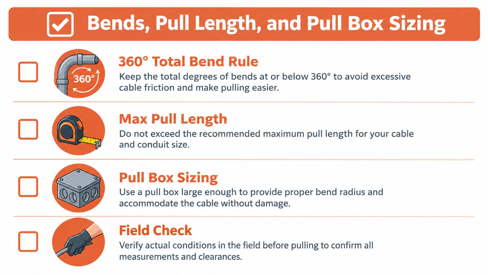
A 4-inch raceway can pass the fill calculation and still be a poor pull. The route's total bend, sweep radius, pull-point spacing, conductor arrangement, and pulling limits determine whether the installation is workable. For EMT, NEC Article 358.26 limits the cumulative bends between pull points to 360 degrees, equivalent to four quarter-turns. (EMT bend-limit reference)
Sweep radius deserves attention before the conduit is ordered. Utility requirements can differ by application: APS calls for at least a 36-inch sweep for three-phase 4-inch conduit, while communications systems may require a 48-inch minimum radius for 4-inch conduit. (APS underground construction guidance) The route still needs to be checked against the serving utility's current standard and the cable manufacturer's pulling limits.
For conductors 4 AWG or larger, NEC 314.28 sets minimum pull-box dimensions for angle and straight pulls, subject to applicable provisions and any listed, marked exception. A commonly applied angle-pull factor is six times the largest raceway trade size. For a 4-inch entering raceway, that factor gives 24 inches for the relevant dimension; the complete calculation must account for all entering raceways and the pull arrangement. (Pull-box sizing guidance)
A compliant fill calculation doesn't guarantee a practical pull. If the route combines large conductors, long pulls, and multiple bends, evaluate a pull point or a larger raceway before crews are committed to the installation. A 5-inch option may reduce pulling risk more effectively than relying on added lubricant or crew effort, but it still needs engineering and owner approval.
For a route that needs a directional fitting, verify its radius and raceway compatibility against the drawings and project standard before ordering a 4-inch conduit elbow.
Fittings Couplings Bodies and Supports for 4 Inch
A clean takeoff includes more than straight lengths. At this size, the wrong fitting can create a mismatch in raceway material, connection method, or usable pull geometry. Confirm that every accessory matches the specified conduit and the installation conditions.
Build the fitting schedule around the route:
Couplings and connectors: Match the raceway type and joining method. Threaded metal conduit needs compatible threaded fittings; EMT needs the specified EMT connectors and couplings; PVC needs compatible PVC fittings.
Conduit bodies: Identify whether the route calls for LB, LL, LR, T, or C bodies, and confirm the product is suitable for the conductor arrangement and access needs.
Pull and junction boxes: Size them for the actual conductors and entry directions, not just the nominal conduit size. Check the applicable pull-box rules and enclosure requirements.
Supports: Select hardware for the conduit material, installed conditions, and project requirements. Don't assume a support detail for a smaller raceway applies unchanged to a large run.
Expansion fittings: Include them where an exposed PVC route's temperature variation and manufacturer guidance warrant movement accommodation.
Firestopping: Identify rated wall and floor penetrations on the drawings and coordinate the approved firestop system with the actual conduit and opening.
The missed items are usually the ones that appear late: compatible locknuts or bushings, transitions, expansion provisions, supports, pulling accessories, and the right box or body at a change in direction. Add these to the BOM before release. That's less expensive and disruptive than resolving a mismatch during installation or inspection.
Underground Installation Specifics for 4 Inch
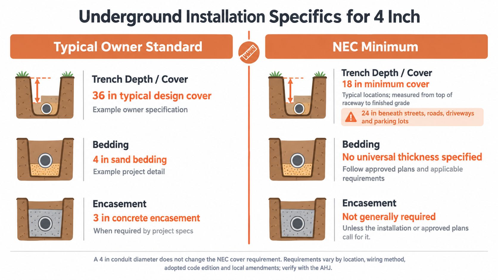
A 4-inch trade size does not set the burial assembly. The cited Alaska DOT raceway installation guidance calls for at least 50 millimeters of lateral clearance on both sides, 450 millimeters of cover below finished grade, and 50 millimeters of bedding beneath the conduit. Treat those figures as project requirements only where that specification applies. Loading, frost, nearby utilities, or occupancy may call for greater cover.
Set a clear field handoff before excavation. Hold trenching until bedding material, cover depth, encasement detail, and inspection hold point are signed on the same sketch, with conduit schedule and sweep radius noted by station. Record the serving utility's current sweep-table number and revision date in the submittal matrix before ordering elbows. Requirements vary by owner and application, so never carry a sweep detail from one project into another.
For field-cut PVC, make square cuts, deburr and ream the ends, and reject visibly deformed sections or sharp kinks. Form bends only by a manufacturer-approved method. Confirm whether the design specifies direct burial or concrete encasement before releasing material.
Exposed PVC needs support and allowance for thermal movement where required. Direct-buried and concrete-encased runs need different support approaches. Match the specified wall and application to available Schedule 40 PVC conduit options, then verify the complete assembly against the drawings and authority having jurisdiction. When a difficult pull threatens the installation, evaluate 5-inch conduit against the project requirements rather than forcing the nominal 4-inch choice.
Matching NEC Fill to Owner and Utility Standards
Passing an NEC fill check is necessary, but it doesn't settle the purchase. An owner, institution, serving utility, or authority having jurisdiction may specify the raceway schedule, material, burial assembly, sweep radius, labeling, and approval process. Those requirements can rule out a substitution even when the conductor area fits.
The project documents show why procurement needs to reconcile requirements rather than compare descriptions loosely. Northwestern's underground-duct guidance specifies 4-inch minimum conduit for primary/main feeders and telecom services. New York State underground-conduit specifications require project drawings to identify conduit sizes and schedules. APS specifies Schedule 40 NEMA TC-2 plastic conduit for certain 4-inch-and-smaller applications, while its sweep requirements depend on the system configuration. (Northwestern underground ducts and raceways guidance)
Put the requirements in a submittal matrix that the engineer, contractor, and distributor can all review:
Submittal item
Confirm before release
Raceway
Material, trade size, schedule or wall designation
A substitution should be reviewed against the whole matrix. A different material may change interior area; a different product may fail the owner's schedule or radius requirement. Do not approve a substitute based only on nominal size and conductor count.
Sourcing 4 Inch Conduit and Building the BOM
A usable BOM describes the product well enough for the supplier to source the right item and for the project team to verify it on delivery. Start with the raceway type and trade size, then add the schedule or wall designation, coating, applicable standard, certification, and length. For PVC, product documents may identify UL 651 and NEMA TC-2; verify the exact product. For EMT, confirm the applicable product requirements and project specification rather than carrying over a PVC standard.
Add every accessory needed to install and inspect the run: elbows, couplings, connectors, conduit bodies, boxes, supports, expansion fittings where required, firestop coordination, pull string, and pulling materials. Call out the owner's preferred manufacturers or approved-product requirements when the contract documents include them.
Shortages and long lead times can force an alternate product or route. That's when a distributor should compare the actual specification, not just locate something with a matching trade-size label. Ask for documentation showing the proposed product's material, dimensions, listing or certification, coating, and compatibility with the fittings and owner requirements. Get approval before releasing the substitution.
ATEK Distribution can assist with BOM review, sourcing hard-to-find conduit and fittings, coordinating manufacturer documentation, and evaluating approved alternatives when availability threatens a project schedule. For government and institutional work, align product submittals and procurement documentation with the contract requirements before the purchase order is released.
Quick Reference Checklist for 4 Inch Conduit
Use this checklist during takeoff, design review, submittal, and inspection. A complete answer to “Which 4-inch conduit?” should be visible in the project documents and purchase order.
Dimensions: Confirm the actual OD and ID for the selected product, not just the trade size.
Raceway type: Identify PVC, EMT, IMC, RMC, or PVC-coated rigid steel, including schedule or wall designation and coating.
Product requirements: Verify the applicable NEC article, product standard, certification, and manufacturer documentation.
Fill: Calculate using the correct internal area, conductor dimensions, and applicable fill percentage.
Boxes: Verify pull-box dimensions and entry arrangement against conductor size and pull direction.
Accessories: Include compatible fittings, couplings, supports, expansion provisions, firestop coordination, and pulling accessories.
Approval: Reconcile the design with owner, utility, engineer, and AHJ requirements before procurement.
For an industrial, utility, or government job, don't release the order until the raceway, fittings, and installation requirements agree across the drawings, submittal, and BOM. ATEK Distribution can help consolidate the package and document product alternatives for review.
Contact ATEK Distribution for help reviewing a 4-inch conduit BOM, sourcing hard-to-find raceway and fittings, or coordinating approved alternatives with project requirements. Share the conduit type, schedule, owner specification, and route details so the sourcing team can help confirm the package before release.
If you're staring at a BOM, a damaged field unit, or a substitution request that says “same plug, different vendor,” pin sleeve connectors are where the easy assumptions start to break down. The connector may fit, but that doesn't mean it belongs on the job, especially when voltage, phase, current, ingress protection, conductor type, and listing all have to line up before anyone signs off.
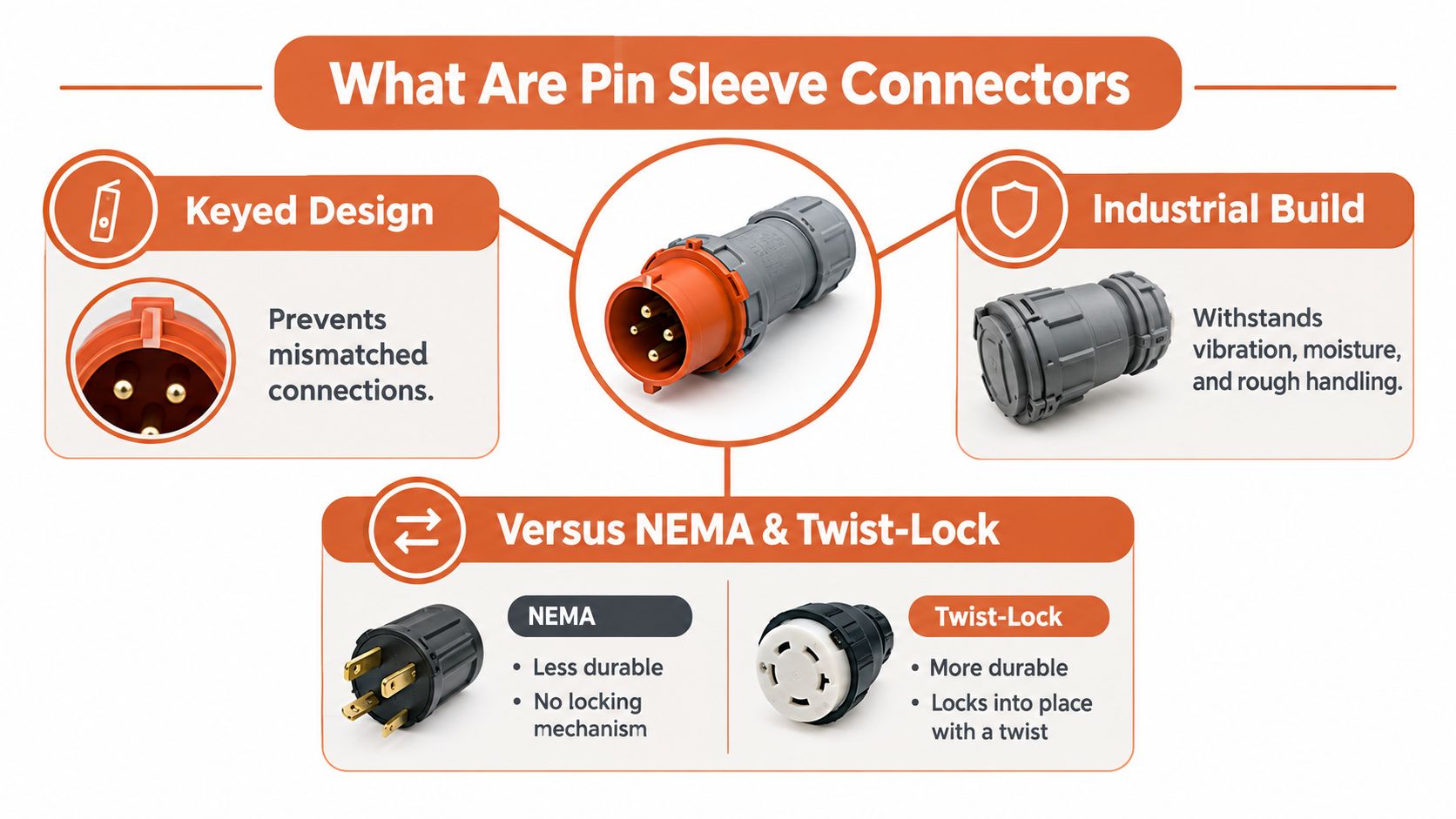
Pin sleeve connectors are rugged, keyed industrial plugs and receptacles built so the wrong connection is hard to make and easy to avoid. In practice, that means a pin, sleeve, and protective-earth arrangement designed for harsh service, not the loose-fit convenience of a light-duty cord cap.
Why the format exists
The value is mechanical and electrical keying. Each configuration is built to mate with only one matching socket arrangement, which helps prevent incompatible voltage, frequency, or phase connections. That's a big reason these devices show up on construction sites, in manufacturing, around utilities, in temporary power setups, and in entertainment power where people need deliberate incompatibility, not improvisation.
Where they sit compared with ordinary plugs
Standard NEMA devices and twist-locks solve some applications well, but they don't give you the same industrial keying structure or the same intentional separation between electrical systems. Pin sleeve connectors are chosen when the cost of a wrong connection is higher than the extra attention the device demands. They also bring the protective-earth connection into the design, which matters whenever the equipment is going to be handled, moved, or connected in the field.
Practical rule: if the job site has more than one voltage system, the connector family should do part of the safety work for you.
That's why specifiers treat this format as an industrial interface, not just a plug. The rest of the selection process is about proving that the connector family, rating, and listing all match the project, not just the opening in the wall.
Origins and the IEC 60309 Standard
The modern pin sleeve connector family traces back to the CEE 17 industrial plug-and-socket standard developed in the 1960s. It was published in Europe in 1966, entered the IEC framework as IEC 309 in 1969, and was later renamed IEC 60309. The United Kingdom aligned with the design as BS 4343 in 1968, which shows how quickly the format moved from a European industrial initiative into broader use. Historical overview of CEE 17 and IEC 60309
Why that history matters on real projects
That background isn't trivia. It explains why one connector family can be recognized as IEC 60309, pin-and-sleeve, or CeeForm depending on the market and application. The same industrial geometry carried through different regions because it gave buyers a stable way to specify dimensional, wiring, and safety requirements across multiple markets.
For procurement teams, that consistency is the whole point. If a project spans borders or uses mixed sourcing channels, a connector conforming to IEC 60309 can be evaluated against the same basic mechanical and safety expectations instead of being treated as a one-off custom item. That lowers substitution risk, but only if the full rating still matches the job.
What IEC 60309 covers
IEC 60309 covers plugs, socket-outlets, connectors, couplers, and appliance inlets for industrial applications. Its core design principle is compatibility control, not universal interchangeability. Mechanical and electrical keying helps keep incompatible systems apart, and that remains the reason the format is still recognized decades after its introduction.
A connector family stays relevant when buyers can repeat the same specification logic from one market to the next.
Ratings, Poles, and Color Clock Keying
Pin sleeve connectors are not one connector size with one current class. They span a broad electrical range, and the first mistake buyers make is treating the housing shape as the selection criterion. The key filter is a combination of voltage, current, poles, grounding, frequency, and enclosure protection.
Selection variables that actually matter
IEC technical summaries identify standard limits up to 1,000 volts AC or DC, 800 amperes, and 500 hertz. Common IEC current classes include 16 A, 32 A, 63 A, 125 A, and 200 A, while North American product families often include 30 A, 60 A, 100 A, 200 A, and 400 A versions. The system supports 2P+E, 3P+E, and 3P+N+E arrangements, so the same broad family can serve single-phase, three-phase, or three-phase-plus-neutral loads. Industrial and multiphase power plug summaries
Environmental protection is separate from electrical rating. Commercial devices are offered with ratings such as IP66, IP67, IP68, and IP69K, but that doesn't mean every product in the family carries every protection level. For outdoor, washdown, or temporary service, the actual assembly has to be checked, not assumed.
Color and clock position
IEC 60309 also uses housing color and clock-position keying to reduce mis-mating. Yellow commonly identifies 100 to 130 VAC, blue identifies 200 to 250 VAC, gray identifies 277 VAC, red identifies 380 to 480 VAC, and black identifies 500 to 690 VAC. The grounding contact sits at one of 12 clock positions in 30-degree increments, so voltage and frequency identity are confirmed both visually and mechanically. IEC 60309 color and clock keying reference
Voltage Range
Housing Color
Clock Position
Typical Use
100 to 130 VAC
Yellow
Varies by configuration
Lower-voltage industrial or temporary circuits
200 to 250 VAC
Blue
Varies by configuration
Common industrial single-phase and three-phase applications
277 VAC
Gray
Varies by configuration
Building and facility power systems
380 to 480 VAC
Red
Varies by configuration
General industrial distribution and machinery
500 to 690 VAC
Black
Varies by configuration
Higher-voltage industrial applications
What the color code doesn't do
Color helps, but it doesn't complete the spec. Current rating, phase arrangement, grounding/neutral configuration, ingress protection, and regional certification still have to be verified. A connector can look right and still be wrong for the load, which is why substitution review has to go deeper than physical fit.
UL 1682 vs IEC 60309 for North American Projects
North American buyers usually live in two worlds at once. On one side is the global IEC family, and on the other is the UL and CSA framework that governs many domestic projects. If you're building for a U.S. or Canadian site, the list on the submittal has to match the code path the AHJ and design team expect.
The North American listing path
For North American projects, specify pin-and-sleeve plugs, receptacles, power inlets, and cable connectors against UL 1682 and, where applicable, the harmonized CSA C22.2 No. 182.1 requirements. UL 1682 covers devices rated up to 800 A and 600 V AC or DC, including configurations with up to eight pilot contacts, for branch-circuit use with copper conductors in indoor or outdoor nonhazardous locations. UL 1682 scope summary
How it differs from IEC 60309
IEC 60309-1 and IEC 60309-2 are the principal framework for globally deployed industrial interfaces. They rely on dimensional and color keying, and the IEC framework extends to devices up to 690 V with current classes typically discussed up to 125 A or higher depending on product category and source summary. The point isn't that one standard is “better.” It's that the project market and approval path decide which listing belongs in the BOM.
Attribute
UL 1682 / CSA C22.2
IEC 60309-1 / 60309-2
Region
North America-focused
Global industrial use
Devices Covered
Plugs, receptacles, power inlets, cable connectors
Up to 690 V in the IEC framework, with defined current classes
Keying Method
Listing and product configuration details
Dimensional keying, color coding, clock position
Typical Use
North American branch-circuit projects
Multinational industrial and temporary power systems
What belongs in the submittal
Include the actual listing, the marked voltage and current, the pole and pilot-contact configuration, and the installation scope. Certification doesn't override the device's marked ratings, and it doesn't replace NEC or manufacturer instructions. If the project is U.S.-based, that paperwork matters as much as the connector body itself.
Conductor Compatibility and Assembly Markings
A connector spec that ignores the conductor is only half a spec. The device rating has to align with the cable, the termination method, and the way the assembly is built.
Read the markings as a full assembly check
UL 1682 expects copper conductors, and that single detail already rules out a lot of lazy substitutions. The listed wire range, conductor size, cable diameter range, strain relief, and temperature rating all have to fit the exact assembly. An ampere marking tells you the family, but it doesn't prove the terminal, jacket, or entry system will accept the actual cable on site.
That's why a connector from the right family can still fail a submittal. Fine-stranded and class B conductors can behave differently at termination, and the assembly may need a specific ferrule or termination approach to stay within the listing. If the connector body is certified but the cable entry isn't, the whole assembly is still wrong.
For cable terminations that need clean conductor preparation before the plug or inlet is built, a practical reference like this ferrule crimp guide can help crews avoid sloppy end prep. On the cable side, a product set such as 22kW cables at EVChargers.eu is a useful reminder that the conductor side of a power connection is part of the specification, not an afterthought.
What to verify before approval
Conductor material: Confirm the listing matches the actual conductor material, especially on branch-circuit work.
Wire size range: Check the terminal's accepted range, not just the amp rating stamped on the housing.
Cable entry: Match the jacket diameter to the strain-relief window.
Temperature rating: Make sure the conductor insulation and connector terminal ratings work together.
Termination method: Verify ferrules, lugs, or direct terminations only where they're explicitly accepted.
A connector can be the right current class and still be a bad fit if the wire range or strain relief doesn't match the cable on the truck.
Installation Practices and Field Safety
The best-listed connector still fails if it's installed carelessly. Torque, strain relief, and the way the assembly is handled on the jobsite decide whether the device performs as intended.
What disciplined installation looks like
Start with the manufacturer's listed torque values, not a feel-based tighten-and-hope method. Then match the cable jacket and conductor diameter to the listed strain-relief range, because a connector body that grips the wrong cable size can loosen, overheat, or fail mechanically under vibration. Wiring strain relief reference
The assembly also has to be seated and locked correctly. If the device is tested for load make-and-break, that doesn't mean an installer should treat live disconnection as routine practice. De-energize before unplugging unless the manufacturer and the application specifically allow otherwise under the applicable rules.
Code and enclosure checks
UL certification authorizes use only within the device's marked ratings. It doesn't override the NEC, manufacturer wiring instructions, or local code requirements. For washdown and outdoor service, confirm the IP rating on the complete mated assembly, not just on the catalog line for the connector family.
The field failures that show up again and again are simple: loose terminals, wrong cable size, damaged locking features, and assemblies left half-seated. Those are avoidable when the install crew treats the connector as a controlled electrical interface, not just a rugged plug.
Diagnosing Overheating Before Failure
A connector can still pass power and still be unsafe. That's the part most maintenance programs miss, because “it still works” is not the same thing as “it's thermally healthy.”
Why heat is a warning, not a byproduct
Contact resistance in connectors is measured in milliohms, so normal heating is usually small. When a connector runs hot, the problem is usually excessive current or a contact defect that creates a localized hot spot. A loose connection is especially risky because it can arc and heat without enough overcurrent to trip upstream protective devices. Electrical-connection failure guidance
A practical inspection workflow
Inspect visually. Look for discoloration, contamination, looseness, damaged sleeves, or insulation deterioration.
Compare temperatures. Check the connector body against the attached conductor under representative load.
Use infrared thermography. A thermal scan helps find hot spots that aren't obvious during a quick walkdown.
Verify the termination. Recheck torque and locking condition if the temperature pattern looks abnormal.
Repair or replace. If the connector is running hotter than the conductor, treat that as a functional failure.
Functional rule: a connector hotter than its conductor has already failed the maintenance test, even if the circuit is still live.
The threshold that matters
Thermal inspection is separate from upstream protection. A breaker that hasn't tripped doesn't prove the connection is healthy. Maintenance teams often use 90°C or the insulation limit as the lower threshold for corrective action, but the true trigger is the temperature behavior of the assembly under load. The point is to catch degradation before it becomes a burn-up, not after.
Compatibility Matrix and Substitution Review
Mechanical fit is the starting point, not the approval decision. Two connectors can mate cleanly and still fail the project because one of the hidden variables doesn't match.
What belongs on the review sheet
Substitution review should capture voltage and frequency, phase and pole count, ampacity, grounding and neutral configuration, ingress protection, hazardous-location suitability, cable type and termination method, temperature, duty cycle, and local code approval. That list is long because the project risks are real. A plug that fits the receptacle can still be rejected if it fails the environmental spec or the wiring method.
If the vendor only proves that the plug fits, that's not enough. If the alternate has the right amperage but the wrong grounding clock, the wrong cable entry, or the wrong environmental rating, it's still the wrong part. That's the kind of failure that shows up late, after the shipment is already on the dock.
A clean review package beats a rushed field correction every time.
Quick Reference for Specifying and Sourcing
The fastest way to specify pin sleeve connectors is to stop thinking of them as one item and start treating them as a controlled assembly. Pick the standard first, then the electrical rating, then the environment, then the conductor and termination details.
Quick decision path
Choose the standard: Use UL 1682 / CSA C22.2 No. 182.1 for North American projects, or IEC 60309 where the global industrial format is acceptable.
Match the keying: Confirm color and clock position before approving a replacement.
Verify the load path: Check voltage, current, poles, grounding, and frequency together.
Check the cable side: Confirm conductor material, wire range, strain relief, and temperature rating.
Confirm the enclosure: Don't infer IP performance from the connector family name.
Review the paperwork: Installation instructions, product markings, and listing documentation belong in the submittal set.
Good sourcing habits
When a project is short on time or the exact part is hard to find, the substitute still has to pass the full compatibility check. A generic “same family” match won't help if the cable entry, rating, or certification is off. For cable and cord sourcing support that fits into a broader industrial BOM review, wire cords and cables is a useful category to keep in mind during procurement planning.
The best alternate part is the one that survives both the spec review and the field install.
If you're comparing replacements, building a submittal, or trying to keep a mission-critical job moving, ATEK Distribution can help with BOM review, hard-to-source pin sleeve components, approved alternatives, and compliance documentation. Visit ATEK Distribution to request sourcing support and keep the project moving with the right electrical components.
You're at the takeoff stage with a spreadsheet full of part numbers, a ceiling plan showing long communications runs, and an inspection checklist that will scrutinize every transition. The question looks simple: which Caddy J hook should support the bundle? In practice, the answer depends on two separate checks, cable-fill capacity and structural load. Confusing them is how a hook can meet a published cable count yet still exceed its allowable weight.
A Caddy J hook is a non-continuous pathway support. It carries communications cable while preserving cable geometry, bend radius, and access for future service. That makes it different from a cable tie or narrow-base bridal ring, which can kink, overbend, or crimp high-performance cable, and different from cable tray, which provides a continuous pathway.
For crews working on structured cabling, audiovisual systems, PoE, coaxial, fire alarm, or control wiring, the hook isn't just a commodity fastener. Hook diameter, retainer configuration, mounting method, cable schedule, fill basis, and static-load rating all belong in the specification. A resource on fiber-optic network design and construction can also help teams coordinate pathway planning before installation begins.
The support geometry and spacing standards determine the starting point for that specification.
A Caddy J hook supports a cable bundle at intervals instead of enclosing the entire route. Its curved profile gives installers a defined resting surface and helps maintain the cable's intended bend path through horizontal runs, transitions, and equipment approaches. The support should carry the bundle without crushing it or forcing it into a smaller radius than the cable manufacturer permits.
Cable ties and bridal rings solve a different problem. They can secure a bundle, but excessive tension or a narrow contact point can deform Category 6A, fiber, or other high-performance communications cable. A J hook leaves the bundle supported without turning the support into a compression point.
Cable tray remains the better comparison when the route requires a continuous pathway, dense cable management, or a defined route for a growing quantity of services. J hooks are often efficient for distributed communications runs where the building structure provides suitable attachment points and the bundle can be supported at planned intervals.
Practical rule: Treat the hook as a rated cable-support component, not as a convenient place to hang cable.
What belongs on the takeoff
A useful takeoff records more than a nominal hook size. At minimum, identify:
Cable type: Separate Category 5e, Category 6, Category 6A, fiber, innerduct, PoE, and mixed-media bundles.
Outside diameter: Use the actual cable schedule or manufacturer data, not a generic assumed diameter.
Bundle geometry: Determine whether one bundle can remain together without exceeding fill or bend-radius limits.
Attachment method: Confirm whether the hook will mount to a wall, ceiling structure, joist, or threaded rod.
Environmental location: Establish whether the pathway is in an air-handling space and whether the selected product has the required listing.
This information gives the engineer and installer a defensible basis for product selection. It also gives the inspector something more useful than a box label or a “typical” cable count.
Bend Radius and Pathway Standards That Drive J Hook Selection
Bend radius comes before the model number. For copper cabling, the cited TIA-568.0-E guidance uses a minimum bend radius of four times the cable diameter. A typical Category 6A cable with an approximate 0.25-inch diameter therefore calls for at least a 1-inch bend radius at an appropriate J-hook support, as documented in the nVent CADDY CAT HP product guidance.
Fiber-optic cable requires substantially more clearance. The cited standards guidance specifies a minimum bend radius of 20 times the cable diameter, so a hook suitable for a copper bundle shouldn't automatically be approved for fiber. The actual cable manufacturer's requirements and the project specification govern where they are more restrictive.
The standards that inform the selection
The product documentation identifies TIA TSB-184-A and ISO/IEC TR 21925 as relevant guidance for cable support and bend-radius considerations. TIA-568.0-E establishes the copper bend-radius relationship, while the support and pathway guidance helps engineers translate that requirement into hook geometry, routing, and installation practice.
The practical selection sequence is straightforward:
Confirm the largest cable diameter in the bundle.
Apply the applicable bend-radius rule.
Select a hook whose support geometry preserves that radius without crowding the bundle.
Confirm that the cable can enter, rest in, and leave the hook without a sharp transition.
A 1-inch hook can be a practical starting point for smaller copper cable, while 1.5-inch to 2-inch supports may be more appropriate for larger Category 6A bundles or mixed pathways. Fiber runs commonly require the larger end of a product family because their bend-radius requirement is wider.
Excessive bending can impair transmission performance, increase insertion loss, or damage the cable. For broader structured cabling advice from Networking2000, coordinate pathway planning with the cable schedule rather than selecting supports after the route has already been crowded.
CAT HP J Hook Family and Where Each Size Fits
The CAT HP family is easier to evaluate as a progression than as a list of isolated SKUs. Start with the cable geometry and bundle size, then check the support's published fill capacity and structural rating independently.
The CAT16HP provides a 1-inch support diameter. The CAT32HP provides a 2-inch support diameter. Both are listed with a 60 lb static load rating, so the larger hook gives more cable area without automatically increasing the amount of weight the attachment can carry.
CAT16HP vs CAT32HP at a Glance
Feature
CAT16HP (1 in)
CAT32HP (2 in)
Support diameter
1 inch
2 inches
Static load rating
60 lb
60 lb
Category 5e capacity at 70% fill
20 cables
90 cables
Category 6 capacity at 70% fill
15 cables
60 cables
Category 6A capacity at 70% fill
10 cables
35 cables
Typical selection logic
Smaller bundle and tighter support geometry
Larger bundle area and greater cable count capacity
Attachment options
Wall, ceiling, threaded rod, subject to approved installation
Wall, ceiling, threaded rod, subject to approved installation
The published capacity values are calculated at a 70% fill rate, and they aren't universal answers for every cable. Actual outside diameter, jacket construction, bundle arrangement, future additions, and the attachment structure can change the practical selection.
CAT HP models also provide UL 2043 compliance for air-handling and plenum spaces, subject to project verification and installation requirements. The product family supports wall, ceiling, and threaded-rod attachment methods, but the selected mounting method still has to suit the substrate and load.
A submittal should identify the exact part number, diameter, cable type, mounting method, and environmental requirement. CAT HP is one available family, not a substitute for reviewing the entire cable-support design.
Cable Count Versus Static Load The Two Capacity Checks
A Caddy J hook has two independent limits. Cable-fill capacity describes how much cable area fits within the manufacturer's fill assumption. Static load rating describes how much weight the hook assembly can carry. One does not replace the other.
For the 1-inch CAT16HP, the published figures at a 70% fill rate are 20 Category 5e, 15 Category 6, or 10 Category 6A cables. For the 2-inch CAT32HP, the corresponding figures are 90 Category 5e, 60 Category 6, or 35 Category 6A cables, also at a 70% fill basis, as shown in the CAT HP product data.
Both models carry a 60 lb static load rating. Increasing hook diameter can increase the available cable area, but it doesn't raise the allowable structural load.
A count that fits can still weigh too much
The same issue appears in larger supports. Published data for 3-inch CADDY J hooks increases capacity to 150 Category 6 cables and 80 Category 6A cables, while the listed static load remains 60 lbin the manufacturer-related product data. The cable count rises, but the load ceiling does not.
Use this workflow before approving a hook:
Identify the cable outside diameter and weight. Use actual product data for each cable type.
Apply the manufacturer's fill basis. Keep the bundle within the stated 70% fill assumption where that basis governs the published count.
Calculate the combined weight. Include the cable bundle, not just the number of cables.
Check the hook rating and attachment structure. The support and the building attachment must both carry the load.
Reserve room for moves, adds, and changes. A pathway installed at its limit leaves no practical margin.
Divide the bundle or change the pathway when either the fill or load limit is approached.
Port count is not a cable-support calculation. A “typical” value is not a submittal basis. The safe answer comes from the actual cable schedule, the manufacturer's assumptions, the structural attachment, and the expected future use of the pathway.
J Hook Spacing Intervals and Why 5 Feet Is a Ceiling
A five-foot interval gives a horizontal J-hook route its maximum commonly permitted span, not a default layout for every cable bundle. The cited TIA-569-C.9.7 and EN 50174-2 guidance for CAT HP installations identifies 5 feet, or 1.5 meters, as the upper limit as documented in the applicable specification sheet. Project specifications can require closer supports.
High-performance data and fiber-optic runs may need support at 3-foot spacing to control sag and preserve bend management, according to J-hook installation guidance. The shorter interval also helps where cable weight or route geometry makes a five-foot span impractical.
Set supports closer together at turns, vertical drops, equipment entries, risers, fire-rated penetrations, and points where several cables converge. These locations introduce more bending and movement than a straight, lightly loaded horizontal run.
Before releasing the layout, check four separate conditions:
Fill: Keep the bundle within the hook's published cable capacity and stated fill basis.
Structural load: Confirm the combined cable weight stays below the hook's static rating and the attachment capacity.
Sag and bend control: Support the cable often enough to maintain its required bend radius and avoid an obstruction.
Project requirements: Apply any specified 4-foot to 5-foot spacing or added supports, even when the nominal maximum is not exceeded.
Heavier PoE bundles, fiber, mixed media, vibration, and seismic conditions can all justify shorter intervals. Calculate support quantities from the cable schedule and add supports at transitions. Dividing route length by five feet alone can undercount the hardware and leave either the fill check or the structural-load check unresolved.
Substrate and Attachment Rules Every Installer Must Follow
A J-hook layout can pass its cable-fill check and still fail structurally. Verify both conditions separately: the hook must hold the cable bundle within its published capacity, and the attachment must transfer the combined load into a suitable building element.
Use the approved design and fastening method for the actual substrate. Structural framing or an appropriate joist connection can provide that support. A ceiling surface may be convenient without being designed to carry communications cable.
Choose the substrate before the fastener
Do not attach J hooks to:
Ceiling-grid wire or grid components: They are not intended to carry communications-cable loads.
Conduit or piping: Electrical conduit, sprinkler pipe, gas pipe, and plumbing serve other systems and do not replace structural support.
HVAC ductwork: Ductwork is not an approved support point for the hook and bundle.
Cable tray or ladder rack: These are pathway systems, not automatically suitable substrates for suspending another support.
Unsupported surfaces: Correct any condition that cannot carry the combined hook and cable load before installation.
Orientation also affects the installation. For overhead mounting, keep the hook level so the bundle bears evenly. For vertical mounting, point the opening upward or sideways to retain the cables. Before rough-in inspection, confirm the substrate, fastener, hook seating, orientation, and cable route. A light bundle does not make ceiling-grid wire or another prohibited surface acceptable.
Plenum, Air Handling, and Power Separation Requirements
A ceiling void used for air handling changes the approval checks for a J hook. Confirm that the selected product is listed for that environment, then verify the cable rating, attachment method, and project standard. CAT HP models carry UL 2043 compliance for air-handling and plenum spaces. That listing addresses the support's fire-performance suitability, not every installation decision.
Power separation requires its own review. Low-voltage cables may share a ceiling space with branch circuits and other services, but the adopted electrical and communications standards govern the required distance, routing, or barrier. A plenum-rated support does not permit arbitrary proximity to power conductors.
Use the submittal to record three distinct approvals:
Support listing: Identify the J hook and confirm its documentation covers the air-handling space.
Cable suitability: Confirm that each communications cable has the rating required for the environmental location.
Power separation: State the distance or barrier requirement and identify the project standard that establishes it.
Treat the published listing and the cable-fill figure as separate from structural capacity. The hook still needs an appropriate substrate and attachment method, while the bundle must stay within the manufacturer's stated cable and load limits.
For healthcare, education, government, and mission-critical facilities, include these records with the wider data and telecommunications infrastructure category procurement package. The project engineer and authority having jurisdiction determine which requirements apply.
Putting It Together A J Hook Selection Workflow
A dependable selection workflow converts the cable schedule into a documented installation decision, with separate checks for pathway fit and support capacity.
Start with the cable schedule
List every cable type in the proposed bundle. Record its outside diameter, required bend radius, and estimated weight. A mixed Category 6A and fiber run in a commercial corridor should not be sized from the Category 6A count alone. Fiber construction may require more bend clearance, even when its cable count is low.
Select the smallest hook diameter that preserves the required radius for every cable in the bundle. If the fiber needs more room than the copper, choose a support that accommodates both or place the media in separate pathways.
Run the two capacity checks
First apply the manufacturer's cable-count basis at 70% fill. Then calculate the actual bundle weight against the hook's static-load rating. These are different checks. A published cable count answers the area question, while the load calculation addresses the support and attachment. If either limit is approached, divide the bundle or select a larger support. A larger hook adds cable area, but it does not automatically raise the static-load rating.
Set supports no more than 5 feet, or 1.5 meters, apart, using the CAT HP specification sheet cited in the Spacing section above and the applicable TIA-569-C.9.7 and EN 50174-2 guidance. Tighten the layout at transitions, risers, equipment entrances, heavy concentrations, vibration or seismic conditions, and locations where cables need closer bend control.
Finish with the installation review
Verify that each attachment reaches the building structure or an appropriate joist connection. Confirm plenum suitability, power separation, hook orientation, and the fastening method's capacity.
A practical takeoff record should include:
Cable schedule and outside diameters.
Bend-radius basis and selected hook diameter.
Cable-fill and static-load calculations.
Spacing plan, including added supports at transitions.
Substrate, fastener, and mounting method.
Environmental listing and power-separation review.
Product data and approval status.
The cable management category helps organize related pathway components. Keep each selection step with the submittal so the installation basis is clear during review and inspection.
When J Hooks Stop Working and Cable Tray Takes Over
J hooks and cable tray aren't competing answers for every route. J hooks work well when bundles remain distributed, attachment points are available, and the pathway doesn't need a continuous base. Cable tray becomes more practical when density, expansion, or coordination requirements make individual supports difficult to manage.
Watch for these crossover signals:
Fill repeatedly approaches the limit: Larger hooks still reach the applicable fill basis across multiple routes.
Support quantities grow rapidly: The takeoff needs more and more individual attachment points to maintain control.
The ceiling becomes congested: Plenum space, transitions, and separation requirements become the binding constraints.
Future capacity matters: Moves, adds, and changes would consume the remaining practical room in the J-hook layout.
The specification calls for tray: A project requirement can settle the pathway choice regardless of the initial takeoff preference.
Adding a larger hook doesn't solve a structural load problem, and adding supports doesn't create a continuous pathway. When cable density and route coordination dominate the design, a tray system can provide a more controlled installation basis. The appropriate conduit, raceway, and cable support category can support evaluation of both approaches.
A coordinated procurement plan can stage J hooks and tray in the same shipment. That keeps the pathway decision tied to the engineering requirement rather than to whichever component arrives first.
Procurement and Submittal Notes for Caddy J Hooks
A defensible Caddy J hook submittal identifies the exact part number, hook diameter, mounting method, cable type, cable outside diameter, fill basis, and static-load rating. It should also show how the selected support fits the approved spacing, substrate, environmental, and separation requirements.
Don't approve an alternate because its cable count looks higher. A substitute may meet the cable-count requirement while exceeding the 60 lb static-load rating, using a different fill assumption, or requiring an attachment method that the project doesn't permit. Verify the product data and cable schedule together before accepting a substitution.
ATEK Distribution can assist with BOM review, hard-to-source components, manufacturer coordination, approved alternatives, and compliance documentation when shortages or lead-time changes threaten a mission-critical electrical project. The team can also help consolidate sourcing requirements so the J-hook decision remains aligned with the wider cable-management package.
ATEK Distribution helps contractors, engineers, facilities teams, and procurement professionals source Caddy J hooks, cable tray, and related electrical infrastructure with technical submittal support and approved-alternative review. Visit ATEK Distribution to request sourcing assistance, BOM support, or a project-specific quote.