
The most common mistake with 500 kcmil aluminum cable is treating the 90°C insulation rating like a blank check. It isn't. The conductor may be able to survive a higher temperature column, but the actual feeder design is usually limited by terminations, installation method, and the equipment that has to accept the conductors without overheating or failing inspection.
That's why this size shows up so often in real feeder and service-distribution work. 500 kcmil aluminum sits in the large-conductor range used for commercial and industrial power distribution, and its published ampacity values make sense only when you match them to the terminal rating, raceway layout, and ambient conditions, not just the highest number on the chart. In practice, the design conversation is never “what can the cable theoretically carry,” it's “what can the full installed system support without creating a maintenance or compliance problem.”
Table of Contents
- The Reality of 500 kcmil Aluminum Cable Sizing
- Navigating Ampacity and the 75°C Termination Rule
- Applying Derating Factors for Real Installations
- Physical Properties and Job Site Handling
- Voltage Drop and Fault Duty Considerations
- Procurement Resilience and Supply Chain Risk
- Executing Your Cable Procurement Strategy
The Reality of 500 kcmil Aluminum Cable Sizing
A lot of spec sheets encourage a simple reading, if the insulation is rated for 90°C, use the 90°C ampacity. That shortcut causes trouble fast. The conductor might be capable of that thermal class, but the lugs, breakers, switchgear, and other terminations often set a lower limit that governs the actual feeder design.
Why the cable size matters more than the chart headline
Published NEC-based references list 500 kcmil aluminum conductors at 260 A at 60°C, 310 A at 75°C, and 350 A at 90°C under standard conditions, and a 2025 NEC-reference table shows 256 A, 304 A, and 344 A depending on insulation column, which points to the same practical reality, this is a large feeder conductor, not a magical free-pass wire (wire ampacity reference). Those values place the conductor squarely in the feeder and service-distribution range for commercial and industrial systems.
Practical rule: the conductor's insulation rating and the termination rating are not the same thing, and the lower one usually governs.
For engineering teams, that distinction matters more than the absolute top-line ampacity. If you're planning around the 90°C column without checking equipment markings, you can overspecify the cable or, worse, build a feeder that looks right on paper and fails at the terminal. The historical significance of NEC ampacity tables is that they standardized safe conductor selection across North America, so the skill that matters is reading the table the way inspectors and field electricians do, not the way a catalog headline does.
What this means in procurement terms
Procurement teams should treat 500 kcmil aluminum cable as a specification item, not a commodity size. The cable choice is only valid when it fits the terminal temperature class, the installation method, and the available cable routing space. That is where a BOM review catches expensive mistakes before material is ordered and scheduled.
Navigating Ampacity and the 75°C Termination Rule
The 75°C column is where most project teams end up, because that's often where the terminations land. The conductor may be rated for 90°C insulation, but equipment terminations commonly force the design back down to the lower practical column. That's why 500 kcmil aluminum is frequently treated as a roughly 300 A-class conductor in real feeder work, not just as a 350 A cable.
How the temperature columns actually behave
Independent reference tables list 500 kcmil aluminum at 260 A (60°C), 310 A (75°C), and 350 A (90°C), while manufacturer data for a related low-voltage cable shows DC resistance near 0.116 Ω/km at 20°C and ampacity around 310 A at 75°C and 350 A at 90°C in raceway or conduit applications (ampacity and resistance reference). In free air, the same size can be rated higher, with one manufacturer listing 545 A at 30°C ambient in a different installation condition, which shows how much installation environment changes the number.
| Temperature Rating | Base Ampacity (Amps) | Typical Application Constraint |
|---|---|---|
| 60°C | 260 A | Lower terminal or equipment temperature class |
| 75°C | 310 A | Common termination limit in feeders and services |
| 90°C | 350 A | Cable insulation limit, not always the system limit |
That table is the key to avoiding bad assumptions. The conductor can be perfectly fine at 90°C from an insulation standpoint, but if the breaker, lug, or switchboard is marked for 75°C, then the design has to respect the 75°C value. That's the bottleneck often overlooked.
Where overspecification sneaks in
The counterintuitive problem is that 500 kcmil aluminum is sometimes selected because someone wants headroom for a 90°C number, but the usable capacity collapses once the terminal rule is applied. In other words, the chart can make a conductor look larger than the actual feeder demand, and then the project team discovers that a smaller conductor class or a parallel arrangement would have been a cleaner fit.
A feeder doesn't fail because the cable had too little theoretical ampacity. It fails because the installed system couldn't use the ampacity that was on the paper.
For contractors and engineers, that means reading conductor selection as a whole-system exercise. For procurement, it means confirming the exact termination class and installation format before release, because swapping cable after rough-in can cost more than the material delta ever saved.
Applying Derating Factors for Real Installations
A base ampacity number is only the starting point. Real installations change the thermal picture immediately, and 500 kcmil aluminum cable is no exception. Ambient heat, continuous loading, and conductor grouping all cut into usable ampacity, which is why the same size can work in one project and be wrong in another.
The conditions that change the answer
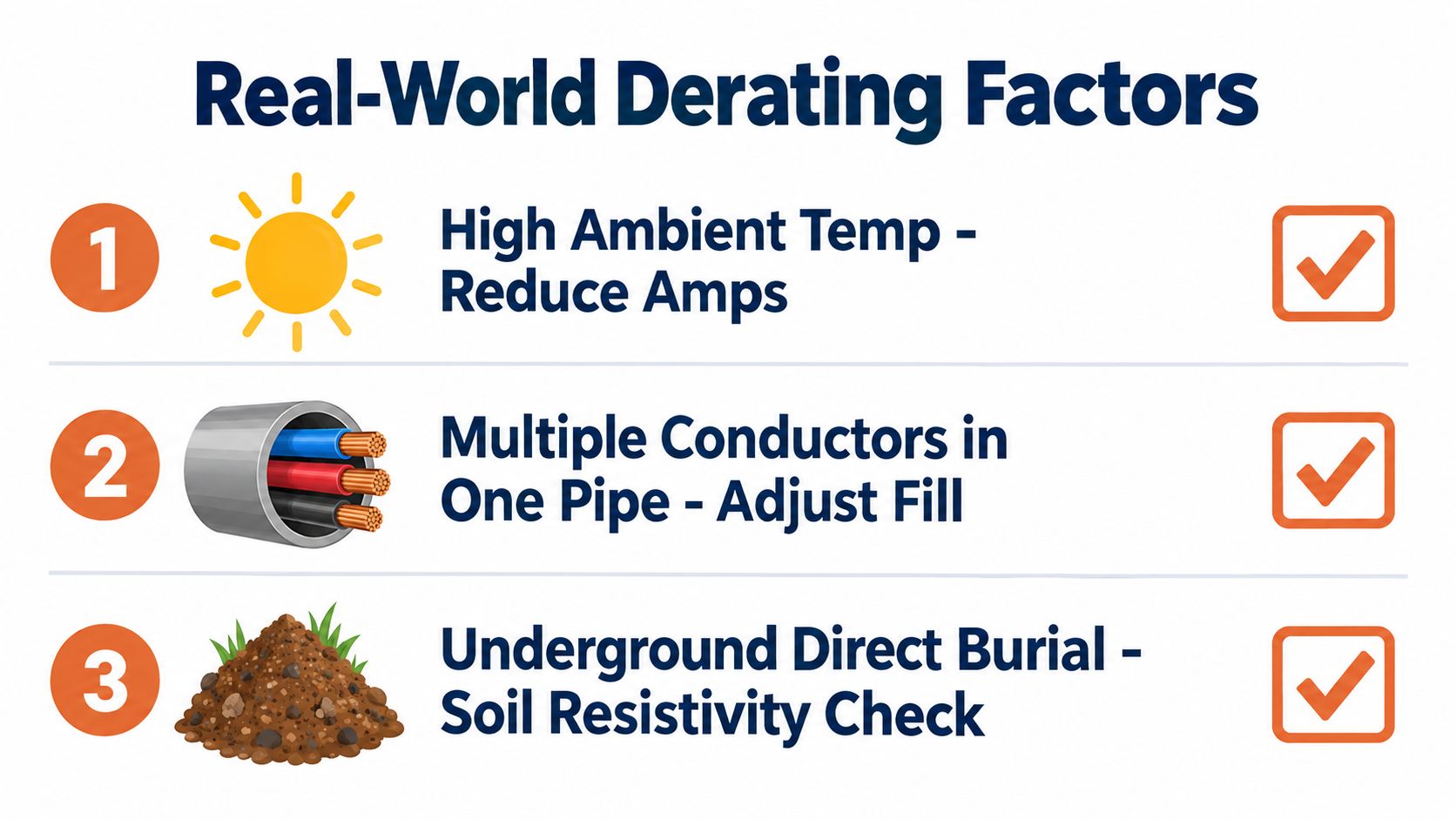
The most common derating variables are straightforward, even if the calculations aren't. Hot ambient conditions, tight raceway fill, and underground burial all reduce heat dissipation, which means the conductor reaches its temperature limit sooner. In practical terms, that can push a feeder that looks adequate on a desk into a marginal installation once it's in a congested duct bank.
Field rule: if the installation traps heat, the allowable current falls. The cable doesn't care what the catalog says.
A 500 kcmil aluminum feeder may be acceptable in free air and still be undersized in a hot underground duct or tightly bundled raceway. That's why designers have to account for continuous-load expectations, conductor count in the raceway, and the ambient temperature at the actual installation point. The chart value is not the finished answer, it's the input.
The linked video below is useful for crews and project managers who need a fast visual reminder of how those environmental variables interact in the field.
How to keep the design honest
The safest approach is to derate first, then verify the load. That sounds basic, but it's where many late-stage submittal corrections come from. If you size to a headline ampacity and only later discover a hot mechanical room, a long burial run, or multiple current-carrying conductors in one pipe, the installation can turn into a change order.
The same logic applies to continuous load assumptions. If the feeder serves a duty cycle that runs hot for long periods, the cable has to be selected for the installed condition, not the ideal one. For project teams, that's a design review issue. For procurement, it's a reason to hold the order until the routing and termination details are locked.
Physical Properties and Job Site Handling
A catalog ampacity does not tell the crew whether a 500 kcmil aluminum cable will fit the route, survive the pull, or enter the termination without rework. Cable weight, outside diameter, bend radius, and pulling tension can control the installation schedule long before electrical calculations become the problem.
Medium-voltage builds are much heavier than the name suggests
Published data for a Nexans 15 kV XLPE design lists a 253 mm² conductor cross-section, 18.74 mm conductor diameter, 34.27 mm nominal outer diameter, approximately 1,474.99 kg/km weight, and a 535 A current rating in air at 40°C, with 370 A buried in duct at 20°C (Nexans 15 kV product data). A higher-voltage build for the same nominal conductor size can weigh substantially more while retaining a similar air rating because insulation and shielding add material.
That difference affects reel selection, unloading equipment, tray supports, and the pulling calculation. Confirm the cable's actual shipping weight and outside diameter before releasing the installation plan.
Construction changes more than just the outside diameter
One manufacturer sheet lists 37 strands for a 500 kcmil medium-voltage conductor. Another 500 kcmil design has an outer diameter of 38.29 mm, while a different insulation system reaches 40.67 mm (conductor construction data). Those dimensions affect conduit fill, roller selection, bend geometry, and the space available inside a termination enclosure.
ACAR 500 kcmil conductors are typically lighter and stronger than standard builds, so confirm the alloy family and minimum breaking load against the pulling plan before release. Do not substitute a conductor family based only on the shared kcmil designation.
If the reel arrives late or the pulling setup is improvised, damage can occur before the first termination is made.
Prepare the route before delivery. Verify reel orientation, pulling tension, allowable bend radius, lubricant compatibility, roller spacing, and support points. Termination lugs and equipment entry points also need a dimensional check. A focused guide to wiring strain relief can help when strain control and termination hardware are part of the scope. These checks are practical schedule protection, not paperwork.
Voltage Drop and Fault Duty Considerations
Ampacity alone does not make a feeder usable. Long runs with 500 kcmil aluminum cable still have to hold voltage at the load, and they still have to survive the fault current until the protection clears. Those two checks, voltage drop and fault duty, are where a design often gets changed late.
Resistance and reactance accumulate over distance
Manufacturer data for a 500 kcmil aluminum medium-voltage cable reports AC resistance at 60 Hz and 90°C of about 0.149 Ω/km, phase reactance near 0.15 to 0.17 Ω/km, and short-circuit capability of 29.3 kA for 1 second (MV cable electrical data). Those figures matter because voltage drop comes from both resistance and reactance, and long feeders magnify both effects.
The impact shows up in motor starting, equipment tolerance, and control stability. A conductor that passes ampacity checks can still cause trouble in service if the route is long enough. At that point the options are straightforward, shorten the run, upsize the conductor, or parallel conductors.
Fault withstand is part of the design, not a footnote
Fault duty has to be checked against the prospective fault current and the clearing time of the protective device. If the cable cannot survive long enough for the breaker or fuse to open, the design is not complete.
For plant work, coordinated fault response matters as much as the cable itself. A useful adjacent reference is plant-level electrical fault detection, because cable sizing and protection settings are tied together in actual installations, not handled as separate tasks.
The cable does not need to survive forever, it needs to survive until the protection opens.
Long feeders often trigger a second review for that reason. The correct fix may be a larger conductor, a shorter route, or a protection change. If impedance and fault duty are left until late submittals, the field crew usually pays for it.
Procurement Resilience and Supply Chain Risk
A lot of buying decisions still treat 500 kcmil aluminum cable as a simple cost-per-foot line item. That overlooks a significant risk. Availability now depends on upstream rod supply, utility electrification demand, and project timing, so the right cable can be hard to secure exactly when the crew is ready.
Availability is becoming part of the specification
Recent industry reporting says Hydro and Nexans signed a five-year agreement covering about 85,000 tonnes of low-carbon aluminum wire rod from 2026 to 2030, which points to a clear shift toward cleaner upstream supply for cable manufacturing (aluminum wire market reporting). The number itself matters less than the signal. Major manufacturers are planning around material flow, not just finished-product demand.
Market pressure is broader than one supply agreement. A 2026 Light Metal Age market report projects the global aluminum wire and cable market at $38 billion by 2026, tied to HVDC interconnectors, hyperscale data centers, and renewable utility connections (market report). Even if your job is outside those sectors, that demand affects lead times, approved alternates, and what is available in the channel.
Why procurement teams need a risk lens
Schedule protection is the issue. Large-gauge aluminum conductor programs can slip because of long manufacturing windows, unavailable insulation or jacket systems, or a late decision to accept an approved alternate. Teams that already reviewed alternates, submittals, and compliance paperwork are the ones that keep moving.
That kind of planning is where a sourcing partner helps. ATEK Distribution can support BOM review, manufacturer coordination, compliance documentation, and harder-to-source cable configurations, which matters when a specific build or reel size is not on hand. For a practical reference on managing volatility, the supply chain risk management guide is worth a look.
You can also use ATEK's supply chain reliability support as part of the procurement workflow when the cable spec is only one piece of a larger electrical package. It helps when material release has to line up with switchgear, protection, and installation milestones.
Executing Your Cable Procurement Strategy
A solid 500 kcmil aluminum cable purchase starts with four checks. Confirm the termination temperature class, verify the routing and installation method, lock the exact conductor construction, and review compliance paperwork before release. If any one of those is vague, the order is too early.
A practical release checklist
- Confirm the terminal limit: Match the conductor to the lowest temperature-rated termination in the path, not the highest cable rating.
- Validate the installation environment: Raceway fill, burial conditions, and ambient temperature all need to be known before final sizing.
- Review the construction details: Insulation system, jacket, shielding, strand count, and overall diameter affect installability.
- Align the procurement plan: Check availability, alternates, and delivery sequence before the field crew is scheduled.
That workflow is where distribution support earns its keep. ATEK Distribution can help with sourcing review, approved alternatives, and product documentation, and teams can also use where contractors source electrical equipment to coordinate the broader procurement path. If you're balancing material lead times against a live schedule, that coordination is often the difference between a clean release and a delay.
The right next step is simple. Get the feeder details, termination ratings, and submittal documents in front of the sourcing team before the purchase order goes out. That prevents the usual last-minute scramble, and it gives you room to substitute intelligently if the preferred build isn't on the shelf.
ATEK Distribution helps contractors, engineers, and procurement teams source 500 kcmil aluminum cable with the right documentation, availability, and alternates for the job. If you're working through feeder sizing, termination limits, or supply timing, visit ATEK Distribution to coordinate BOM review, sourcing support, and project-ready procurement help.