M21-750-499 is a Brady 0.75-inch by 16-foot black-on-white B-499 nylon-cloth label cartridge built for BMP21, BMP21-PLUS, BMP21-LAB, ID PAL, and LABPAL printers. It's a continuous identification consumable for wire, cable, panels, terminal blocks, and equipment, not an electrical power or circuit-protection component.
A contractor usually encounters this part when a panel build, retrofit, or service call needs durable identification and the printer is already sitting on the truck or in the shop. The purchasing question isn't only whether the label looks right. You need to confirm that the cartridge fits the printer, suits the substrate and environment, and can be replaced without creating a documentation or compliance problem.
What the M21-750-499 Cartridge Is and Where It Fits
M21-750-499 is a Brady BMP21-series continuous nylon-cloth label cartridge for electrical and industrial identification. The stock is 0.75 inches wide and 16 feet long, approximately 19.05 millimeters by 4.88 meters, according to the M21-750-499 product listing from Home Depot.
The part belongs in the consumables portion of a labeling system. It doesn't switch power, protect a circuit, interrupt fault current, or serve as a wiring device. Its job is to produce printed identification that helps an installer, technician, or operator connect a physical conductor or component with the drawing, schedule, terminal designation, or maintenance record.
Continuous stock, not pre-cut markers
The cartridge feeds a continuous strip, so the operator prints the required legend and cuts the label at the needed point. That format works well when conductor lengths, terminal arrangements, and field conditions vary. A panel builder can print a sequence of wire numbers, cut each marker to suit, and continue without changing between pre-sized marker groups.
The nylon cloth is also more useful on curved surfaces than a rigid plastic strip. It can conform around conductors and cable jackets, which is why the cartridge is commonly specified for wire and cable marking, terminal blocks, control panels, communications cables, voice/data systems, and general equipment identification.
Practical rule: Confirm the printer family before comparing label materials. A correct application match is useless if the cartridge won't seat in the handheld printer already assigned to the job.
This part is most appropriate when the project needs a narrow, high-contrast black-on-white legend and the labeling workflow already uses Brady BMP21-family equipment. Generic office label stock may appear similar, but it usually doesn't address the same combination of printer interface, flexible material, adhesive behavior, and industrial documentation requirements.
Key Specifications and Dimensions
A BOM check should start with the cartridge's physical specification, then test whether that specification suits the application. The published data lists a 0.75-inch-wide by 16-foot-long roll, approximately 19.05 millimeters by 4.88 meters, with a matte finish, permanent acrylic adhesive, and approximately 0.0065-inch material thickness. These details appear in the Newark specification for the black-on-white label tape.
Attribute
Value
Product
Brady M21-750-499
Material
B-499 polyamide-coated nylon cloth
Label width
0.75 in, approximately 19.05 mm
Roll length
16 ft, approximately 4.88 m
Approximate linear stock
192 linear inches
Print format
Black on white
Finish
Matte
Adhesive
Permanent acrylic
Approximate thickness
0.0065 in
Format
Continuous cartridge
The 0.75-inch width generally accommodates wire numbers, device designations, panel references, and communications-cable identifiers. It also remains narrow enough for many conductor and cable applications. Check the actual legend before ordering. Long equipment names, larger conductors, or multi-line identification may call for a wider format or another label family.
Why the roll length matters
The continuous roll lets the operator print and cut markers as installation progresses. That avoids ordering separate pre-cut groups for every conductor size or terminal position and helps panel shops handle changing layouts.
The listed 16-foot roll length equals approximately 192 linear inches of labeling material. Use that figure as a planning value during BOM review, then allow for cut spacing, discarded starts, and misprints rather than treating every inch as usable finished marker stock.
The matte black-on-white format supports clear inspection and maintenance marking. Its high contrast is easy to check under work lights, while the matte surface avoids the reflective appearance associated with some glossy label materials.
For purchasing, verify the complete specification: material, adhesive, finish, width, roll length, and printer interface. A substitute that matches the width may still fail the application or the assigned printer. Specification matching is the first cross-reference check when stock is short.
Printer Compatibility and the BMP21 Family
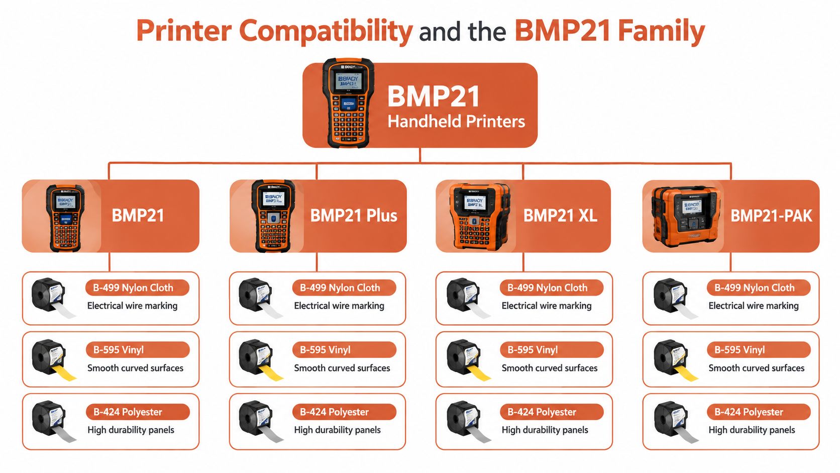
The M21-750-499 is designed for Brady BMP21, BMP21 Plus, BMP21-LAB, ID PAL, and LABPAL handheld printers. The manufacturer datasheet identifies those models as the published compatible printer family.
Match the handheld printer first
A field electrician using a BMP21 or BMP21 Plus typically needs fast wire, cable, and panel identification during installation or service. A panel shop may use the same family for terminal blocks, control-panel components, and retrofit documentation. The BMP21-LAB and LABPAL models serve labeling workflows where the material and printer combination must support laboratory or facility identification.
The important distinction is that printer compatibility and application suitability are separate checks. The label may be ideal for a curved cable jacket, but it still won't work if the printer uses another cartridge footprint. Conversely, a cartridge that physically fits may not provide the material or adhesive behavior required by the project.
Before approving an order, identify the exact printer model on the truck, in the panel shop, or in the maintenance crib. Don't assume that a Brady portable printer from another product line accepts this cartridge. The published compatibility is specific to the BMP21 cartridge family, not every Brady handheld or desktop printer.
For broader asset-identification workflows, Evright Industrial asset tag labeling solutions provide useful context on how printer and material selection changes with the identification task. Teams reviewing the printer, label stock, and field tools together can also use ATEK's tools and testing products as part of a wider equipment procurement review.
Typical Applications in Electrical and Industrial Work
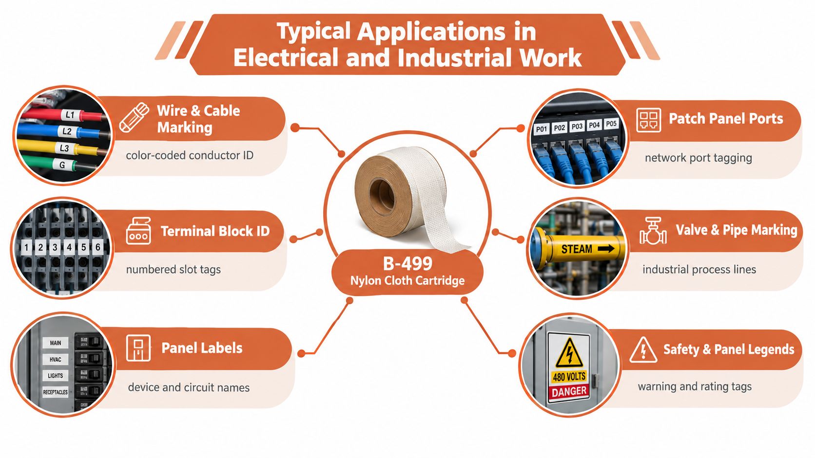
A field technician replacing a cable in a crowded panel needs an identifier that can sit close to the installation without becoming a rigid obstruction. B-499 nylon cloth is pliable, allowing it to conform around curved cable jackets and irregular surfaces. The Newark application description lists wire and cable marking, communications and voice/data identification, panel identification, laboratory identification, and general equipment labeling.
Where the material works well
Wire and cable marking: Wrap or flag a printed identifier around a conductor or cable jacket where a rigid marker would be difficult to position.
Terminal-block identification: Print terminal references during panel assembly, commissioning, and retrofit work.
Control-panel labeling: Mark devices, circuit references, and equipment designations with a compact black-on-white legend.
Voice and data systems: Identify communications cables, patch-panel connections, and related infrastructure.
Laboratory and facility identification: Use the cartridge for handheld, continuous labeling workflows that match the documentation requirement.
General equipment marking: Label suitable equipment surfaces after reviewing the substrate and service conditions.
A service technician may print only the identifiers required for one repair, while a panel builder may produce a repeatable sequence for terminal blocks and device references. Continuous stock supports both workflows and reduces the need to carry several pre-cut marker formats.
Application suitability still requires a site check. Confirm the surface, available clearance, label orientation, and expected handling before approving the cartridge for a specific job. Printer fit is a separate procurement check, so verify the cartridge family against the actual BMP21 printer before ordering substitutes.
For cable routing, identification, and installation planning, these cable management resources help teams assess the label alongside the supports, pathways, and accessories installed around it.
The following video provides additional visual context for handheld industrial labeling workflows.
Environmental Ratings and On-the-Job Performance
B-499 polyamide-coated nylon cloth is described as resistant to abrasion, chemicals, humidity, ultraviolet exposure, and weathering. Distributor data lists an operating temperature range of -40°F to 194°F, approximately -40°C to 90°C, as shown in the Elliott Electric product specification.
That profile makes the cartridge relevant to indoor panels, facility equipment, utility installations, and outdoor enclosures where ordinary paper labels can deteriorate. The material's low profile and pliability are also useful where the identification needs to sit close to a cable or conform around a curved jacket.
Read the rating as a boundary, not a blanket approval
A temperature range doesn't approve every installation. The engineering review should compare the stated product capability with the actual service temperature, exposure duration, substrate, cleaning chemicals, and printing conditions. A label installed on a clean indoor panel face has a different risk profile from one exposed to ultraviolet light, washdown, solvents, or repeated handling.
Substrate matters, too. Product data describes adhesion to surfaces including stainless steel, textured ABS, polypropylene, smooth surfaces, and powder-coated surfaces. That doesn't remove the need for surface preparation. Dust, oil, condensation, release agents, and rough contamination can reduce practical adhesion even when the substrate itself is listed as suitable.
Field observation: The label material and the installation surface have to be treated as one system. A strong adhesive can't compensate for a dirty, wet, or chemically incompatible surface.
For a governed project, retain the current manufacturer documentation and compare it with the equipment environment. If the application involves unusual solvents, sustained exposure beyond the listed conditions, or a high-consequence identification requirement, request technical confirmation instead of relying only on a distributor summary.
Cross-Referencing Equivalent Replacements
When M21-750-499 is out of stock, width and color are the usual starting points. They are not enough for approval. A replacement must match the application, printer interface, and material behavior, not just the finished label's appearance.
Use this checklist to screen alternatives:
Attribute
Required Value
Verification Source
Width
0.75 in, approximately 19.05 mm
Current manufacturer datasheet
Length
16 ft, approximately 4.88 m
Current manufacturer datasheet
Print color
Black on white
Product label and technical data
Material family
B-499 polyamide-coated nylon cloth
Manufacturer material specification
Adhesive behavior
Permanent acrylic adhesive
Technical datasheet
Printer family
BMP21, BMP21 Plus, BMP21-LAB, ID PAL, or LABPAL
Printer and cartridge compatibility data
A practical substitution sequence
Identify the printer. Record the exact handheld model. A same-width cartridge may not fit or feed correctly if the printer is outside the BMP21 family.
Confirm the label envelope. Compare width and continuous length with the BOM, print layout, and clearance around the conductor or component.
Match the material. B-499 nylon cloth is not equivalent to vinyl or polyester merely because each can produce black-on-white labels.
Review adhesive behavior. Confirm the adhesive type and check suitability for the project substrates.
Check the application. Cable jackets, terminal blocks, and enclosure surfaces place different demands on the label.
Verify approvals. Obtain current manufacturer-controlled documentation for any UL, CSA, RoHS, or other project-required compliance claim.
The manufacturer datasheet helps identify the part and intended printer family, but it should not replace a controlled substitution review. If a distributor calls an alternative “equivalent,” request a line-by-line comparison covering material, adhesive, dimensions, printer compatibility, and approvals. Newark listing for M21-750-499 can support part identification, while the approval decision should rest on current controlled documentation.
Procurement checkpoint: Do not approve a substitute from a photograph. Require the datasheet, confirm the printer model, and record why the material suits the installation.
A generic vinyl cartridge may suit a flat, clean surface if the project owner approves it. It does not automatically replace B-499 nylon cloth for cable wrapping, terminal-block work, or a specification that names the material. When stock is short, test the proposed cartridge in the actual printer and verify print placement before releasing it to production or field crews.
Comparing Nylon Cloth to Vinyl and Polyester Labels
B-499 nylon cloth is usually selected for conformability and electrical identification flexibility. Vinyl can be a sensible choice for smooth surfaces, while polyester may be preferred when durability and resistance to heat or chemicals dominate the decision. The correct substitute depends on the installation, not the label's color.
A vinyl label may work well on a flat panel face, enclosure door, or smooth equipment surface. It can be the wrong choice for flagging around a cable if its handling characteristics don't provide the same conformability or adhesion behavior as the specified nylon cloth.
Polyester is often considered for harsher industrial conditions where a more rigid film and stronger resistance profile are needed. That can make it a better engineering choice for demanding panels or solvent-exposed areas, but it may be less forgiving around small-radius cables and irregular surfaces.
The trade-off in plain terms
B-499 nylon cloth: Pliable, low profile, matte, and suited to curved conductors, cable jackets, terminal blocks, and general electrical identification.
Vinyl: Flexible and useful for many smooth-surface applications, but not automatically equivalent for cable wrapping or a governed material specification.
Polyester: More rigid and often selected for high-durability environments, with the trade-off of reduced conformability in some cable-marking situations.
The best comparison starts with the substrate and exposure, then checks the printer. If the job involves a BMP21-family printer and curved cable identification, B-499 remains the direct baseline. If the job involves a flat panel and a different environmental requirement, an approved vinyl or polyester alternative may be more appropriate.
Compliance, Submittals, and Documentation
Product listings identify several compliance signals for M21-750-499, including UL recognition, RoHS compliance, and halogen-free performance under DIN VDE 0472 Part 815. One listing also cites CSA C22.2 No. 0.15-95. Those claims should be verified against current manufacturer-controlled certificates and datasheets before they appear in a formal submittal.
Treat the documentation as part of the purchase:
Confirm the exact part number: Make sure the certificate or datasheet applies to M21-750-499 and its B-499 material.
Check the project requirement: Determine whether the specification needs recognition, compliance, material declarations, or a specific approval.
Retain controlled records: Keep the current manufacturer datasheet, distributor specification, and approved-submittal record with the project file.
Document substitutions: Record the technical comparison and approval when the original cartridge is unavailable.
A distributor bullet point can help locate a product, but it isn't the same as project approval. Engineers and procurement teams should verify the applicable recognition details and confirm whether the completed labeling installation meets the governing equipment, wiring, or facility requirement. For related identification considerations, review the ATEK article on 2026 NEC arc-flash labeling requirements, then apply the requirements that govern the specific installation.
Quick-Reference Summary for Buyers
Keep this reference beside the quote request or BOM review.
Abrasion, chemical, humidity, UV, and weather resistance
Before placing the order, verify the exact printer, label width and length, B-499 material, adhesive behavior, application surface, environmental exposure, and required compliance documents. If the cartridge is short, compare replacements line by line instead of accepting a same-width tape as automatically equivalent.
Frequently Asked Questions About the M21-750-499
Can one cartridge serve multiple jobs?
Yes. Its continuous format lets operators print and cut labels as needed across wire, cable, panel, and terminal-block work.
How do I approve a non-Brady alternative?
Match the printer family, dimensions, material, adhesive, application, and required approvals. Obtain current technical documentation before approval.
How much should I reorder?
Base the quantity on the project label schedule, expected rework, and service stock policy. Don't estimate from cartridge appearance alone.
What if the BMP21 family is being phased out?
Confirm the installed printer fleet and evaluate the replacement printer and cartridge system together. A new printer may require a different cartridge family.
For availability checks, approved alternatives, or a procurement request that combines this cartridge with other electrical materials, contact a qualified industrial distributor before the stockout affects field work.
ATEK Distribution can help source M21-750-499, review the related BOM, and document technically appropriate alternatives when availability is limited. Visit ATEK Distribution to request sourcing support, product availability, or project-specific procurement assistance.
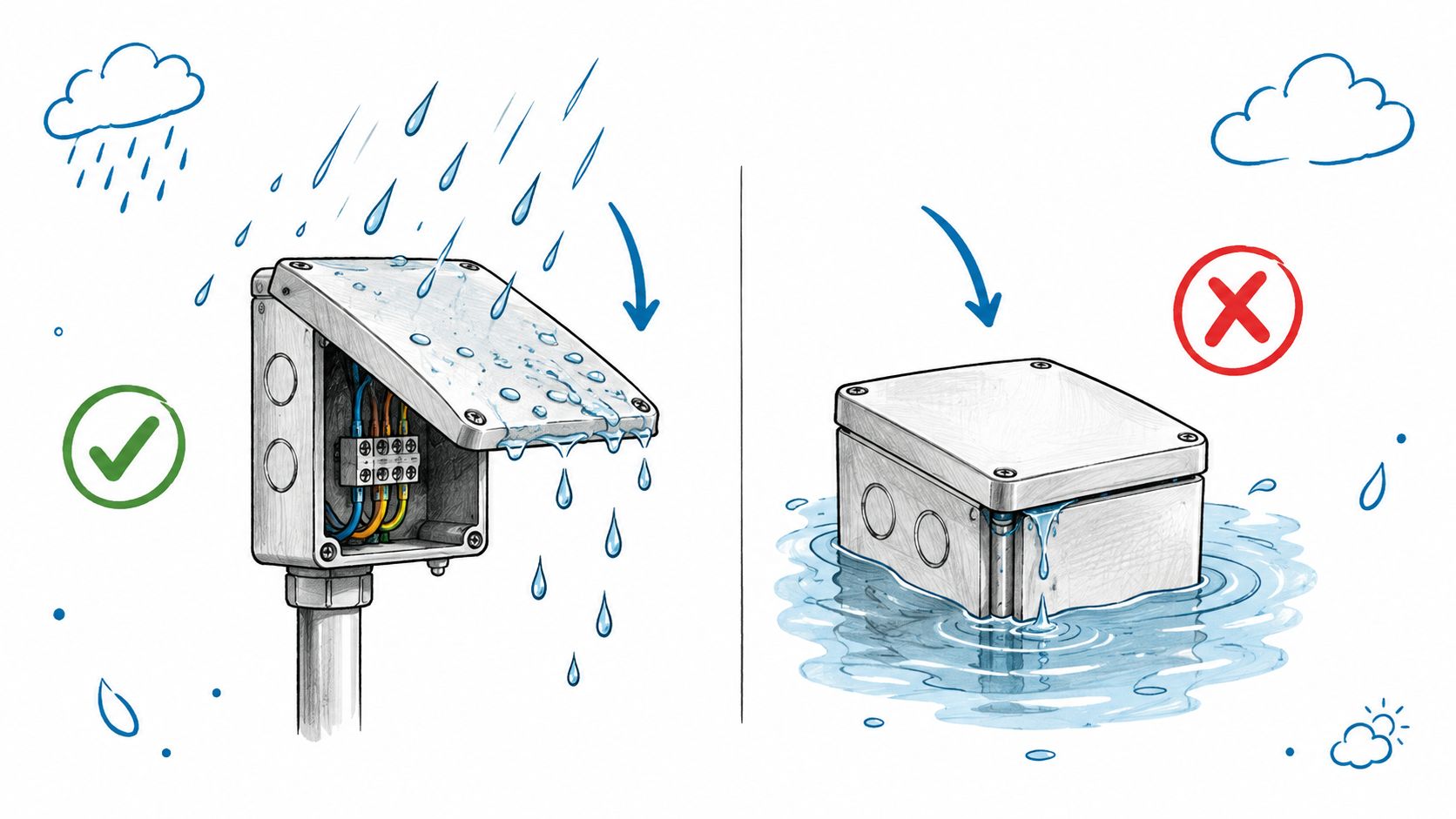
Most bad advice about NEMA 3R junction boxes starts with one lazy phrase, “outdoor waterproof box.” That shortcut causes expensive mistakes. NEMA 3R is built for falling rain, sleet, snow, and external ice formation, but it is not a blanket promise of water-tight or dust-tight performance, and Schneider Electric is explicit that it's typically used for outdoor wiring and junction-box applications, not as a substitute for harsher enclosure types in every environment Schneider Electric FAQ.
The distinction matters because procurement teams, contractors, and facility managers often see “weatherproof” and stop reading. That's how a 3R box ends up in a washdown area, a dusty process space, or a corrosive zone where NEMA 4 or 4X belongs instead. The right specification starts with the actual exposure, not the label on the submittal.
NEMA 3R junction boxes are designed for a narrow but very common job, protecting wiring enclosures from ordinary outdoor precipitation and external icing. They are not the same thing as sealed enclosures. Schneider Electric notes that a typical 3R design does not use a gasketed sealing surface, and it omits the windblown-dust protection associated with NEMA 3Schneider Electric FAQ.
The practical meaning on a jobsite
That difference is easy to miss when a catalog says “weatherproof.” The rating is really an environmental-performance classification, not a synonym for waterproof. Rockwell Automation's documentation also makes the point clear, stating that Type 3R enclosures are not intended to protect against dust, internal condensation, or internal icingRockwell documentation.
If you've ever opened a field-installed enclosure that looked fine on the outside but had moisture on terminals, you already know the problem. The enclosure may have done its job against rain, while the installation failed to manage the moisture path through conduit, openings, or drainage.
Practical rule: use NEMA 3R when the site exposure is mainly rain, sleet, snow, and external ice. Step up when the real hazard is dust, washdown, or corrosion.
Where the rating stops
A NEMA 3R junction box should not be substituted automatically for NEMA 4 or 4X in heavy dust, washdown, or corrosive environments. The box may still be perfectly appropriate for a sheltered exterior junction point, a utility pad, or a general outdoor wiring run. But if the application needs hose-directed water resistance or corrosion resistance beyond ordinary outdoor exposure, 3R is the wrong starting point.
The right habit is to check the complete assembly listing, the installation instructions, and the site conditions together. The rating tells you what the enclosure type was designed to resist. It does not tell you whether the whole installation is suitable.
NEMA 3R Test Standards and Performance Metrics
The strength of NEMA 3R is that it isn't just a marketing term. Rockwell Automation's technical documentation identifies specific design tests for rod-entry, rain, external-icing, and corrosion performance in Type 3R enclosures Rockwell technical documentation.
What the test language tells you
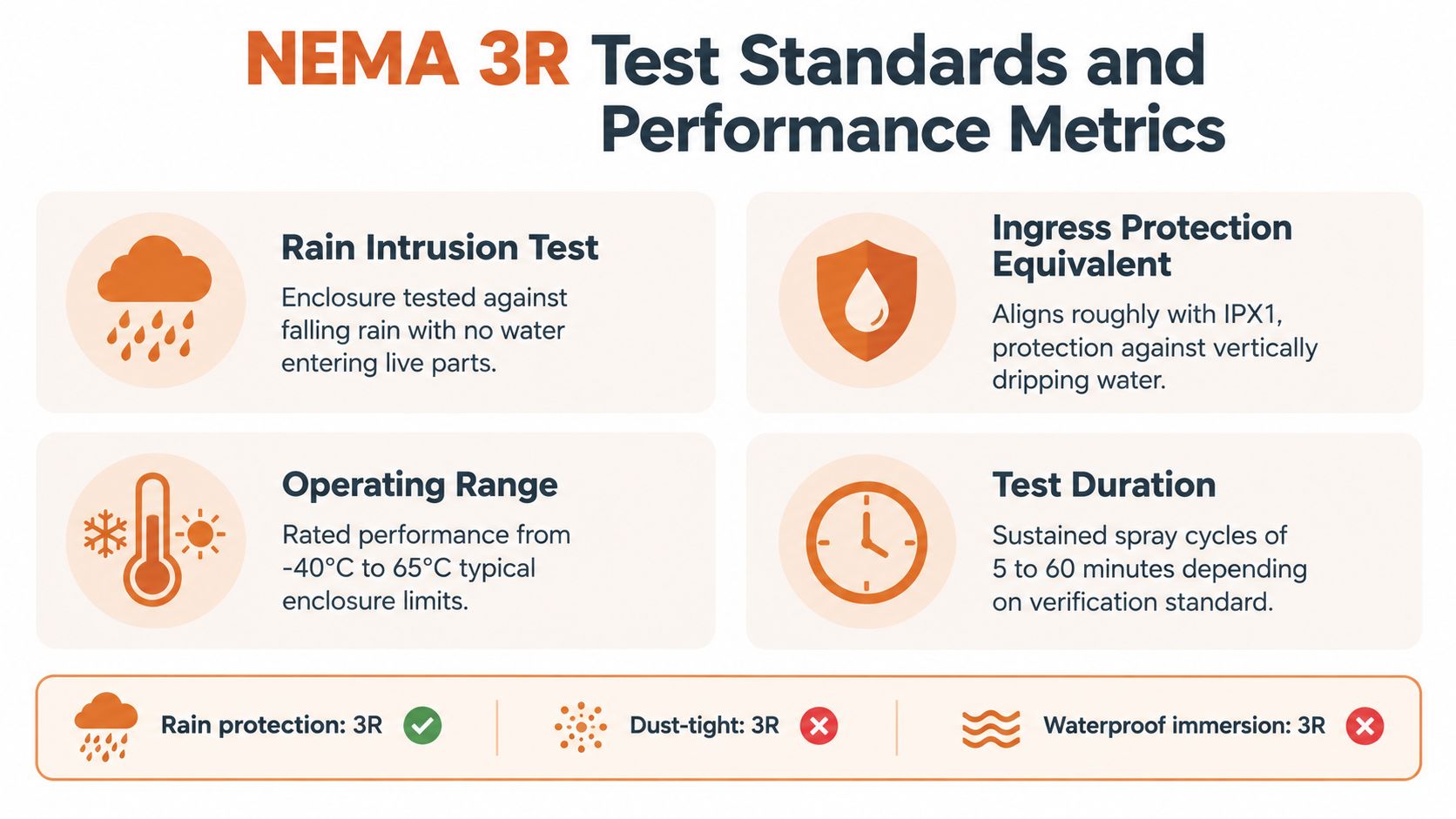
The rain test sprays the enclosure's top and exposed sides at 5 psi for one hour, with water delivered at a rate sufficient to raise the level in a straight-sided pan beneath the enclosure by 18 inchesRockwell technical documentation. The external-icing test starts with one hour of water spray at 2°C, then the enclosure is cooled to about -5°C and held there for three hoursRockwell technical documentation.
Those figures are useful because they show what Type 3R is meant to survive, repeated precipitation and exterior ice formation. They do not describe a sealed system that can ignore every moisture problem. The same documentation says Type 3R enclosures are not intended to protect against dust, internal condensation, or internal icing Rockwell technical documentation.
What buyers should ask for
For procurement and submittals, ask for the test basis and the complete listing, not just the enclosure family name. A box can be sold as “outdoor-rated” while still being wrong for the site conditions. I've seen more mistakes caused by assumptions about the environment than by the enclosure hardware itself.
A good submittal review asks one question first, what is the enclosure defending against, rain, dust, corrosion, temperature cycling, or all four?
Reading the result correctly
The test values matter because they anchor the discussion in measurable performance rather than label language. If the environment includes hose-down, chemical splash, or airborne contamination, the decision has already moved beyond Type 3R. If the exposure is ordinary outdoor precipitation with a practical drainage path, 3R may fit the job well.
Enclosure Materials and Construction Options
Material choice changes how well NEMA 3R junction boxes hold up over time, even when the rating stays the same. The box type describes the environmental class. The material determines how gracefully the enclosure handles corrosion, abuse, and maintenance cycles.
Common material trade-offs
Steel is the familiar default for a lot of outdoor electrical work. It's widely used because it's economical and mechanically strong, especially where the enclosure needs to survive normal industrial handling. Coatings and finishes matter a great deal here, because the base metal alone doesn't tell the whole story.
Aluminum fits general outdoor use where lighter weight and natural corrosion resistance help. It's common when installers need a manageable enclosure that still handles exterior service conditions without pushing into a corrosive environment.
Stainless steel is the better answer near salt air, chemical exposure, or other harsher surroundings. It's the material choice I lean on when the enclosure will face ongoing corrosion pressure, especially if the project needs a longer service life and less touch-up work.
Polycarbonate and other thermoplastic options make sense where the enclosure needs to stay light and non-conductive. They're useful in selected outdoor control applications, but you still have to verify the mechanical demands of the site and the hardware the enclosure will carry.
Material comparison for procurement
Material
Corrosion Resistance
Weight
Cost Range
Best Application
Steel
Moderate with coating
Heavy
Lower to moderate
General outdoor industrial use
Aluminum
Good
Light
Moderate
General outdoor wiring where reduced weight helps
Stainless steel
High
Heavy
Higher
Coastal, chemical, and harsher outdoor environments
Polycarbonate
Good in many non-corrosive uses
Very light
Moderate
Lightweight, non-conductive applications
A smart BOM review looks beyond the enclosure shell. Knockout pattern, finish quality, hardware, and the way the cover sheds water all affect how the box behaves in the field. For projects where sourceability matters, ATEK Distribution can help review enclosure options alongside other outdoor components, but the material decision still has to match the site.
How to Select the Right NEMA 3R Junction Box
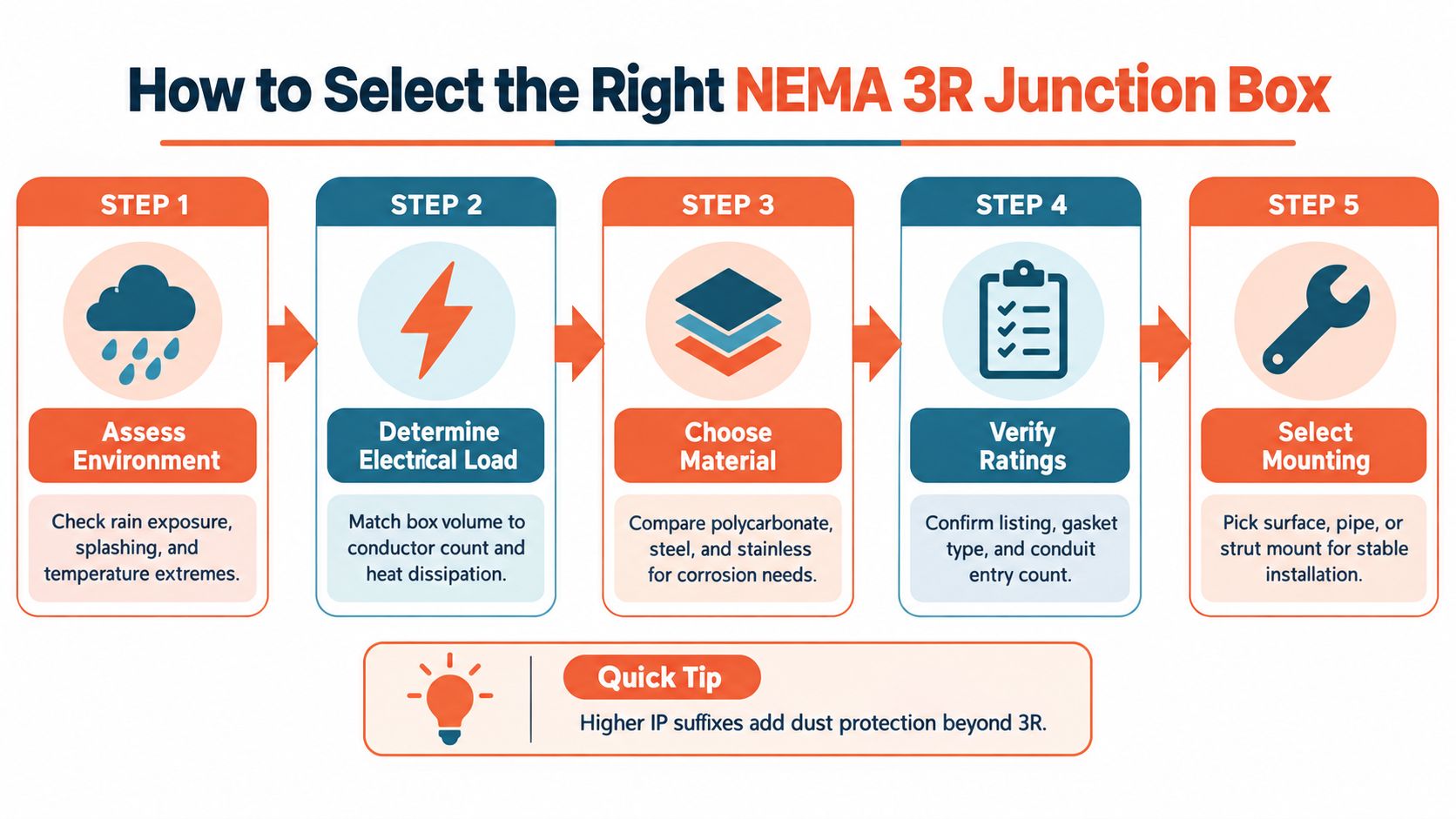
Selection starts with exposure, not catalog pages. If the site sees only ordinary rain, sleet, snow, and external icing, NEMA 3R may be enough. If the site adds washdown, heavy airborne dust, or corrosive atmosphere, the selection should move up before the box is ordered.
A field decision path that works
Assess the environment. Look at precipitation, freezing conditions, splash risk, humidity, and whether the enclosure sits under shelter or in the open.
Match the electrical load to the box volume. The enclosure has to handle conductor fill, bend space, terminations, and any device mounting without crowding.
Check knockout layout. Side and bottom entries usually make more sense than top entries unless the fittings and drainage strategy are deliberate.
Confirm the listing. Verify the complete assembly against the applicable product standard, not just a line in the catalog.
Choose the mounting method. Surface, pole, or strut mounting all affect how the box handles vibration, service access, and water shedding.
The right enclosure often depends on what happens after the box is mounted. Downward-directed conduit entries, listed hubs, and preserved drainage paths matter because they support the rating after installation, not just at the factory.
When 3R is enough, and when it isn't
Use NEMA 3R for ordinary outdoor wiring points, especially where precipitation is the main exposure. Step to NEMA 4 or 4X when the installation needs hose-directed water protection, dust-tightness, or corrosion resistance beyond that level. That's the point where the “weatherproof” label stops being useful and the actual environment takes over.
Mounting is where a good enclosure spec gets saved or ruined. A NEMA 3R junction box can meet its rating on paper and still fail in practice if the hardware, orientation, or conduit entry details fight the design. That's why I treat mounting as part of the enclosure system, not an afterthought.
Three mounting approaches that show up most often
Surface mounting works well when the wall or backing structure is solid and the enclosure is small to mid-sized. Lag screws, anchors, or toggle hardware need to suit the base material, and the box should sit flat enough that covers close cleanly and drainage paths remain open.
Wall mounting on structural supports is the right move when the enclosure needs better alignment, service access, or load transfer into the building frame. It's common in commercial and industrial settings where the enclosure sits near other raceway systems and maintenance crews need clean access.
Pole or pipe mounting is common outdoors for controls, lighting, and utility work. Threaded inserts, bands, or purpose-built brackets need to be selected so the enclosure doesn't twist, rock, or stress the conduit entries over time.
Hardware and entry details that matter
Use listed hubs, strain reliefs, and seal fittings for conduit entries when the installation demands them. Maintain downward-directed entries where practical, because water doesn't care how tidy the submittal looked. Preserve factory drainage paths and don't field-modify a rain hood or drip shield just to make a conduit entry fit.
If the installer has to defeat the enclosure geometry to finish the job, the spec was wrong or the field routing needs to change.
Outdoor controls, utility, lighting, field equipment
Installation Practices and Code Compliance
The rating on the label doesn't override the code or the instructions. Final installation still has to comply with the governing electrical code, including conductor fill, box volume, grounding and bonding, cover accessibility, support, and listed raceway fittings. If the installation doesn't satisfy those basics, the enclosure type won't rescue it.
Where field work usually goes wrong
Knockout sealing is one of the most common misses. If an opening is left unused, it needs to be handled the way the enclosure and code require, not just covered with whatever was in the truck. Incorrect cover orientation causes another set of problems, especially on boxes that depend on a rain hood or drip shield to shed water correctly.
Field modifications can be worse than bad hardware. Drilling through a drainage path, cutting away a protective lip, or forcing an unlisted fitting into place changes how the enclosure behaves under rain exposure. A box that was designed to shed water can start holding it against live parts.
Installation discipline that pays off
Use the manufacturer's instructions and the applicable code together, not one instead of the other. That sounds obvious, but the failure mode is usually a tradeoff made under schedule pressure. Installers make a compromise on the spot, and maintenance teams inherit the problem later.
For a good primer on conductor terminations and related connector habits, the Neasden Hardware push wire guide is a practical reference point, especially when comparing how quick-connect practices affect field assembly quality.
Pair that with the right strain management. ATEK's wiring strain relief resource fits well into submittal review when the conduit run, cable type, or enclosure entry needs extra protection.
Real-World Applications and Failure Modes
NEMA 3R junction boxes perform well in places where the exposure is straightforward. Exterior lighting controls, HVAC junctions, irrigation valve manifolds, and general outdoor wiring on commercial and industrial properties are all sensible uses when the box isn't being sprayed, washed down, or buried in dust. The enclosure's job is to handle weather, not every possible site hazard.
Where 3R works, and where it falls short
The box usually succeeds when the site is semi-sheltered, the conduit entries are sensible, and drainage remains open. That's why 3R shows up so often on building exteriors, utility pads, and equipment yards. It gives crews a practical enclosure without the expense and rigidity of a heavier sealed design.
Failure modes are more predictable than one might think. Internal condensation shows up when temperature cycling moves humid air through raceways, blocked drainage lets water sit where it shouldn't, and corrosion starts at fastener points or scratched finishes. UV exposure can also age seals and plastics faster than crews expect.
Environments that need more than rain protection
Coastal sites and salt-laden air are hard on anything that isn't corrosion-conscious. Tropical sites bring humidity and condensation into the picture, while northern freeze-thaw conditions can trap water in ways that don't show up during commissioning. Solar-heated installations create their own thermal cycling issues, and that can matter just as much as rainfall.
A 3R enclosure can keep rain out of the wrong places and still lose the moisture battle inside the raceway system.
That's why I treat moisture management as a system-level question. The enclosure is one piece. Conduit routing, entry style, drainage, material selection, and maintenance all decide whether the installation holds up.
NEMA 3R vs NEMA 4 and 4X Comparison
Use this comparison when the discussion shifts from “Can we use 3R?” to “Why do we need more protection?” The answer is usually simple once the actual exposure is on the table.
Rating
Rain Protection
Dust Protection
Hose Water
Corrosion Resist
Typical Use
NEMA 3R
Yes, for rain, sleet, snow, and external ice
No
No
No
Ordinary outdoor wiring
NEMA 4
Yes
Better than 3R
Yes
No
Washdown and hose-directed water exposure
NEMA 4X
Yes
Better than 3R
Yes
Yes
Corrosive or washdown environments
The key point is that 3R is not a substitute for 4 or 4X when the installation faces hose-directed water, heavy dust, or corrosive conditions. NEMA 4 changes the water expectation. NEMA 4X adds the corrosion side of the problem. That's a real step up, not a marketing upsell.
If the box will live near washdown lines, wastewater equipment, food-processing zones, or salt exposure, stop trying to make 3R fit. Specify the rating the environment actually demands.
Inspection and Maintenance Checklist
A NEMA 3R junction box should be inspected like any other outdoor electrical enclosure, because time and weather eventually test every shortcut. Quarterly visual checks catch the obvious damage, and that's usually where the first warning signs show up.
Field checklist
Cover condition: Check for cracks, warping, bent edges, or damage that keeps the cover from seating properly.
Drainage path: Make sure weep points and drain paths are open, not blocked by dirt, sealant, or debris.
Fasteners and hardware: Look for loosened screws, rust, or galvanic corrosion at mounting points.
Knockout integrity: Verify that unused openings are sealed the way the enclosure listing and site practice require.
Internal moisture: Open the box during scheduled service and look for condensation, staining, or corrosion.
Terminations and grounding: Confirm the terminals are tight, clean, and free of heat damage or oxidation.
Labeling and identification: Make sure the box still matches the circuit, area, and maintenance records.
Annual checks should cover grounding continuity and the general condition of terminations. In harsher environments, a more detailed review makes sense on a shorter cycle, especially where service downtime is expensive.
The point isn't to baby the enclosure. It's to catch the slow failures before they become a weather-related outage or a nuisance alarm.
Procurement Guidance and ATEK Support
Buying NEMA 3R junction boxes is easy when supply is normal and the project is simple. It gets harder when the spec needs documentation, the lead time slips, or the material that was approved in the design isn't available when the job hits procurement. That's where disciplined sourcing matters as much as the enclosure spec itself.
ATEK Distribution works as an electrical products distributor and procurement partner for contractors, engineers, facility teams, utilities, OEMs, and government buyers. In this space, that usually means BOM review, product sourcing, approved alternatives, compliance documentation, and manufacturer coordination when the original item is constrained or obsolete. For mission-critical work, those services keep jobs moving without forcing a bad substitution.
The most useful procurement questions are practical. Is the enclosure truly listed for the exposure? Is the material suitable for the environment? If the specified box is unavailable, what approved alternative preserves the rating and the installation intent?
For buyers managing multiple jobs, it helps to have one partner who can source junction boxes alongside fittings, protective devices, and related enclosure hardware. ATEK can support that workflow while keeping the enclosure choice tied to the site conditions instead of the catalog headline.
If you're sourcing NEMA 3R junction boxes for a project and need help matching the enclosure to the exposure, ATEK Distribution can review your BOM, suggest approved alternatives, and help with compliance-minded sourcing. Visit ATEK Distribution to request project support and keep the procurement moving without guessing at the enclosure rating.
A NEMA 3R pull box isn't a watertight outdoor box, and treating it like one is a reliable way to create water-ingress, corrosion, and inspection problems. The rating is designed for ordinary rain, sleet, snow, and external ice formation. It doesn't make an enclosure suitable for hose-down cleaning, windblown dust, corrosive atmospheres, or flood exposure.
The other common mistake happens before the box reaches the jobsite. Catalog shopping often starts with conduit diameter and available stock sizes, while the actual box dimensions must account for conductor size, pull geometry, raceway arrangement, fittings, cover access, and environmental construction. A box can carry the right NEMA marking and still be the wrong part for the installation.
The “weatherproof” label deserves more scrutiny. NEMA Type 3R is an enclosure classification under ANSI/NEMA 250, not a universal promise that water can't enter. The current standards summary identifies ANSI/NEMA 250-2020, which revised and superseded the 2018 edition, as the applicable edition for electrical equipment rated at no more than 1,000 volts. The standard treats Type 3R as an enclosure category, so a pull box, junction box, wireway, or similar enclosure can qualify when its construction and testing meet the applicable requirements. ANSI's summary of ANSI/NEMA 250-2020 provides the broader standards context.
A NEMA 3R pull box is intended for indoor or outdoor use in nonhazardous locations. It protects personnel from incidental access to hazardous parts, shields enclosed equipment from falling dirt, and limits the harmful effects of falling rain, sleet, and snow. The classification also addresses damage caused by external ice formation, which matters for exposed infrastructure in northern climates.
What Type 3R does not cover
Type 3R is narrower than NEMA Type 3. It doesn't provide the same protection against windblown dust, and it shouldn't be treated as dust-tight, watertight, or suitable for direct hose spray. A drainage-based enclosure manages ordinary outdoor exposure. It isn't designed to stop every form of water from reaching the interior.
Use the site conditions to make the selection:
Ordinary exterior exposure: A 3R box may suit a service entrance, outdoor raceway transition, rooftop location, or sheltered industrial installation.
Windblown dust: Consider an enclosure classification intended for that particulate exposure instead of assuming Type 3R is sufficient.
Washdown or directed water: A higher rating is generally needed where cleaning hoses or spray can strike the enclosure.
Flood-prone or submerged locations: Type 3R is not a submersion rating.
Corrosive atmospheres: Evaluate the enclosure material, finish, fittings, and a more protective rating as a complete system.
Practical rule: Select NEMA 3R because the exposure is ordinary rain and snow, not because the product description uses the word “weatherproof.”
The difference between a drain-managed enclosure and a sealed heavy-duty enclosure is useful when reviewing alternatives. For additional background on enclosure construction and application trade-offs, see why choose these heavy duty boxes. For an outdoor selection workflow, the guide to choosing electrical enclosures for outdoor use is also relevant.
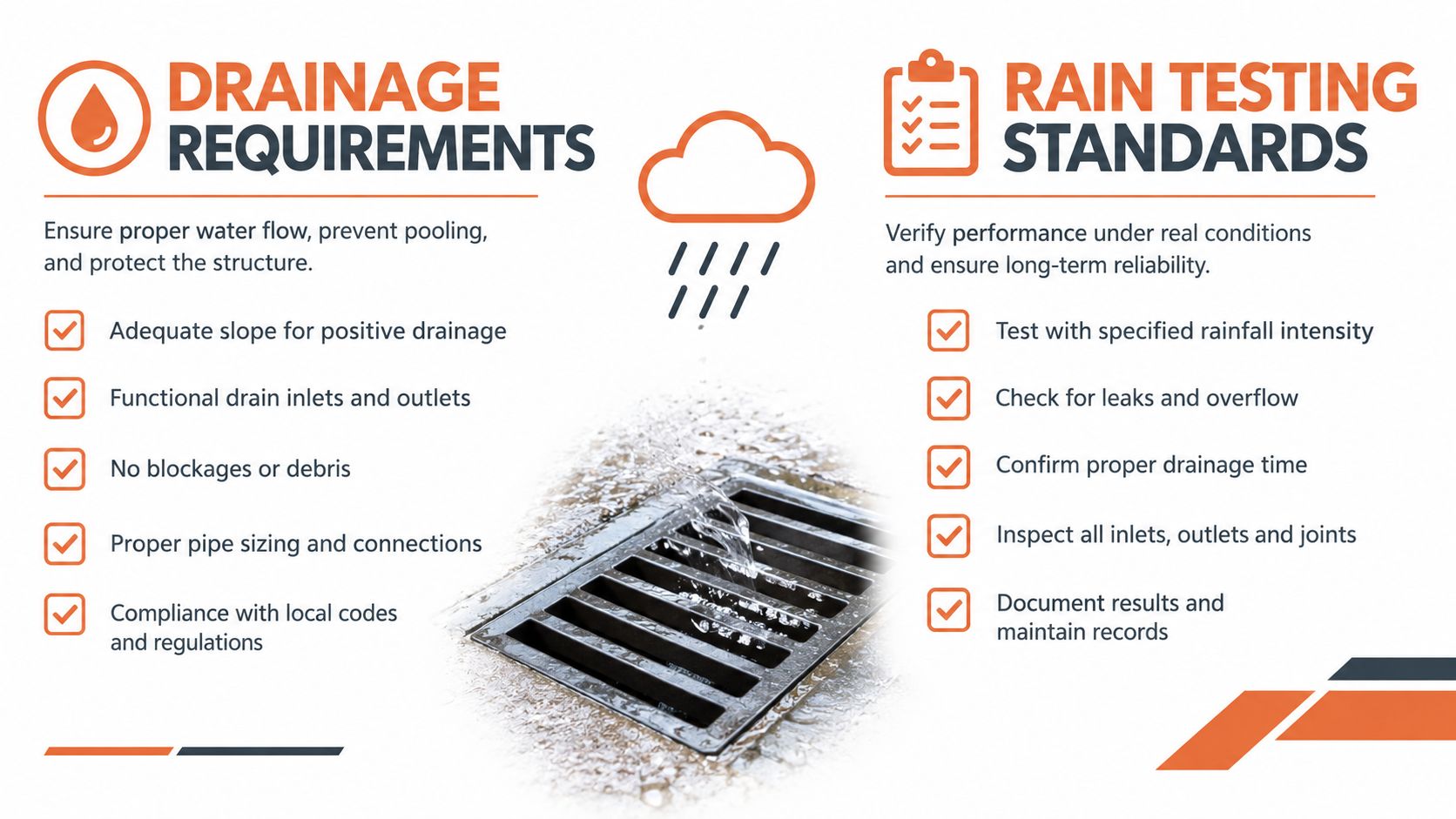
Drainage Requirements and Rain Testing Standards
A Type 3R enclosure is expected to manage water, not necessarily exclude every drop. That design choice explains why drainage openings, cover geometry, seams, knockouts, and installation orientation all matter. A generic metal box with a rain hood isn't automatically a compliant NEMA 3R pull box.
Under the NEMA 250 provisions summarized in the available standard text, Type 3R drainage openings must be at least 3.2 millimeters, or 1/8 inch, and no more than 6.4 millimeters, or 1/4 inch, in diameter. Openings below the minimum may not provide the required drainage capacity. Openings above the maximum can affect the enclosure's intended environmental protection and permit unacceptable foreign-material entry. The available NEMA enclosure text describes the drainage provisions and associated construction requirements.
Testing matters more than appearance
Rockwell Automation's technical bulletin describes a Type 3R rain test in which the enclosure's entire top and exposed sides are sprayed with water at 5 psi for one hour. The flow is sufficient to raise water 18 inches in a straight-sided pan beneath the enclosure. The acceptance criterion is that water must not reach live parts, insulation, or mechanisms. Rockwell Automation's Type 3R technical bulletin also identifies rod-entry, external-icing, corrosion, drainage, and drip-shield considerations.
That test doesn't certify every field-modified arrangement. The listed assembly includes its cover, seams, openings, and construction details. A contractor who drills an unapproved penetration, installs an unsuitable hub, or leaves a cover misaligned may change the water path that the tested design controlled.
Schneider Electric notes that Type 3R enclosures commonly use side and bottom knockouts and aren't gasketed sealing systems. Beating rain or directed water can enter under certain conditions. Procurement should therefore verify the manufacturer's NEMA 250 Type 3R listing or certification, not rely on galvanized steel, a gasket added after purchase, or a “rainproof” phrase in a catalog title.
Calculating Pull Box Dimensions Under NEC 314.28
The NEMA rating answers an environmental question. NEC 314.28 answers the geometry question. For a NEMA 3R pull box containing conductors rated 4 AWG or larger, the box must be sized from the raceway and conductor arrangement, not selected solely by conduit diameter or catalog availability. The NEC 314.28 discussion summarizes the dimensional approach for straight pulls, angle pulls, U-pulls, splices, and multiple raceway rows.
Start with the pull configuration
For a straight pull, measure from the raceway entry to the opposite wall. The distance must be at least eight times the trade size of the largest raceway.
For an angle pull, use six times the trade size of the largest raceway, then add the sum of the trade sizes of the other raceways entering the same wall and row. A U-pull uses the same six-times-plus-sum method. Splices require the applicable pull calculation rather than an assumption that a standard pull-box dimension is sufficient.
The table below applies the required multipliers to a largest raceway with a 4-inch trade size. The numerical methods are based on the cited NEC 314.28 discussion.
Pull Type
Calculation Method
Example, 4-inch largest raceway
Straight pull
8 × largest raceway trade size
8 × 4 inches = 32 inches
Angle pull
6 × largest raceway trade size + sum of remaining raceways on the same wall and row
6 × 4 inches + remaining raceway trade sizes
U-pull
6 × largest raceway trade size + sum of remaining raceways on the same wall and row
6 × 4 inches + remaining raceway trade sizes
Build the schedule before buying
A dimensional pull-box schedule should identify the largest raceway, every other raceway on each applicable wall and row, the pull type, conductor size, and the calculated distance. Multiple raceway rows are evaluated individually, with the row producing the largest result controlling. Raceways carrying the same conductor must generally be separated by at least six times the largest raceway trade size, measured edge to edge.
The calculation is only the beginning. Check conductor bending space, hub depth, bonding provisions, cover removal, drain placement, and the actual fitting geometry. A box that meets a length calculation but blocks the cover with a hub or leaves no practical room for the conductors isn't a successful selection.
When raceway material and box procurement are being coordinated, keep the approved conduit system visible in the BOM. For example, an ATEK PVC conduit product category can support the material review, but the final box still has to match the engineered raceway layout and applicable code requirements.
Material Selection and Corrosion Resistance
NEMA 3R describes environmental protection. It doesn't specify one universal enclosure material. A galvanized steel pull box, painted steel box, aluminum enclosure, and fiberglass composite enclosure may all serve different projects, provided the selected product meets the required construction and certification requirements.
Galvanized steel is often practical for ordinary commercial and industrial exposure. It provides a sturdy enclosure structure and can be economical for larger pull boxes. Its weakness appears when the zinc coating is damaged, cut, abraded, or exposed to persistent salt or chemical contamination. Field-drilled holes and poorly protected edges deserve the same attention as the main panel surfaces.
Painted steel can work where the finish is appropriate for the environment and remains intact. It becomes a poor long-term choice when the coating system isn't compatible with humidity, industrial pollutants, or repeated handling. A small scratch around a mounting point can become the starting point for corrosion if maintenance teams don't address it.
Match the material to the exposure
Aluminum can reduce weight and offers useful corrosion resistance in many outdoor applications, but compatibility with nearby metals, fittings, and the atmosphere still needs review. Fiberglass composites can be useful where low weight, electrical isolation, or resistance to selected corrosive conditions is important. Neither material eliminates the need to verify the product's Type 3R construction and the suitability of its fittings.
Coastal salt air deserves specific scrutiny. Siemens identifies humid salt air as particularly corrosive to electrical products, so a standard finish that performs acceptably inland may require a different material or protection strategy near the coast. High-humidity tropical sites, industrial pollution, chemical vapors, and rooftop temperature cycling can produce similar lifecycle concerns.
The lowest purchase price isn't the same as the lowest installed cost when corrosion forces a replacement, outage, or emergency field modification.
Review the complete assembly rather than the shell alone:
Base material: Confirm whether galvanized steel, aluminum, fiberglass, or another construction suits the site.
Finish and cut edges: Check how the manufacturer treats exposed edges, mounting points, and factory knockouts.
Hardware: Door fasteners, hinges, bonding points, and hubs can become the first corroded components.
Drainage: Ensure drain paths remain functional after mounting and conduit installation.
Maintenance access: Select a cover arrangement that allows inspection without damaging the enclosure.
Conduit Entries and Field Modification Risks
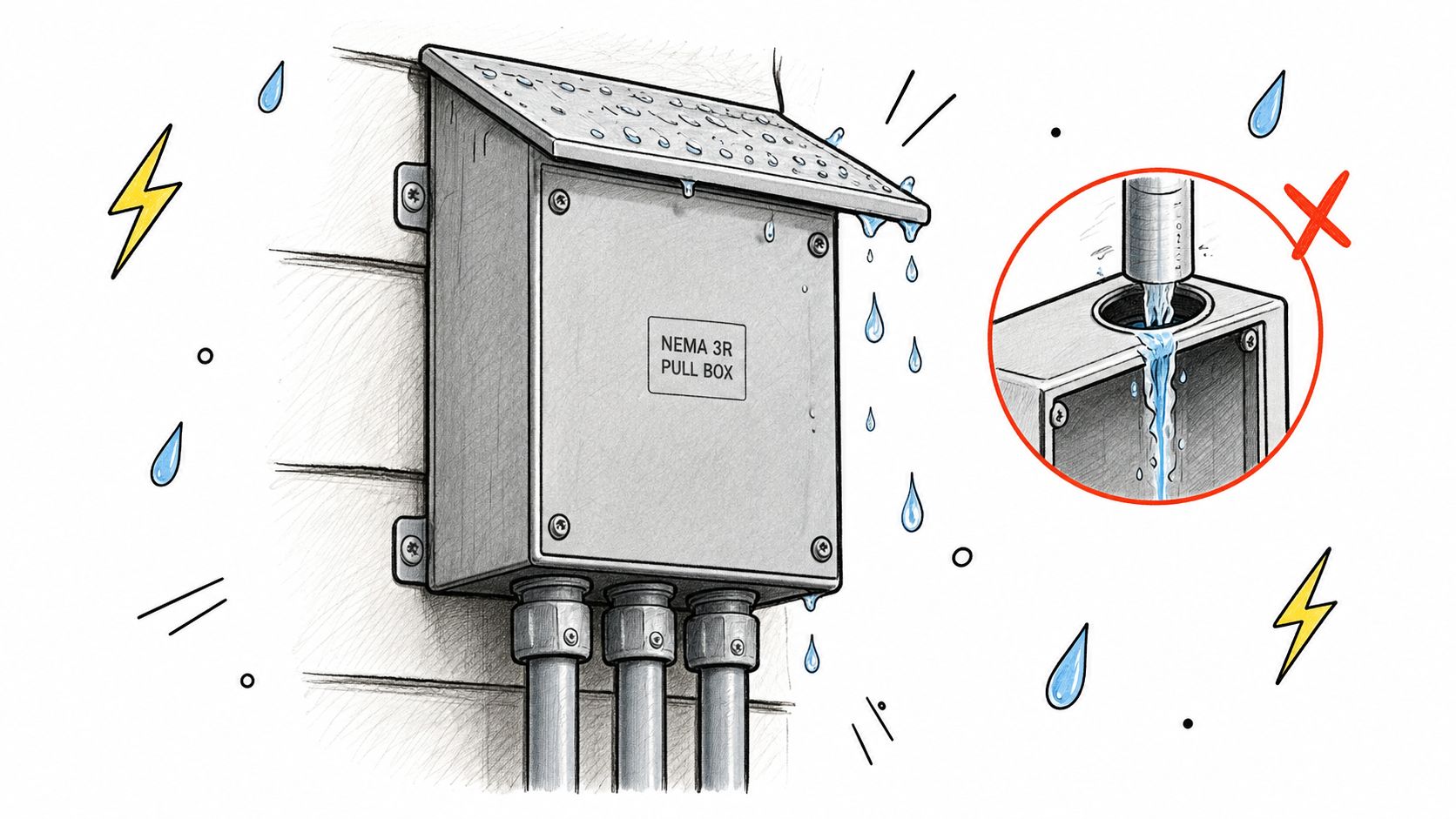
A correctly sized box can still admit water if the conduit entries create a direct path into the enclosure. Entry location is part of environmental performance. Top entries are especially vulnerable because water can run along the conduit or fitting and discharge directly inside the box. Bottom or protected side entries generally reduce that risk when the product instructions and installation conditions support them.
Siemens notes that Type 3R enclosure openings and conduit fittings must meet prescribed provisions. The practical lesson is straightforward: the hub, connector, knockout, cover, and enclosure must function together. A field-installed fitting isn't automatically acceptable just because it threads into the opening.
Modifications can change the listing
Adding an aftermarket gasket is one of the most persistent misconceptions. A gasket may reduce a visible gap, but it doesn't automatically convert a Type 3R enclosure into a higher environmental rating. The enclosure's entire construction and test performance determine its classification.
The same caution applies to drilling unlisted holes, relocating drainage openings, enlarging knockouts, replacing covers, and using fittings that weren't evaluated for the assembly. These changes can alter water flow, foreign-material entry, bonding, clearances, and the ability of the cover or drip shield to perform as tested.
Before field work begins, confirm:
The manufacturer's permitted entry locations and knockout sizes.
The hub or fitting type approved for the enclosure.
Whether unused openings require listed closures.
How the installation preserves drainage and cover alignment.
Whether the completed assembly remains within the manufacturer's certification.
Top entry may be unavoidable in a specific layout, but it should trigger a deliberate review of the fitting and water path. A short raceway change or protected entry can be cheaper than replacing a corroded pull box after the first season.
Managing Internal Condensation and Moisture
Rain is only one moisture source inside a NEMA 3R pull box. Warm, humid air can enter through conduit pathways, fittings, and other openings, then condense as the enclosure cools. The cover, conductors, terminals, and splice hardware can all become condensation surfaces without any visible water leak.
The risk increases in coastal and tropical locations, on rooftops, near refrigerated equipment, and wherever temperatures cycle sharply. A Type 3R rating covers defined protection against falling rain and external ice formation. It does not keep the interior dry or prevent humidity exchange from producing condensation.
Control the moisture path, not just the enclosure opening
Sealing every opening may trap humid air inside. Cooling then leaves moisture with no practical path out. Uncontrolled ventilation creates the opposite problem by admitting more humid air. Choose the response based on enclosure volume, internal heat, ambient humidity, and the sensitivity of the equipment inside.
A field moisture-control plan should address these points:
Open drainage: Keep factory drain provisions clear after mounting and conduit work.
Protected entries: Do not create direct water paths through exposed top entries.
Listed breather or drain devices: Use these only when they suit the enclosure and installation.
Anti-condensation heating: For sensitive equipment in severe temperature cycles, evaluate listed heaters with thermostatic controls.
Inspection: Check for terminal corrosion, discolored insulation, moisture marks, and blocked drains during maintenance.
Condensation protection extends to the contents of the box. Splices and underground transitions require products selected for their own exposure, not merely a weather-rated outer enclosure. An underground wire splice kit category may suit buried or moisture-exposed conductor transitions, provided the kit rating and installation method match the project.
A drain blocked by sealant, debris, paint, or an uneven mounting surface can defeat the intended moisture strategy. Treat the drain path as a working part of the enclosure, and verify it after installation and during service inspections.
Placement Rules and Raceway Pathway Limits
A NEMA 3R pull box can meet its enclosure rating and still be the wrong choice for the raceway layout. Project specifications may govern its location, accessibility, conduit length, bend accumulation, entry arrangement, and cover clearance. Those requirements often exceed the basic enclosure criteria, especially in institutional, communications, and mission-critical installations.
The University of Houston communications-pathway specification illustrates the point. It calls for NEMA 3R pull boxes in damp or wet locations, including plumbing chases and outdoor areas, while permitting NEMA 1 boxes indoors. It limits conduit runs between pull boxes to 100 feet, requires a pull box when a run includes two 90-degree sweeps or 180 degrees of total bends, and prohibits using a pull box to change the direction of a conduit run. The University of Houston pathway specification records these project-specific requirements.
Let the raceway geometry determine placement
Place the box where it supports the pull, not where the catalog dimensions happen to fit. An unplanned direction change can produce poor pulling geometry and conflict with the specification. The raceway should establish the route, while the box provides an accessible pull point.
Field conditions create additional risks. A box behind equipment, beside a structural obstruction, or in a position that prevents cover removal may pass a submittal review but fail during pulling or maintenance. Avoid locations that encourage cutting new entries on site, particularly on exposed faces. An improper conduit entry, damaged gasket, or unsealed modification can compromise the enclosure rating.
Before release, verify the specified enclosure type for the actual location, conduit distance between pull points, total bends, sweep geometry, access for inspection and future service, and box dimensions calculated under NEC 314.28 where applicable. Confirm the entry pattern, cover clearance, fittings, labeling, submittals, approved manufacturers, and any owner requirements.
The University of Houston example is not a universal rule for every project. Review the contract documents, engineered drawings, applicable NEC requirements, and manufacturer instructions together. That review prevents catalog availability from dictating a layout that cannot be installed or serviced properly.
Streamlining Procurement and BOM Management
Treat the pull box as a coordinated electrical assembly, not a commodity line item. A shortage of one size can force changes to conduit routing, cover access, fittings, conductor pulling, inspection, and the schedule. A substitute with the same NEMA designation may still fail if its dimensions, entry provisions, or construction do not suit the installation.
Make the BOM carry the installation decision
The purchase record should include the calculated box dimensions under NEC 314.28, the actual pull geometry, approved conduit-entry arrangement, material, cover configuration, drain provisions, fittings, and bonding requirements. This prevents catalog availability from overriding the design.
Field modifications deserve specific review. Drilled entries, mismatched hubs, damaged gaskets, and unsealed fasteners can compromise the Type 3R rating. Condensation provisions also need to remain compatible with the enclosure and its location. A replacement that fits the conduit may still create a moisture or corrosion problem.
Before issuing a purchase order, confirm:
the proposed manufacturer supplies Type 3R documentation;
hubs, connectors, closures, covers, and bonding parts are compatible;
the selected material and finish suit the exposure;
the box accommodates the calculated pull and conductor arrangement;
submittals and compliance documents are available;
the engineer, owner, or authority having jurisdiction accepts the alternate.
Record these decisions against the BOM rather than leaving them in email correspondence. That gives estimators, procurement staff, installers, and inspectors the same reference when availability changes.
Estimating tools can connect the enclosure, raceway, fittings, labor, and substitution effects in one takeoff. Teams revising electrical quantities can evaluate Exayard electrical estimating software alongside their existing estimating and specification workflow.
ATEK Distribution supports sourcing, hard-to-find component identification, alternate evaluation, material consolidation, specification review, submittals, and compliance documentation. Its SDVOSB and supplier-diversity credentials may also support documented government or institutional procurement objectives.
A distributor should reconcile the approved specification with availability, compatible accessories, documentation, and delivery requirements. The engineer retains responsibility for product selection.
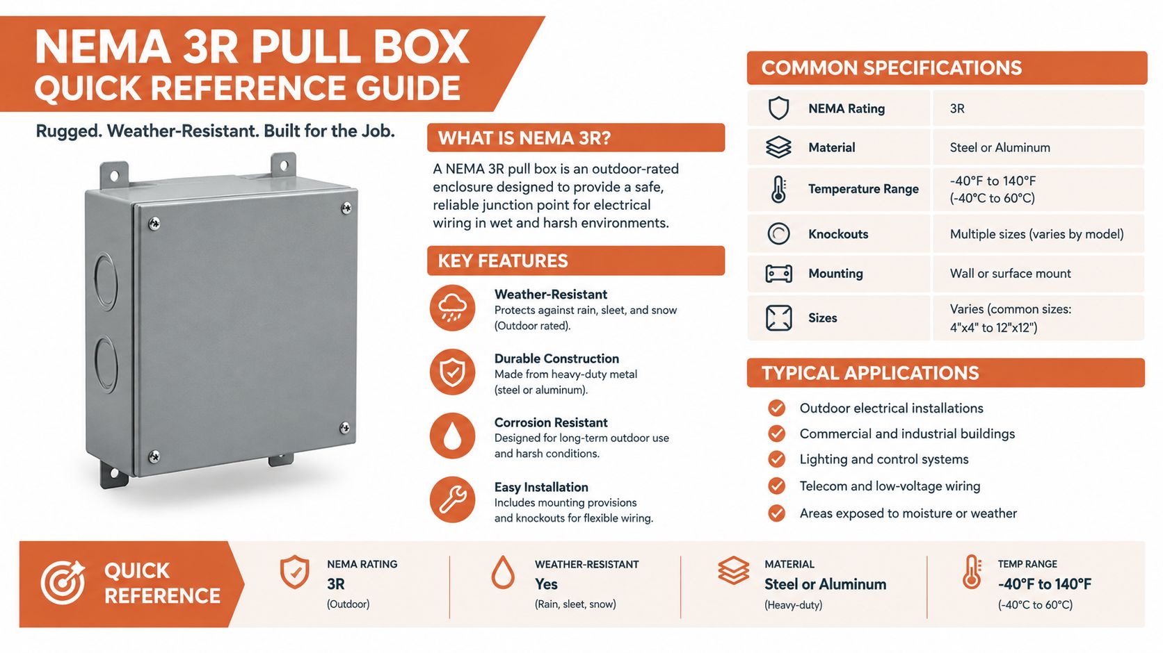
NEMA 3R Pull Box Quick Reference Guide
Use this guide as a final office or field check. It doesn't replace the applicable code, project specification, manufacturer instructions, or engineering review, but it can identify the questions that deserve attention before procurement.
Environmental selection
Check
Practical interpretation
Type 3R purpose
Indoor or outdoor, nonhazardous locations with falling rain, sleet, snow, and external ice exposure
Falling dirt
Protection is included within the Type 3R classification
Windblown dust
Type 3R doesn't provide the same protection as Type 3
Hose-directed water
Don't use Type 3R as a washdown solution
Flood or submersion
Select an enclosure evaluated for that exposure
Corrosive atmosphere
Review material, finish, fittings, and whether a different rating is needed
Construction and testing
Drain openings: Keep openings within the 1/8-inch minimum and 1/4-inch maximum boundary described in the NEMA 250 provisions summarized by the available standard text.
Rain testing: The Rockwell Automation bulletin describes exposure at 5 psi for one hour, with water directed over the top and exposed sides.
Assembly integrity: Treat the enclosure, cover, openings, hubs, fittings, and drainage as one tested construction.
Field modifications: Don't assume an added gasket, drilled hole, or replacement cover preserves the original rating.
Conduit entries: Bottom or protected side entries can reduce direct water paths compared with exposed top entries.
Sizing and installation
For conductors 4 AWG or larger, apply NEC 314.28. A straight pull uses eight times the largest raceway trade size. An angle pull or U-pull uses six times the largest raceway trade size plus the sum of the other raceways on the same wall and row. Evaluate multiple rows individually, and check separation, bending space, cover removal, hub depth, bonding, and drain clearance.
Procurement checkpoint: Don't release the box until the dimensional schedule, environmental selection, entry arrangement, accessories, and approved product documentation agree.
Material selection should reflect the site. Galvanized or painted steel may suit ordinary exposure when the finish is appropriate. Aluminum or fiberglass may be more suitable for selected weight or corrosion conditions, but the complete product still requires review. In humid salt air, industrial pollution, or persistent high humidity, lifecycle maintenance deserves more attention than the initial catalog price.
Finally, check the pathway rules. Owner specifications may govern pull-point spacing, bend accumulation, accessibility, and whether a pull box can be used for a change in conduit direction. Those requirements can determine the right location and dimensions before anyone selects a catalog number.
For a project requiring a NEMA 3R pull box, ATEK Distribution can help review the BOM, source standard or hard-to-find enclosure sizes, evaluate approved alternatives, and assemble the submittal and compliance documentation. Visit ATEK Distribution to request sourcing support for your electrical enclosure and raceway requirements.
A crimped splice can look finished when the panel door closes and still become the source of a difficult callback. The usual causes aren't mysterious: the installer used the wrong tool, stopped before the controlled cycle released, stripped the conductor too far, or selected a connector for a different wire combination. Permanent connections demand more discipline than a quick squeeze with whatever tool is already on the belt.
Why Buchanan Crimp Connectors Matter in Industrial Electrical Work
Buchanan crimp connectors are permanent, pressure-type splice devices. Unlike a removable terminal, the connector is compressed around the conductors with a dedicated tool, creating a mechanical and electrical joint intended to stay in place. That makes the connector useful where vibration, limited access, or the need for a compact splice makes other methods less practical.
Buchanan's tooling history reaches back to the formalization of high-reliability crimping. The company introduced a 4-indent crimp tool with a ratchet in 1960, while the first crimp tool standard, MS3191-1, was published in 1963. MIL-T-22520 followed in 1969, later becoming MIL-C-22520 and then MIL-DTL-22520, as documented in this high-reliability electrical tooling guide. Buchanan was also listed in the first Qualified Products Listing for QPL-22520 in 1969, placing the brand within the early standardized crimp-tooling ecosystem.
What the method changes in the field
A wire nut is convenient and readily removable. A soldered splice can provide a sound electrical joint when the process, support, insulation, and applicable requirements are all controlled. A Buchanan crimp splice takes a different route. It relies on a correctly sized sleeve, the right conductor combination, and repeatable compression.
That repeatability is why tooling matters more than the connector's unit price. A government technical report estimated that about 70 billion crimp-type wire terminations were used annually in the United States, and its collected field data recorded no failures in the observed set. The report concluded that field failures of crimp connections were rare, supporting the method's broad use in demanding electrical and electronic applications. Read the technical report on crimp termination reliability for the historical context.
This guide focuses on the 2006S family and 2011S class, their conductor ranges, the Buchanan C24 and P24 tools, installation checks, and the situations where generic pliers are a poor substitute. That information helps contractors, panel builders, engineers, and buyers make a defensible selection before material reaches the jobsite.
Crimp Connectors vs Wire Nuts vs Soldered Splices
The right termination method depends on more than speed. The crew has to consider vibration, access for future work, conductor compatibility, enclosure space, and the documentation required for approval.
Termination type
Vibration resistance
Rework capability
Installation speed
Best industrial use case
Buchanan crimp connector
High when correctly matched and compressed with the specified tool
Low after crimping
Fast after the process is established
Permanent splices in equipment, panels, utility, and industrial wiring
Wire nut
Suitable only where the connector and application permit it
High
Fast
Accessible junctions where removable splicing is appropriate
Soldered splice
Depends heavily on workmanship, mechanical support, and environment
Low to moderate
Slower
Specialized electronics or assemblies designed around soldering
Wire nuts remain useful where technicians need to open a junction repeatedly, provided the connector is listed and suitable for the conductors and enclosure. They can be a poor choice in locations where vibration, movement, or limited inspection access makes loosening and conductor disturbance a concern. Solder can also be appropriate, but solder alone shouldn't be treated as a mechanical strain-relief system for ordinary building or industrial wiring.
For a broader comparison of removable twist-on methods and push-in products, see this comparison of push-in connectors and wire nuts. The point isn't that one method wins everywhere. The point is to match the termination to the circuit's service conditions and the approved installation method.
Field rule: If the splice is intended to remain in place and the conductors will see vibration or movement, select the connector and tool as one installation system.
A Buchanan crimp splice makes the most sense when the contractor wants a compact, permanent connection and can control the conductor range, strip length, tool selection, and inspection process. It isn't the answer for every repair. It is a strong option when rework is unlikely and consistent compression is more valuable than easy removal.
Buchanan Crimp Splice Families and Specifications
The two families most relevant to common Buchanan splice-cap work are the 2006S family and the 2011S class. They aren't interchangeable just because both are copper crimp connectors. The wire range and approved combinations determine which one belongs on the bill of materials.
Connector family
Conductor range
Voltage rating
Key compliance note
Buchanan 2006S
18 to 10 AWG solid copper
600 VAC
Listings note UL 486C and CSA C22.2 #188
Buchanan 2011S / 2011SB
14 to 4 AWG
600 V AC
Intended for permanent pressure-type connections, with published wire-combination limits
The 2006S family is specified for 18 to 10 AWG solid copper conductors, with a 600 VAC rating and a maximum operating temperature of 221 °F. Its approximate physical envelope is 0.211 inches in diameter by 0.425 inches in length. The product listing identifies 2006S specifications and compliance details, including UL 486C and CSA C22.2 #188.
That compact size can help in a crowded enclosure, but the small body doesn't eliminate the need to confirm conductor count and combination. Use the listed combination, not just the nominal gauge, when ordering.
Where the larger family fits
The 2011S and 2011SB class extends the range to 14 through 4 AWG. Listings describe the products as fast, permanent, pressure-type connections and identify compatibility with the Buchanan C24 crimp tool. The solid copper sleeve is described as requiring less crimping pressure and offering improved corrosion resistance in harsh environments, a useful characteristic for vibration-prone OEM, utility, and facility wiring. Review the 2011SB product details before approving a substitute.
The 2011S listing shows approved combinations including two 10 AWG conductors at the minimum and two 6 AWG conductors at the maximum, with the product rated for 600 V AC. Those details appear in the 2011S wire-combination listing.
Don't choose the larger body only because it feels more substantial. Choose the family that matches the conductor material, gauge, count, and approved combination. For copper solid conductors, the sleeve and tool pairing must agree with the product documentation.
Proper Crimping Procedure and Tool Selection
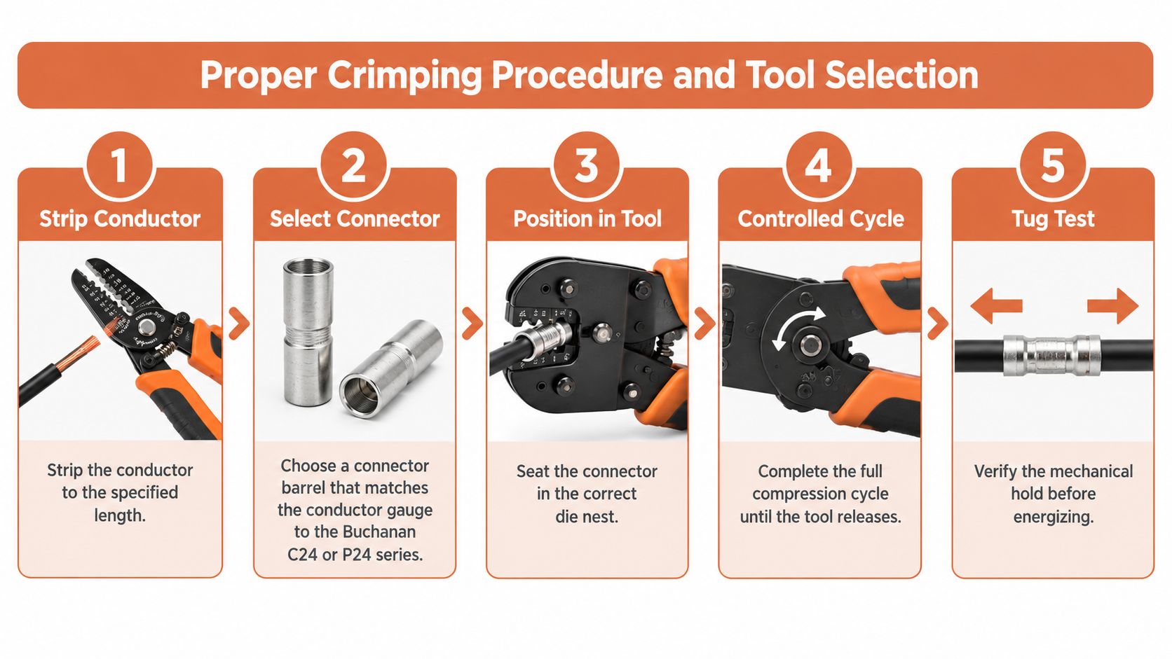
A reliable splice starts before the tool touches the connector. Confirm the connector family, conductor combination, and tool compatibility against the product documentation. Buchanan splice-cap listings identify the C24 or P24 pres-SURE tool for applicable models, including the 2006S, 2008S, and 2011S families.
A controlled installation sequence
Strip the conductor. Remove insulation to the specified strip length, commonly around 3/4 inch for the listed Buchanan splice-cap applications. Don't nick or reduce the copper strands, and don't leave excess bare conductor outside the cap.
Select the connector. Match the sleeve to the conductor material, gauge, and number of wires. For the families covered here, the relevant listings specify solid copper conductors. A connector that fits physically can still be wrong electrically or mechanically.
Insert the conductors fully. Bring the conductors together, insert them into the sleeve, and verify that the ends reach the intended insertion depth. Keep insulation out of the crimp area while preventing unnecessary bare copper from extending beyond the finished splice.
Seat the connector in the correct tool position. Place the splice cap in the appropriate C24 or P24 die position and engage the tool's latch or controlled-cycle mechanism. The latch setting controls how the tool completes compression, so don't substitute a guessed position.
Complete the cycle and inspect. Close the tool until the mechanism releases according to its designed cycle. Then perform the prescribed mechanical check, including a firm tug test, and flush-cut any protruding conductor ends where the product instructions call for it.
The cable ferrule crimping guide covers the same broader principle, namely that conductor preparation, die selection, and complete tool operation determine the finished connection. A partial squeeze isn't a controlled crimp. If the tool won't complete its cycle, remove the assembly and find the cause instead of forcing the handles or accepting the result.
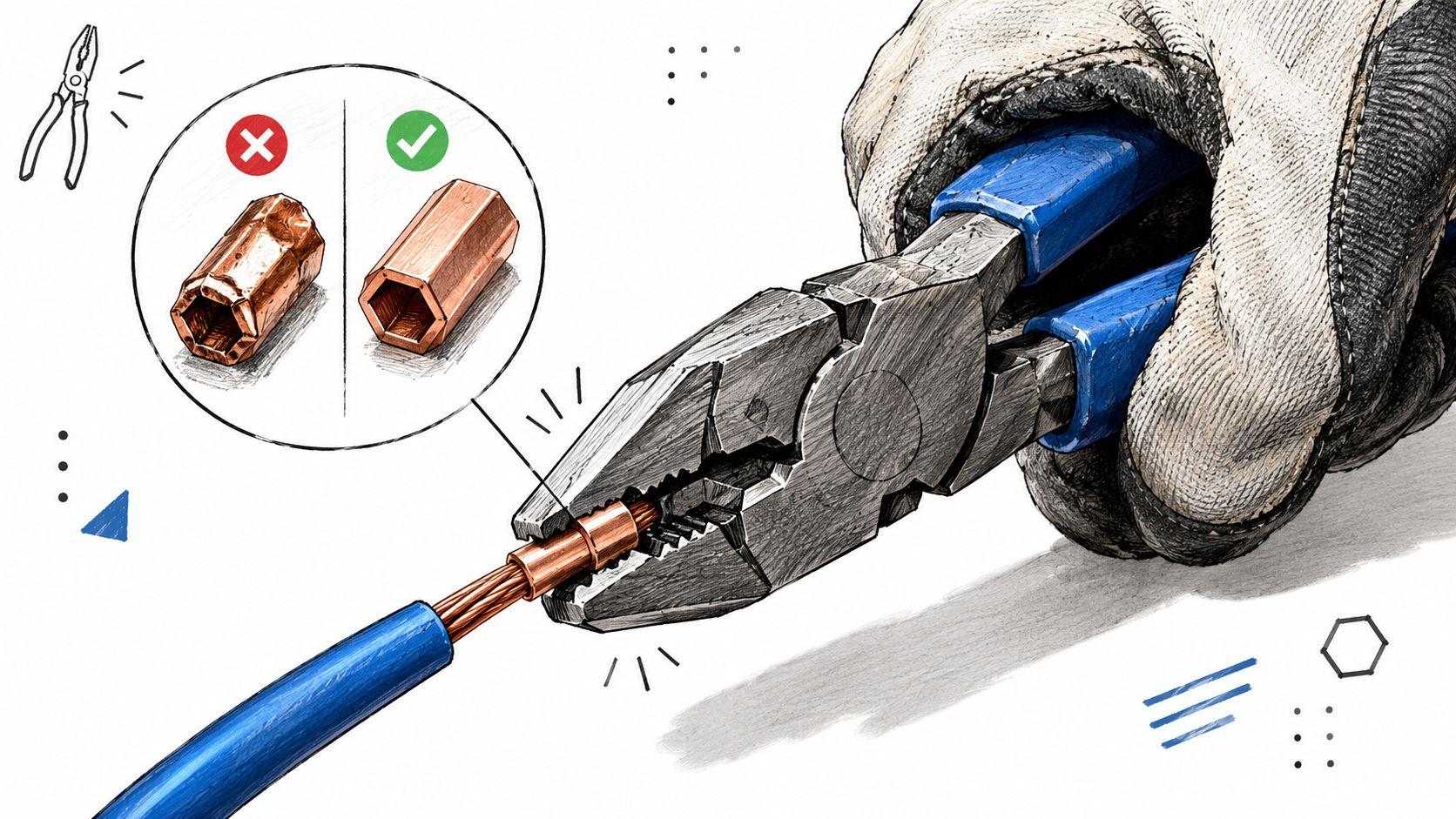
Lineman pliers are excellent for cutting, holding, twisting, and many general electrical tasks. They aren't a controlled-cycle crimper. The jaws apply force according to hand position and mechanical advantage, not according to a defined compression sequence and die geometry.
A splice made with generic pliers may appear tight while leaving uneven pressure around the sleeve. One side can be crushed more than the other, the conductor can shift inside the barrel, or the sleeve can be distorted without producing a stable mechanical hold. Visual inspection alone won't reliably distinguish a uniform crimp from a loosely formed one.
The practical issue is variation. Two installers can use the same pliers and produce different results, while one installer can produce different results as hand position, access, fatigue, and conductor arrangement change. A controlled-cycle tool reduces those variables by guiding the compression and requiring completion of the cycle before release.
What the shortcut costs
The common defense is that pliers are faster. They may be faster for one isolated squeeze, but rework, inspection questions, and inconsistent connections erase that advantage quickly on a production run. A distributor description specifically contrasts controlled-cycle uniformity with plier-made crimps, which is why the role of a dedicated PAT750Li crimper matters when the connector and application call for a different compression system.
For Buchanan splice caps, use the specified Buchanan C24 or P24 tool where the product documentation identifies it. Don't assume another crimper, a different die, or ordinary pliers will produce an equivalent result.
The following demonstration is useful for discussing tool technique with a crew, but it doesn't replace the connector manufacturer's installation requirements.
Matching Connectors to Circuits and Environments
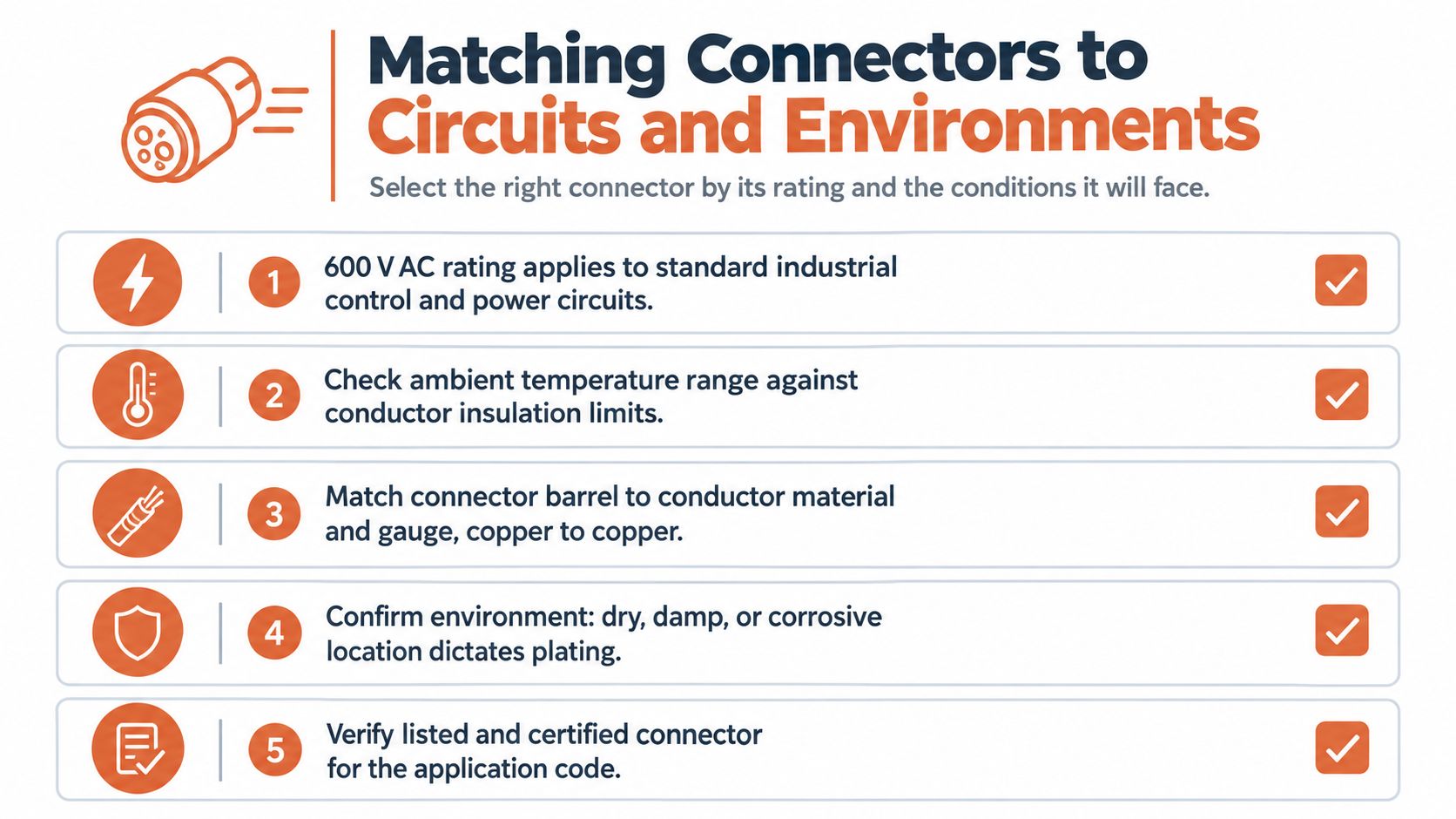
Connector selection should follow the circuit, not the other way around. A product's voltage rating, temperature limit, conductor range, and environmental suitability all have to agree with the installation.
Use this checklist during BOM review:
Confirm voltage. The 2006S and 2011S listings identify a 600 VAC or 600 V AC rating. That rating must still be appropriate for the complete circuit and installation.
Check temperature. The 2006S listing specifies a maximum operating temperature of 221 °F. Compare that limit with the actual location, nearby heat sources, conductor insulation, and enclosure conditions before placing a splice near a hot component.
Match conductor material and gauge. The covered families are listed for solid copper conductors. Verify gauge, conductor count, and the approved combination. Never treat a broad gauge range as permission to combine any wires within it.
Evaluate the environment. Vibration, moisture, chemicals, and corrosion exposure influence the connector and enclosure decision. The 2011S class is described as offering better corrosion resistance through its solid copper sleeve, but that doesn't remove the need for suitable enclosure and installation practices.
Verify documentation. Confirm the product listing, tool pairing, installation instructions, and project requirements before approving a connector or alternate.
For procurement teams, this checklist also helps separate a technically acceptable alternate from a visually similar part. If the original connector is unavailable, compare the conductor range, wire combination, rating, material, dimensions, listing, and required tool before requesting approval.
Practical Installation Examples by Application
A control-panel splice usually brings tight space and a high expectation for orderly workmanship. A 2006S-family connector may suit the conductor range when the wiring uses compatible solid copper conductors, but the installer still has to maintain the specified strip length and keep the completed splice clear of terminal blocks, sharp edges, and moving hardware. The C24 tool should be available at the panel, not improvised after the conductors are already prepared.
Branch-circuit and equipment wiring can involve larger conductors and greater mechanical exposure. The 2011S class covers larger wire sizes than the 2006S family, including published combinations such as two 10 AWG conductors at the minimum and two 6 AWG conductors at the maximum. That makes it a more relevant candidate for larger equipment or branch-circuit splicing, subject to the circuit design and applicable requirements.
Different job conditions, same quality controls
In an OEM panel assembly, repeatability is often more important than field convenience. Establish the approved connector and tool at the work instruction, train assemblers on the complete cycle, and inspect sample crimps before production continues. A connector that passes a quick visual check but spins on the conductor should be rejected.
A utility or facility repair can add vibration, restricted access, and pressure to restore service quickly. Those conditions are exactly when generic pliers become tempting. Prepare the conductors carefully, use the specified tool, verify the mechanical hold, and leave enough room for inspection and future maintenance.
For each application, the load and circuit design remain the engineer's responsibility. The crimp connector only addresses the splice. It doesn't correct an undersized conductor, poor routing, inadequate overcurrent protection, or an enclosure problem.
Compliance Context and UL CSA Listing Guidance
The UL 486C and CSA C22.2 #188 references associated with the 2006S listings indicate that the splice devices have been evaluated within the scope of those standards. For a contractor or inspector, that documentation supports the use of a listed permanent splice device when the product is installed within its ratings and instructions.
A listing isn't a blanket approval for every circuit. It doesn't replace conductor sizing, overcurrent protection, enclosure requirements, accessibility decisions, or the applicable NEC provisions for the installation. It also doesn't make an unapproved tool acceptable. The product, conductor combination, crimp tool, and installation method must remain aligned.
What to retain in the project file
During submittal review, request the current product data, listing information, installation instructions, and any tool compatibility documentation. Procurement should preserve those records with the BOM, especially when a project uses an alternate connector because of availability.
The product listing cited for the 2006S family places it in the common North American permanent splice category for low-voltage building and industrial wiring. That context is useful, but the authority having jurisdiction and the project's engineering requirements still control acceptance.
Inspectors should look for more than a familiar brand name. Check the connector family, conductor range, visible crimp, insulation clearance, and evidence that the installer used the specified process. A compliant component can still be installed incorrectly.
Troubleshooting Common Crimp Problems
Most crimp defects leave a physical clue. The key is to stop before energization or panel shipment, identify the cause, and replace the defective splice rather than trying to rescue a damaged sleeve.
Symptom
Likely cause
Corrective action
Sleeve spins or feels loose
Wrong connector range, incomplete cycle, or insufficient insertion
Cut out the splice and remake it with the approved family and complete tool cycle
Sleeve is flattened or split
Excessive force, wrong die, or incorrect tool
Discard the damaged connector and verify the C24 or P24 position
Bare copper extends too far
Strip length was excessive
Remove and restrip to the specified length
Insulation is inside the crimp area
Strip length was too short or conductor wasn't seated
Replace the splice and confirm full conductor insertion
Indent is off-center
Connector wasn't seated correctly in the tool
Reposition the connector and use the correct tool nest
Conductor pulls free
Wrong wire combination or incomplete compression
Replace the assembly, then verify the listing and cycle completion
Don't squeeze a loose connector again with pliers. That may hide the symptom while leaving the sleeve with an unknown compression profile. Permanent splices should be replaced when the crimp is suspect.
A tug test is useful for finding a weak mechanical hold, but it isn't a substitute for correct tool selection or product instructions. Inspectors and foremen should also look for nicked copper, damaged insulation, exposed conductor beyond the finished cap, and a connector body that has been crushed out of shape.
How to Choose the Right Buchanan Crimp Connector
Start with the conductor combination, not the connector package. Record the wire material, solid or stranded construction as applicable to the listing, gauge, number of conductors, and circuit rating. Then narrow the choice to a family whose published range and combination cover that arrangement.
Use the 2006S family when the documented application falls within 18 to 10 AWG solid copper, the connector's 600 VAC rating and 221 °F maximum operating temperature suit the installation, and the physical envelope works in the enclosure. Use the 2011S class for combinations within 14 to 4 AWG, including the published larger-conductor combinations, when the circuit and installation requirements support that choice.
A job-ready selection check
Validate the wire combination. Gauge alone isn't enough. Check conductor count and the manufacturer's published minimum and maximum combinations.
Confirm the ratings. Review voltage and temperature against the actual circuit and environment, not just the nominal project category.
Pair the connector with the tool. Confirm whether the job calls for a Buchanan C24 or P24 pres-SURE tool, and verify the correct latch or die position.
Plan the installation. Make sure the crew has stripping tools, the dedicated crimper, space for a complete cycle, and a way to inspect and test the finished splice.
Document alternates. When supply constraints force a substitution, compare listing, material, dimensions, conductor range, wire combination, and tooling before submitting it for approval.
That process gives engineers and contractors a clear basis for procurement decisions. It also helps purchasing teams avoid a common mistake, ordering a connector that fits the wire diameter but doesn't match the approved combination or available tool.
ATEK Distribution can help with connector and crimper sourcing, BOM review, product submittals, compliance documentation, and approved alternatives when an industrial project has a difficult lead-time or availability problem. Contact ATEK Distribution with the connector family, conductor combination, tool requirement, and project documentation so the sourcing team can help verify the material before it reaches the field.
The most common mistake with 500 kcmil aluminum cable is treating the 90°C insulation rating like a blank check. It isn't. The conductor may be able to survive a higher temperature column, but the actual feeder design is usually limited by terminations, installation method, and the equipment that has to accept the conductors without overheating or failing inspection.
That's why this size shows up so often in real feeder and service-distribution work. 500 kcmil aluminum sits in the large-conductor range used for commercial and industrial power distribution, and its published ampacity values make sense only when you match them to the terminal rating, raceway layout, and ambient conditions, not just the highest number on the chart. In practice, the design conversation is never “what can the cable theoretically carry,” it's “what can the full installed system support without creating a maintenance or compliance problem.”
A lot of spec sheets encourage a simple reading, if the insulation is rated for 90°C, use the 90°C ampacity. That shortcut causes trouble fast. The conductor might be capable of that thermal class, but the lugs, breakers, switchgear, and other terminations often set a lower limit that governs the actual feeder design.
Why the cable size matters more than the chart headline
Published NEC-based references list 500 kcmil aluminum conductors at 260 A at 60°C, 310 A at 75°C, and 350 A at 90°C under standard conditions, and a 2025 NEC-reference table shows 256 A, 304 A, and 344 A depending on insulation column, which points to the same practical reality, this is a large feeder conductor, not a magical free-pass wire (wire ampacity reference). Those values place the conductor squarely in the feeder and service-distribution range for commercial and industrial systems.
Practical rule: the conductor's insulation rating and the termination rating are not the same thing, and the lower one usually governs.
For engineering teams, that distinction matters more than the absolute top-line ampacity. If you're planning around the 90°C column without checking equipment markings, you can overspecify the cable or, worse, build a feeder that looks right on paper and fails at the terminal. The historical significance of NEC ampacity tables is that they standardized safe conductor selection across North America, so the skill that matters is reading the table the way inspectors and field electricians do, not the way a catalog headline does.
What this means in procurement terms
Procurement teams should treat 500 kcmil aluminum cable as a specification item, not a commodity size. The cable choice is only valid when it fits the terminal temperature class, the installation method, and the available cable routing space. That is where a BOM review catches expensive mistakes before material is ordered and scheduled.
Navigating Ampacity and the 75°C Termination Rule
The 75°C column is where most project teams end up, because that's often where the terminations land. The conductor may be rated for 90°C insulation, but equipment terminations commonly force the design back down to the lower practical column. That's why 500 kcmil aluminum is frequently treated as a roughly 300 A-class conductor in real feeder work, not just as a 350 A cable.
How the temperature columns actually behave
Independent reference tables list 500 kcmil aluminum at 260 A (60°C), 310 A (75°C), and 350 A (90°C), while manufacturer data for a related low-voltage cable shows DC resistance near 0.116 Ω/km at 20°C and ampacity around 310 A at 75°C and 350 A at 90°C in raceway or conduit applications (ampacity and resistance reference). In free air, the same size can be rated higher, with one manufacturer listing 545 A at 30°C ambient in a different installation condition, which shows how much installation environment changes the number.
Temperature Rating
Base Ampacity (Amps)
Typical Application Constraint
60°C
260 A
Lower terminal or equipment temperature class
75°C
310 A
Common termination limit in feeders and services
90°C
350 A
Cable insulation limit, not always the system limit
That table is the key to avoiding bad assumptions. The conductor can be perfectly fine at 90°C from an insulation standpoint, but if the breaker, lug, or switchboard is marked for 75°C, then the design has to respect the 75°C value. That's the bottleneck often overlooked.
Where overspecification sneaks in
The counterintuitive problem is that 500 kcmil aluminum is sometimes selected because someone wants headroom for a 90°C number, but the usable capacity collapses once the terminal rule is applied. In other words, the chart can make a conductor look larger than the actual feeder demand, and then the project team discovers that a smaller conductor class or a parallel arrangement would have been a cleaner fit.
A feeder doesn't fail because the cable had too little theoretical ampacity. It fails because the installed system couldn't use the ampacity that was on the paper.
For contractors and engineers, that means reading conductor selection as a whole-system exercise. For procurement, it means confirming the exact termination class and installation format before release, because swapping cable after rough-in can cost more than the material delta ever saved.
Applying Derating Factors for Real Installations
A base ampacity number is only the starting point. Real installations change the thermal picture immediately, and 500 kcmil aluminum cable is no exception. Ambient heat, continuous loading, and conductor grouping all cut into usable ampacity, which is why the same size can work in one project and be wrong in another.
The conditions that change the answer
The most common derating variables are straightforward, even if the calculations aren't. Hot ambient conditions, tight raceway fill, and underground burial all reduce heat dissipation, which means the conductor reaches its temperature limit sooner. In practical terms, that can push a feeder that looks adequate on a desk into a marginal installation once it's in a congested duct bank.
Field rule: if the installation traps heat, the allowable current falls. The cable doesn't care what the catalog says.
A 500 kcmil aluminum feeder may be acceptable in free air and still be undersized in a hot underground duct or tightly bundled raceway. That's why designers have to account for continuous-load expectations, conductor count in the raceway, and the ambient temperature at the actual installation point. The chart value is not the finished answer, it's the input.
The linked video below is useful for crews and project managers who need a fast visual reminder of how those environmental variables interact in the field.
How to keep the design honest
The safest approach is to derate first, then verify the load. That sounds basic, but it's where many late-stage submittal corrections come from. If you size to a headline ampacity and only later discover a hot mechanical room, a long burial run, or multiple current-carrying conductors in one pipe, the installation can turn into a change order.
The same logic applies to continuous load assumptions. If the feeder serves a duty cycle that runs hot for long periods, the cable has to be selected for the installed condition, not the ideal one. For project teams, that's a design review issue. For procurement, it's a reason to hold the order until the routing and termination details are locked.
Physical Properties and Job Site Handling
A catalog ampacity does not tell the crew whether a 500 kcmil aluminum cable will fit the route, survive the pull, or enter the termination without rework. Cable weight, outside diameter, bend radius, and pulling tension can control the installation schedule long before electrical calculations become the problem.
Medium-voltage builds are much heavier than the name suggests
Published data for a Nexans 15 kV XLPE design lists a 253 mm² conductor cross-section, 18.74 mm conductor diameter, 34.27 mm nominal outer diameter, approximately 1,474.99 kg/km weight, and a 535 A current rating in air at 40°C, with 370 A buried in duct at 20°C (Nexans 15 kV product data). A higher-voltage build for the same nominal conductor size can weigh substantially more while retaining a similar air rating because insulation and shielding add material.
That difference affects reel selection, unloading equipment, tray supports, and the pulling calculation. Confirm the cable's actual shipping weight and outside diameter before releasing the installation plan.
Construction changes more than just the outside diameter
One manufacturer sheet lists 37 strands for a 500 kcmil medium-voltage conductor. Another 500 kcmil design has an outer diameter of 38.29 mm, while a different insulation system reaches 40.67 mm (conductor construction data). Those dimensions affect conduit fill, roller selection, bend geometry, and the space available inside a termination enclosure.
ACAR 500 kcmil conductors are typically lighter and stronger than standard builds, so confirm the alloy family and minimum breaking load against the pulling plan before release. Do not substitute a conductor family based only on the shared kcmil designation.
If the reel arrives late or the pulling setup is improvised, damage can occur before the first termination is made.
Prepare the route before delivery. Verify reel orientation, pulling tension, allowable bend radius, lubricant compatibility, roller spacing, and support points. Termination lugs and equipment entry points also need a dimensional check. A focused guide to wiring strain relief can help when strain control and termination hardware are part of the scope. These checks are practical schedule protection, not paperwork.
Voltage Drop and Fault Duty Considerations
Ampacity alone does not make a feeder usable. Long runs with 500 kcmil aluminum cable still have to hold voltage at the load, and they still have to survive the fault current until the protection clears. Those two checks, voltage drop and fault duty, are where a design often gets changed late.
Resistance and reactance accumulate over distance
Manufacturer data for a 500 kcmil aluminum medium-voltage cable reports AC resistance at 60 Hz and 90°C of about 0.149 Ω/km, phase reactance near 0.15 to 0.17 Ω/km, and short-circuit capability of 29.3 kA for 1 second (MV cable electrical data). Those figures matter because voltage drop comes from both resistance and reactance, and long feeders magnify both effects.
The impact shows up in motor starting, equipment tolerance, and control stability. A conductor that passes ampacity checks can still cause trouble in service if the route is long enough. At that point the options are straightforward, shorten the run, upsize the conductor, or parallel conductors.
Fault withstand is part of the design, not a footnote
Fault duty has to be checked against the prospective fault current and the clearing time of the protective device. If the cable cannot survive long enough for the breaker or fuse to open, the design is not complete.
For plant work, coordinated fault response matters as much as the cable itself. A useful adjacent reference is plant-level electrical fault detection, because cable sizing and protection settings are tied together in actual installations, not handled as separate tasks.
The cable does not need to survive forever, it needs to survive until the protection opens.
Long feeders often trigger a second review for that reason. The correct fix may be a larger conductor, a shorter route, or a protection change. If impedance and fault duty are left until late submittals, the field crew usually pays for it.
Procurement Resilience and Supply Chain Risk
A lot of buying decisions still treat 500 kcmil aluminum cable as a simple cost-per-foot line item. That overlooks a significant risk. Availability now depends on upstream rod supply, utility electrification demand, and project timing, so the right cable can be hard to secure exactly when the crew is ready.
Availability is becoming part of the specification
Recent industry reporting says Hydro and Nexans signed a five-year agreement covering about 85,000 tonnes of low-carbon aluminum wire rod from 2026 to 2030, which points to a clear shift toward cleaner upstream supply for cable manufacturing (aluminum wire market reporting). The number itself matters less than the signal. Major manufacturers are planning around material flow, not just finished-product demand.
Market pressure is broader than one supply agreement. A 2026 Light Metal Age market report projects the global aluminum wire and cable market at $38 billion by 2026, tied to HVDC interconnectors, hyperscale data centers, and renewable utility connections (market report). Even if your job is outside those sectors, that demand affects lead times, approved alternates, and what is available in the channel.
Why procurement teams need a risk lens
Schedule protection is the issue. Large-gauge aluminum conductor programs can slip because of long manufacturing windows, unavailable insulation or jacket systems, or a late decision to accept an approved alternate. Teams that already reviewed alternates, submittals, and compliance paperwork are the ones that keep moving.
That kind of planning is where a sourcing partner helps. ATEK Distribution can support BOM review, manufacturer coordination, compliance documentation, and harder-to-source cable configurations, which matters when a specific build or reel size is not on hand. For a practical reference on managing volatility, the supply chain risk management guide is worth a look.
You can also use ATEK's supply chain reliability support as part of the procurement workflow when the cable spec is only one piece of a larger electrical package. It helps when material release has to line up with switchgear, protection, and installation milestones.
Executing Your Cable Procurement Strategy
A solid 500 kcmil aluminum cable purchase starts with four checks. Confirm the termination temperature class, verify the routing and installation method, lock the exact conductor construction, and review compliance paperwork before release. If any one of those is vague, the order is too early.
A practical release checklist
Confirm the terminal limit: Match the conductor to the lowest temperature-rated termination in the path, not the highest cable rating.
Validate the installation environment: Raceway fill, burial conditions, and ambient temperature all need to be known before final sizing.
Review the construction details: Insulation system, jacket, shielding, strand count, and overall diameter affect installability.
Align the procurement plan: Check availability, alternates, and delivery sequence before the field crew is scheduled.
That workflow is where distribution support earns its keep. ATEK Distribution can help with sourcing review, approved alternatives, and product documentation, and teams can also use where contractors source electrical equipment to coordinate the broader procurement path. If you're balancing material lead times against a live schedule, that coordination is often the difference between a clean release and a delay.
The right next step is simple. Get the feeder details, termination ratings, and submittal documents in front of the sourcing team before the purchase order goes out. That prevents the usual last-minute scramble, and it gives you room to substitute intelligently if the preferred build isn't on the shelf.
ATEK Distribution helps contractors, engineers, and procurement teams source 500 kcmil aluminum cable with the right documentation, availability, and alternates for the job. If you're working through feeder sizing, termination limits, or supply timing, visit ATEK Distribution to coordinate BOM review, sourcing support, and project-ready procurement help.
You're reviewing a one-line, the cable schedule is still moving, and someone has already asked for a wire cable tray part number. That's the wrong starting point. The tray decision should follow the run, not precede it: classify the cables and environment, calculate the working load, select the tray family, then lay out supports, fittings, bonding, and future access.
Wire mesh tray often earns the first look on indoor industrial, communications, and data-center runs because installers can load cables from the side, inspect the run quickly, and make field changes without threading cables through a closed raceway. But it isn't a universal answer. Heavy feeders, long unsupported spans, severe corrosion, and high concentrated loads can push the design toward ladder, solid-bottom, or another tray system.
Why Wire Cable Trays Are the First Decision on Most Industrial Runs
An engineer standing over a one-line usually needs to answer four questions in order:
What is in the run? Separate power, control, communications, fiber, and special-purpose circuits by cable construction, voltage, heat, and required separation.
What load will the tray carry? Use the cable schedule, not the empty-tray appearance.
Which tray family fits the work? Wire mesh, ladder, ventilated trough, and solid bottom solve different problems.
How will the system be supported and bonded? A correctly selected tray can still fail inspection or field acceptance if the support and grounding plan is incomplete.
Wire cable trays are particularly effective for indoor distribution runs with frequent cable additions. The open grid lets an installer drop or side-load cables at accessible points instead of pulling every new cable through a continuous enclosure. The same structure promotes airflow around the cable bundle, which is useful where power and communications cables share a managed corridor under the project's separation requirements.
The tray's low dead weight also simplifies bracket and trapeze work compared with heavier enclosed systems. That advantage matters in congested electrical rooms, overhead utility corridors, and data-center spaces where access is more valuable than a perfectly enclosed route. The open construction makes visual inspection easier too. A technician can see cable identification, bend conditions, unused capacity, and damaged insulation without removing a cover.
Know when mesh has lost the argument
Wire mesh becomes less attractive as the run becomes structurally demanding or environmentally aggressive. Heavy feeders may need the greater stiffness and deeper support structure of ladder tray. Long spans can require more supports than the project allows. Outdoor or corrosive environments may call for a material and finish selected specifically for exposure rather than a standard indoor wire product.
The category is formally standardized. In North America, metal cable tray systems are covered by NEMA VE 1 and installation guidance in NEMA VE 2, while IEC 61537 provides the international reference for cable tray and ladder systems, including wire mesh trays. NEMA VE 2 was later renumbered as NEMA BI 50016-2024, identified as the fourth edition, which reflects continued formal development rather than an informal product category.
Practical rule: Don't select mesh because it is easy to install. Select it when its access, ventilation, and changeability solve the actual constraints of the run.
Tray Types Compared for Real-World Applications
The fastest way to choose a tray family is to compare each one against the same field questions: how cables enter and leave, how the tray manages heat, how fittings affect the route, and whether the structure suits the expected span and load.
Tray Family
Cable Exit
Ventilation
Typical Span
Best Application
Ladder tray
Cable exits between rungs or over the side
Very good
Often preferred for longer, heavier runs
Large feeders, industrial power distribution, and runs requiring strong support
Ventilated trough
Side or top exit through perforated construction
Good
Moderate, dependent on load and profile
Control wiring, instrumentation, and general industrial distribution
Solid-bottom tray
Exit requires fittings, drops, or planned openings
Limited compared with open tray
Moderate, subject to loading and support design
EMI-sensitive routing, drip protection, and enclosed cable environments
Wire mesh tray
Side loading and exit through the grid
Very good
Moderate, dependent on product rating and support spacing
Data, communications, control, and mixed-power indoor runs with frequent changes
Where each tray family wins
Ladder tray wins when the cable mass is high and the route needs strong longitudinal support. It also provides straightforward access for large cables, but the rung arrangement can make small cable management and frequent branch-offs less tidy.
Ventilated trough is a practical middle ground for control and instrumentation. It offers a more continuous base than mesh while retaining ventilation. It can lose time on dense branch routing because installers may need more fittings or field openings.
Solid-bottom tray earns its place where cable protection, falling debris, or electromagnetic considerations matter more than maximum airflow. The trade-off is heat management and less convenient side loading. It shouldn't be treated as a default substitute for mesh in a high-change installation.
Wire mesh is usually the efficient choice for communications, fiber, and indoor mixed services. A broader cable-management overview, including how organized routing supports safer installations, is available in safer homes cable management. The link is residentially oriented, but the routing principles around access and organization transfer well to industrial planning.
For a mixed-services corridor, use mesh where the run is light to moderate and changes are expected. Reserve ladder for the feeder route, use trough for control groups that benefit from a continuous base, and use solid bottom only where its protection or shielding benefit justifies reduced ventilation.
Load Classes and Support Span According to NEMA VE 1
A tray rating becomes useful only after the run is classified and the cable schedule is calculated. Determine the installed cable weight per foot, identify the proposed support span, then select a tray class rated for the working load at that span.
NEMA VE 1 commonly uses these working-load designations: Class A is 50 lb/ft, Class B is 75 lb/ft, and Class C is 100 lb/ft. The class is tied to both load and support span, so one tray profile can have different ratings as the distance between supports changes. The Eaton NEMA-based cable tray specification gives a 20C tray example, rated for a 20-foot support span at 100 lb/ft.
The allowable load fraction is the portion of the published working load that the project permits. For example, using 0.8 reserves capacity for future additions. If the calculated cable load is 40 lb/ft and the selected fraction is 0.8, the required published capacity is 50 lb/ft, which corresponds to the Class A working-load value before checking the manufacturer's span and deflection data.
Use the rating for the exact tray width, depth, construction, and support span. Do not divide total project cable weight by the route length unless the load is genuinely distributed along that route. A concentrated bundle at a drop, reducer, splice, or fitting can control the design even when the straight section passes its load check.
Published class versus installed working load
The working-load value covers the cable load within the tested arrangement. It is not a target for filling the tray to the catalog limit. Future additions, uneven distribution, splice locations, and fittings reduce the margin available in the field.
Verify the manufacturer's tested span and deflection data during submittal review. Project documents may require a welded wire pattern to carry a uniformly distributed load over a defined span, tested as a simple span to NEMA VE 1. That requirement links the tray's published class to the actual support arrangement, rather than treating the class as a standalone product label.
Wire Mesh Cable Tray Specifications for Data and Power
Specify wire mesh tray by the conditions it must handle, not by its appearance. Classify the route first as data, control, or power. Then check cable size, heat dissipation, bend radius, environmental exposure, and required accessories before selecting the mesh, depth, width, finish, and support arrangement.
For communications work, confirm the opening against the selected manufacturer's cut sheet. A 3.7-inch by 5-inch welded wire pattern retains small cables differently from a 2-inch by 4-inch grid, and the opening can affect which divider strips and other accessories fit. The Panduit cable-tray specification illustrates the type of construction detail that belongs in a project specification. A denser grid can retain small cables more effectively, while a more open grid improves access and may provide fewer surfaces for dust to collect.
Construction details that affect installation
Project specifications may call for 4 mm or 5 mm wire, depths from 30 mm through 150 mm, and widths from 50 mm through 600 mm. Confirm each dimension against the manufacturer's product data. Nominal width and depth alone do not establish load capacity, deflection, or accessory compatibility.
The welded joint affects field work. T-welded and resistance-welded construction can respond differently when an installer cuts a side opening or modifies a section. Any cutout must protect the cables and retain joint strength. Remove burrs and sharp projections, and provide support near modified areas rather than relying on an improvised field cut.
Depth
Width Range
Wire Diameter
Mesh Pattern
Typical Finish
Application
30 to 150 mm
50 to 600 mm
4 or 5 mm, where specified
Open grid selected for cable size and retention
Zinc-plated mild steel or stainless steel
Indoor data, control, and power-support routes
Zinc-plated mild steel is commonly specified indoors. For corrosive exposure, evaluate 304 or 316 stainless steel against the actual environment. IEC 61537 provides the performance framework for cable tray systems, but the manufacturer must still identify corrosion classification and environmental suitability. Do not infer a C1 through C5 rating from the metal name alone.
Set cable fill to preserve space for heat dissipation, bends, drops, and future changes. Include Category 6A and single-mode fiber bend-radius requirements in the tray layout. Show splices, drop-outs, divider strips, and transitions on the plan so installers do not have to improvise around a loaded bundle.
Tray selection ends where support engineering begins. A wire mesh tray can meet its product rating and still produce a poor installation if the supports are too far apart, the bracket is undersized, or a fitting carries a load it was never intended to carry.
Common support arrangements include cantilever brackets, trapeze assemblies, and direct-mount brackets. Strut channel systems using 41 by 41 mm or 41 by 21 mm profiles can work with standard fittings, but the complete assembly must be checked for the tray width, cable load, bracket projection, and anchor condition.
Match the support to the load
Use the tested support spacing for the selected NEMA class and product. Light Class A runs may use shorter support spacing such as 1.5 m, while Class C applications may use 2.4 to 3.0 m spacing when the specific tray rating permits it. The field acceptance criterion is the manufacturer's stated deflection requirement, not a visual judgment made from the floor.
Provide additional support at reducers, tees, crosses, elbows, vertical transitions, and locations where cable bundles enter or leave the tray. Concentrated loads can control even when the straight section carries a modest uniform load. Expansion fittings and thermal transitions also need a planned location, with bonding continuity maintained across any movement joint.
Worked layout example
Consider a 9 m straight run of 300 mm wire mesh tray carrying 30 kg/m. The total distributed cable load is 270 kg across the run. That figure alone doesn't select the tray or support spacing, because the engineer must convert the project load to the applicable product rating and verify whether the stated load is uniform, whether accessories add weight, and whether the selected support centers are tested.
If the approved product allows the chosen span, lay out supports at the manufacturer's centers and place end supports so the tray overhang remains within the installation instructions. A 9 m route may require multiple support bays rather than a support at each end. Select a cantilever or trapeze bracket based on the 300 mm width, the total reaction at each support, and the structure available above the route.
Use conduit, raceway, and cable support products when coordinating the tray with adjacent raceway and support hardware. On site, verify anchor installation, bracket torque, tray level, splice alignment, and clearance from mechanical and process piping before the cable crew arrives.
Bonding and Grounding Requirements for Metallic Trays
A metallic tray is part of the electrical installation, not just a support shelf. The design must establish mechanical continuity, bonding continuity, and a documented grounding path under the applicable project requirements.
NEMA VE 2 states that metallic cable trays should be bonded to building steel and earth as supplemental grounding for ground-fault protection and signal-grounding noise prevention. It also identifies a maximum bonding interval of 18 m, or 60 ft, between bonded sections, as described in the NEMA VE 2 installation guidance.
The tray is not automatically the EGC
NEC guidance summarized by the Electrical Association grounding presentation permits a metallic cable tray to serve as an equipment grounding conductor only when continuous maintenance and supervision ensure that qualified people service the installed system and the applicable bonding provisions are satisfied. That condition is often misunderstood. Many industrial specifications require a separate green equipment grounding conductor even where the tray could qualify under the applicable code conditions.
Where a separate bonding jumper is required, size it under the applicable NEC rules, including the largest circuit overcurrent device used for the calculation. Provide jumpers across expansion fittings, flexible sections, and discontinuous segments. Use listed grounding clamps and listed splicers, and remove paint or nonconductive finish at contact points where the listed hardware requires metal-to-metal continuity.
Don't treat a bolted splice as proof of grounding continuity. Check the product listing, hardware, jumper requirement, and project specification together, then document the installed condition during the QA walk-down.
Routing, Fittings, and Installation Sequence
Start with the one-line and cable schedule, not the warehouse pile of tray. Plot the route, identify elevation changes, choose fittings, and only then release the material list.
Build the route before ordering fittings
Pull the one-line and cable schedule into the plan review. Plot the tray centerline, transfer it to the field with a laser level, and mark every riser, drop, ceiling transition, wall penetration, and equipment entry. A route that looks straight on the plan can require several elevation offsets once it meets ductwork, process piping, doors, structural steel, and equipment maintenance clearances.
Select factory elbows, crosses, tees, reducers, and drop-outs where the manufacturer provides them. Factory fittings preserve the intended geometry and cable protection. Field-fabricated miters can work when permitted by the manufacturer and project specification, but the cut must be smooth, structurally sound, and compatible with the cable bend radius. Keep bends within the manufacturer's limits. A 30-degree bend rule, where specified by the system, helps keep pull tension and cable bending under control.
At wall and floor penetrations, coordinate the sleeve, tray opening, fire-rated assembly, and annular space. Products such as 3M FB-3000 WT and Hilti CFS-IS may be used only where their listed system covers the actual wall or floor construction, cable configuration, and opening condition. The listing controls the permitted annular space and installation method. Don't substitute a sealant because its name sounds similar.
For cable pulling, stage reels so the cable enters the tray without a sharp reverse bend. Place rollers at bends and along long straight runs, with project practice often calling for rollers at every 30 ft and at each bend. Match the pull rope and pulling method to the tray length, cable cross-section, and manufacturer's cable-handling requirements. Before energization, complete the splice-hardware torque check and confirm that cables are supported without crushed jackets or violated bend radii.
The cable management category from ATEK can help consolidate tray, fittings, connectors, and related support items for a coordinated material release. For dense rack environments, a practical reference on managing dense rack cables is useful when the tray route transitions into cabinets and overhead rack pathways.
The video below provides a visual installation reference.
A QA walk-down commonly finds missing bonding jumpers at expansion joints, unsupported reducers, sharp field-cut edges, unsealed penetrations, poor tray level, loose splice hardware, and covers left off where the specification required them. Resolve those items before the cable installation hides the work.
Quick Reference for Wire Cable Tray Selection
Use this field card before releasing a tray bill of material. The sequence is deliberate: classify the run, size the tray for its load, select the tray family, then document supports and bonding. That order keeps the cable schedule, route, and installation requirements aligned.
Check
Field decision
Run classification
Identify power, control, communications, and fiber cables. Record the environment, required separation, bend radius, and allowance for future changes.
Load and span
Compare the calculated cable load with the selected product's working-load rating at the proposed support span. Confirm deflection limits from the submittal.
Tray family
Use mesh for accessible indoor routes, ladder for heavy feeder work, trough for many control cables, and solid bottom where protection or shielding outweighs reduced ventilation.
Show brackets, trapezes, reducers, vertical transitions, expansion locations, and structural attachment points on the layout.
Bonding and grounding
Identify listed splice hardware, jumper locations, bonding surfaces, grounding method, and whether the tray may serve as the EGC under the project rules.
Fill and working space
Calculate the applicable NEC fill requirement and preserve the required access around the route.
Standards check
Apply the NEMA class, tested span, installation requirements, and product documentation applicable to the selected system.
NEMA classes A, B, and C, with their respective working-load values, are defined earlier in this guide. Use that table for the class comparison, then confirm the tested span, deflection, fittings, and finish for the exact product under consideration. Classification and installation guidance follow NEMA VE 1 and VE 2. The international benchmark is IEC 61537, which specifies requirements and tests for cable tray and cable ladder systems used to support cables and potentially other electrical equipment in electrical and communication installations.
Before procurement, verify that the proposed tray can carry the actual cable schedule at the specified span. A rating that works on a straight run may not cover concentrated loads, fittings, vertical sections, or changes in support spacing. Resolve those conditions in the design rather than relying on field adjustments.
If the cable schedule is incomplete, hold the release. Obtain the missing cable sizes, quantities, route information, environmental requirements, and grounding criteria, then select a product family with documented load, finish, fittings, and compliance data.
ATEK Distribution can review a tray bill of material, source wire mesh tray and support hardware, coordinate manufacturer documentation, and identify approved alternatives when availability changes. Visit ATEK Distribution for project-specific sourcing, submittal support, and procurement assistance for industrial electrical infrastructure.