
You've just stripped a flexible conductor for a control panel terminal. The copper strands fan out, one slips under the clamp, and the finished connection looks acceptable until vibration or repeated heating exposes the weakness. A proper cable ferrule crimp prevents that failure by forming the strands into a controlled termination that the terminal can clamp consistently.
Appearance is only the first check. A reliable termination depends on the conductor, ferrule, die profile, crimp position, tool condition, and verification method working together. The useful question isn't whether the sleeve looks compressed. It's whether the connection matches the applicable requirements and withstands the pull force expected for its conductor size.
Table of Contents
- Why Cable Ferrules Exist and When They Apply
- Choosing a Ferrule Crimp Tool for the Job
- Preparing the Conductor and Ferrule
- Crimping the Ferrule End to End
- Inspecting the Crimp Against Pull Force
- Mistakes That Fail the Crimp Every Time
- When a Ferrule Is the Right Termination
Why Cable Ferrules Exist and When They Apply
A stranded conductor can fail at the terminal even when the insulation and copper look undamaged. Individual strands may spread under a screw or spring clamp, creating uneven pressure and leaving the connection vulnerable to movement and oxidation. A ferrule holds the strands in a metal sleeve, presenting the terminal with a defined contact area rather than a loose bundle.
Ferrules entered widespread European practice in the latter half of the twentieth century as manufacturers sought to protect stranded copper conductors at terminal screws. That purpose remains practical: the sleeve controls the conductor mechanically before the terminal applies clamping force. The relevant practice is reflected in the DIN 46228 series, along with EN 60999-1 and EN 60352-2, as outlined in Phoenix Contact's standards guidance.
Match the conductor before choosing the sleeve
Select the ferrule from the conductor's cross-section, not from color alone. Insulated ferrules use standardized dimensions and color identification under DIN 46228-1. Ferrules intended for fine-stranded conductors require the tighter dimensional considerations associated with DIN 46228-4. The sleeve should accept the entire strand bundle without folding strands, shaving copper, or leaving empty space inside the barrel.
Conductor construction also affects the termination. Fine-stranded cable contains more individual strands, so insertion and compression need closer control. A tinned end presents another condition because solder can stiffen the conductor near the clamp. Treat it differently from clean, flexible copper prepared for a ferrule.
Practical rule: Use a ferrule when a stranded conductor enters a screw or spring terminal rated to accept ferrules, especially in control, instrumentation, safety-related, or vibration-exposed work. Confirm the terminal manufacturer's instructions before making the method standard.
Ferrule families commonly cover conductor cross-sections from 0.5 to 50 mm², roughly AWG 20 to 1/0. The range describes the product family, not the capacity of one crimp tool. Check the ferrule and die ratings against the actual conductor size, then verify the finished termination with the applicable pull-force requirement. A sleeve that fits physically can still be the wrong choice if its dimensions, conductor class, or crimp profile do not match the terminal and tool.
Choosing a Ferrule Crimp Tool for the Job
The tool profile determines how the sleeve deforms, how evenly it compresses the strands, and how well the finished end fits the terminal. Three families cover most panel and harness work: square-profile ratcheting tools, trapezoidal-profile tools, and four-indent pneumatic or heavy-duty ratcheting crimpers.
A square-profile ratcheting tool is the practical daily choice for many control-panel benches. It's quick, relatively affordable, and the completed ferrule has flat sides that seat neatly in many spring and screw terminals. Its limitation is coverage. A die window may handle a useful group of conductor sizes, but it won't automatically make the tool suitable for every ferrule in the drawer.
Trapezoidal-profile tools produce a compact, repeatable deformation favored in many European panel-building environments. They can give a clean termination that inserts smoothly into spring terminals, but the tool and ferrule still need to be matched. A neat shape doesn't compensate for a die that's outside its rated range.
Four-indent tools compress the sleeve from multiple directions and can produce a strong, near-round termination for fine-stranded cable and demanding harness work. They cost substantially more than everyday hand tools, so the investment makes sense where the work involves production volume, fine-stranded conductors, or documented pull-force requirements. For occasional panel repairs, their capability may be unnecessary.
| Tool family | Typical AWG / mm² range | Crimp profile | Relative cost | Best fit for |
|---|---|---|---|---|
| Square-crimp ratcheting hand tool | Depends on the marked die window | Square | Lower | General control-panel wiring and service work |
| Trapezoidal-crimp ferrule tool | Depends on the selected die | Trapezoidal | Moderate | Repeatable European-style panel wiring and spring terminals |
| Four-indent pneumatic or ratcheting tool | Depends on the ferrule and die set | Four-indent, near-round | Higher | Fine-stranded cable, harness production, and documented quality programs |
Check more than the profile. The important details are the rated conductor range, handle force at that range, die marking, ratchet completion, and calibration basis. A tool that merely says “automatic” or “self-adjusting” isn't automatically compliant with a particular ferrule standard. Look for documentation connecting the tool and ferrule system to the required dimensions and test method.
For sourcing, ATEK Distribution's tools and testing selection is one place to compare crimping and verification equipment alongside the rest of a project's electrical requirements. The tool still has to be selected against the conductor, ferrule, terminal, and acceptance procedure.
Preparing the Conductor and Ferrule
A pull test can expose a preparation error before the ferrule ever reaches the terminal. Measure strip length from the ferrule collar and barrel depth, then adjust the stripper so insulation finishes where the collar can support it. The copper should extend only slightly beyond the sleeve shoulder. Phoenix Contact's technical guidance limits conductor protrusion to no more than 1 mm in its validation workflow.
Use a sharp, correctly adjusted stripper. A nicked strand reduces the conductor's strength, even when the defect disappears inside the barrel. After stripping, trim fanned strands cleanly. Do not twist them tightly or push loose filaments back into position.
Build the fit in a controlled sequence
Match the ferrule to the conductor cross-section and the specified ferrule family. DIN 46228-1 assigns a color band to each cross-section, and adjacent sizes such as 1.0 mm² and 1.5 mm² can look alike in poor light. Select from a labeled strip magazine or tray, then confirm the printed size against the manufacturer's documentation. For two conductors, use a twin ferrule rated for that arrangement rather than forcing both wires into a standard sleeve.
Inspect the barrel before insertion. It must be clean, undamaged, and free of deformation. The conductor should enter straight until the insulation meets the inside of the collar. Keep the fit dry: lubricants and flux can affect the termination, while residue or visible oxidation can interfere with reliable contact.
A strand folded backward inside the barrel creates a hidden void or stress point that may reduce measured pull force. ATEK Distribution's wire and cable range can help source the conductor alongside the ferrule specification when the materials need to remain under one controlled purchasing process.
Crimping the Ferrule End to End
Insert the prepared conductor fully into the sleeve. Check the collar first. The insulation should approach the collar without being trapped beneath the metal barrel, and no stray strand should escape at the entry. If the conductor doesn't slide in straight, stop and correct the strip or ferrule selection before applying pressure.
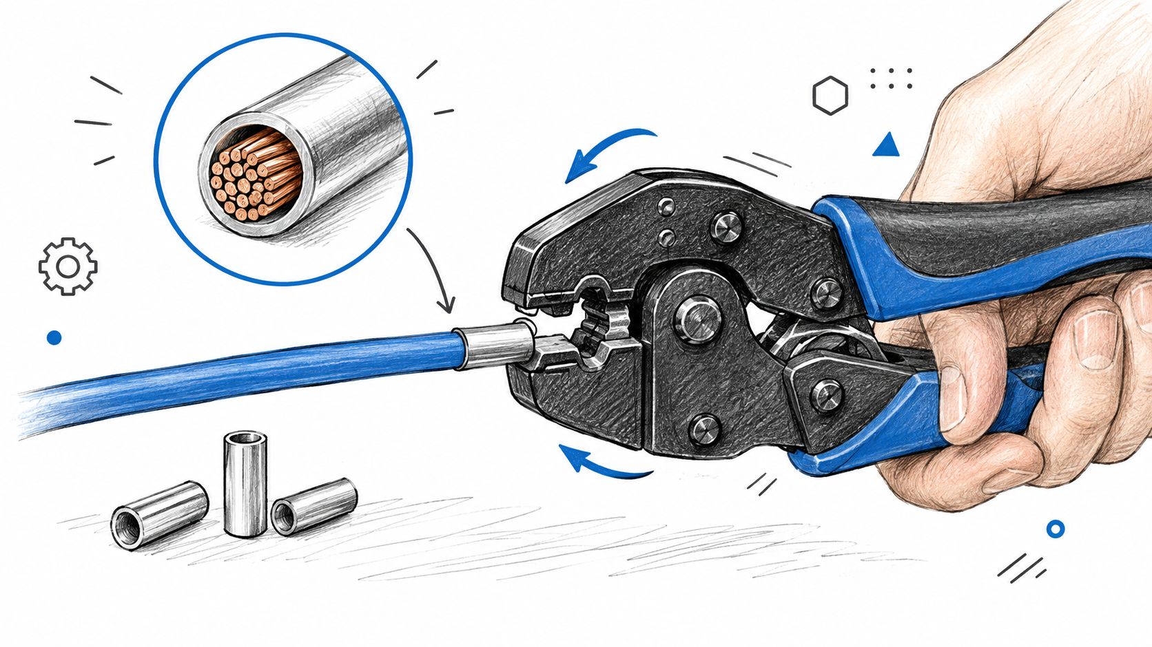
Place the ferrule in the die with the collar facing the correct direction and the sleeve centered in the rated crimp zone. The die should land close to the sleeve shoulder without crushing the plastic collar. Keep the crimp axis aligned with the conductor. A rotated or off-axis indentation can leave one side compressed while another side remains loose.
Close the tool through its complete cycle. With a ratcheting tool, don't reopen the handles halfway through and call the result finished. The ratchet exists to prevent partial compression, and the final release confirms that the designed stroke has been completed.
Control the compression across the sleeve
For larger sleeves or tools designed for multiple compression points, follow the manufacturer's sequence from the rear zone toward the front. The sleeve needs continuous support along its working length, not a single deep mark that leaves the rest of the barrel loose. Keep successive indentations in the same plane and re-square the ferrule before each compression when the tool requires repositioning.
A finished profile may be square, trapezoidal, or multi-indent depending on the tool. The profile should be even, with no fish-mouth opening, copper flash, split sleeve, or damaged collar. The wire should exit straight rather than bending sharply at the sleeve edge.
The Phoenix Contact crimping test guidance describes a validation approach in which the ferrule remains fixed under a target tensile load before the pull continues to failure. That is the standard to keep in mind while crimping. A clean shape is useful evidence, but it isn't the acceptance test.
A practical video demonstration can help operators see tool positioning and complete-stroke technique:
Inspecting the Crimp Against Pull Force
A pull test answers the question visual inspection can't. Does the conductor remain fixed in the ferrule under axial load, or does it slide before the connection reaches its expected strength? Standards-based ferrule practice ties quality to dimensions, tensile performance, and reliable contact formation, not to a crimp that merely looks symmetrical.
Published Weidmüller crimp tables provide these minimum pull-force values for selected conductor sizes: 10 N at 0.5 mm², 40 N at 1.5 mm², 60 N at 4 mm², 80 N at 6 mm², 100 N at 16 mm², 135 N at 25 mm², and 190 N at 35 mm². These values appear in Weidmüller's crimping documentation. Don't interpolate a value for an unlisted size and treat it as an approved requirement. Use the ferrule and tool manufacturer's table for the exact combination.
| Conductor Size | Minimum Pull Force (N) | Typical Failure Mode Below Threshold |
|---|---|---|
| 0.5 mm² | 10 | Conductor slips from an under-compressed sleeve |
| 1.5 mm² | 40 | Strand bundle moves inside the ferrule |
| 4 mm² | 60 | Partial compression or oversized die leaves a loose joint |
| 6 mm² | 80 | Sleeve deformation doesn't retain the conductor |
| 16 mm² | 100 | Incomplete compression or poor die match |
| 25 mm² | 135 | Large-conductor sleeve slips or fractures at the exit |
| 35 mm² | 190 | Insufficient full-length compression or tool mismatch |
Run the test as a controlled check
Clamp the ferrule or its test fixture without damaging the sleeve. Apply axial force with a pull gauge or load cell, hold the target load for the specified duration, and then continue at the prescribed rate until failure. The technical workflow described by Phoenix Contact holds the target load for 60 seconds and then increases the pull speed to about 25 mm/min. A passing connection remains fixed at the target load, while the conductor shouldn't pull out before the intended failure condition.
Visual inspection still matters. Check that the collar is intact, the indentation is symmetric, insulation isn't trapped beneath the barrel, and no copper has been shaved or pushed outside the sleeve. A crimp that looks excellent but falls below the applicable pull-force requirement is scrap.
NASA ultrasonic inspection research also shows why production teams shouldn't rely on appearance alone. One NASA study detected under-crimped terminations at a 97% detection rate, 93 of 96 samples, with a 1% false-call rate, 1 of 96, when ultrasonic transmission exceeded a threshold amplitude. The NASA report also connects ultrasonic amplitude changes with destructive pull-test outcomes. For routine bench work, calibrated tooling and destructive sampling may be sufficient. For higher-volume production, ultrasonic verification can add a non-destructive quality control layer.
Mistakes That Fail the Crimp Every Time
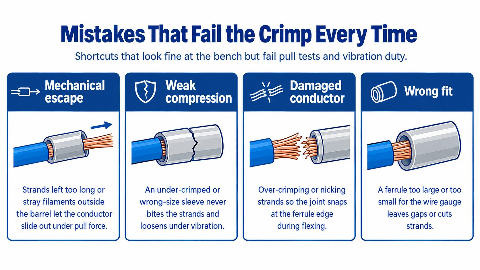
The failures that cause trouble are usually small and repeatable. A wrong strip length, mismatched die, or incomplete tool stroke can produce a termination that passes a casual visual check while failing under pull or vibration.
Start with the mechanical escape paths
A short strip leaves a gap between the conductor end and the sleeve nose. That reduces the supported length and gives the strand bundle room to move. An excessively long strip exposes copper beyond the sleeve, which can interfere with terminal clearance and create an avoidable electrical hazard.
A mismatched die fails in two directions. An oversized die leaves the strands insufficiently compressed, while an undersized die can shave strands, crush the collar, or force copper out of the barrel. The correct die window is the one specified for the ferrule and conductor, not the closest opening that happens to accept the part.
Look for compression defects
Rotated indents, partial handle closure, and skipped compression zones leave gaps in the sleeve. Those gaps may allow movement and oxidation, increasing contact resistance over service life. A complete ratchet cycle and consistent die alignment remove much of that operator variation.
Tool condition matters just as much. Worn jaws, loose pivot pins, contamination in the die, or a ratchet mechanism that no longer completes its designed stroke can produce weak crimps even when the operator follows the sequence. Inspect the tool when a pull test fails. Replacing the ferrule without correcting the tool only repeats the defect.
Protect the conductor before it enters the sleeve
A dull stripper can nick strands. Insulation left under the barrel prevents the sleeve from gripping the intended copper length. Pre-tinned conductors bring solder creep and a rigid transition into a termination designed for flexible strands. Tinning isn't a substitute for a ferrule in a screw or spring terminal.
A two-wire shortcut isn't a standard termination. If two conductors need to enter one terminal, use a correctly specified twin ferrule and matching tool, or use an approved terminal arrangement.
A standard ferrule isn't a license to cram two wires into one sleeve. The barrel, collar, conductor combination, and tool must be designed for that configuration. If the terminal needs separate conductors, use separate ferrules or an approved bridging method. If the application calls for a ring, fork, or specialized connector, use that termination instead of forcing a ferrule into the wrong hardware.
When a Ferrule Is the Right Termination
The decision starts with the terminal, not the tool drawer. A ferrule is usually the right choice when a stranded conductor enters a screw or spring-clamp terminal rated for ferrules, especially where vibration, repeated service, or consistent insertion matters. The terminal manufacturer's instructions remain decisive because some terminals specify a particular ferrule profile, conductor class, or insertion length.
Ferrules are particularly useful for flexible control wiring and fine-stranded conductors because they contain the strands before clamping. They're also preferable to solder-tinning a stranded end. Tinning creates a rigid section that can fracture or deform under clamp pressure, while a correctly selected ferrule preserves a controlled mechanical termination.
Use the application as the decision filter
Do not add a ferrule automatically to every electrical connection. A ring or fork terminal is the proper choice for a stud or screw designed for that lug. A direct termination may be specified for a connector that doesn't accept ferrules. A PCB pigtail may need a connector or soldered joint designed for that board, not a ferrule selected from a panel-wiring kit.
| Termination Method | Best Application | Standards Reference | Key Limitation |
|---|---|---|---|
| Insulated ferrule | Stranded conductor in an approved screw or spring terminal | DIN 46228-1, EN 60999-1 | Must match conductor size, terminal, and tool |
| Fine-stranded ferrule | Flexible or fine-stranded conductor requiring controlled clamping | DIN 46228-4, EN 60352-2 | More sensitive to sleeve and tooling mismatch |
| Twin ferrule | Two conductors entering a terminal approved for that arrangement | Applicable ferrule and terminal manufacturer requirements | Requires a correctly sized twin sleeve and die |
| Ring or fork terminal | Stud, busbar, or screw connection designed for a lug | Equipment and terminal requirements | Not a substitute for a ferrule in a cage or spring terminal |
| Direct conductor termination | Terminal specifically rated for the conductor without a sleeve | Terminal manufacturer's instructions | Strands can splay if the terminal isn't designed for them |
| Soldered pigtail | Board or component connection designed for solder | Product and assembly requirements | Not a replacement for a ferrule under a clamping terminal |
Standards guidance links ferrule quality to dimensions, test methods, and tensile performance. The Weidmüller ferrule reference is useful when translating that logic into a selection decision, but the equipment maker's terminal data should control the final choice.
For buyers, ATEK Distribution's wire termination and supplies can help consolidate ferrules, crimp tools, wire, and related termination products around a defined specification. Confirm the conductor cross-section, ferrule family, crimp profile, terminal model, and inspection requirement before placing a project-wide order.
A dependable cable ferrule crimp program is simple to state: match the sleeve, prepare clean copper, complete the correct die cycle, inspect the geometry, and verify pull performance against the applicable table. ATEK Distribution supplies electrical products and procurement support for contractors, industrial teams, facilities, utilities, and government buyers, including sourcing help for wire, cable, tools, and termination requirements. Visit ATEK Distribution to discuss the ferrules, crimping equipment, and project documentation your installation needs.