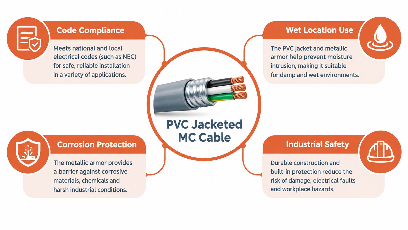
PVC-jacketed MC cable is a specific listed assembly under UL 1569 that combines metallic armor with an outer PVC sheath for wet or corrosive locations, governed by NEC Article 330. Depending on the insulation and construction, UL 1569 ratings extend to 600 volts for thermoplastic insulation and 600 or 2,000 volts for thermoset insulation, with conductor limits generally specified at 75°C or 90°C. Southwire's product documentation illustrates why the complete listing matters.
A contractor may receive a specification that says only “PVC jacketed MC cable.” The cable arrives, the jacket looks substantial, and the team assumes the substitution is complete. Later, the submittal review exposes a missing wet-location marking, an incompatible fitting, or a conductor insulation designation that doesn't match the installation.
That mistake is avoidable. A PVC jacket changes the cable's environmental role, but it doesn't erase the need to verify the armor, conductors, grounding method, terminations, temperature limits, and permitted installation method.
A cable can look ready for an outdoor run and still fail the submittal review. The phrase “PVC jacketed MC cable” describes a factory-listed cable assembly, not ordinary wire with plastic added afterward. Typical constructions combine copper or 8000-series aluminum conductors, THHN/THWN or XHHW-2 insulation, interlocked aluminum or galvanized-steel armor, and an exterior PVC jacket. UL 1569 covers round and flat armored cables with thermoplastic or thermoset insulation. Southwire's Type MC documentation shows why the complete construction and rating must be reviewed.
The jacket matters when a circuit leaves a clean, dry interior. Unjacketed MC may suit a dry exposed installation, while condensation, outdoor exposure, corrosive atmospheres, direct burial, or concrete encasement call for markings that specifically permit those conditions. PVC can improve resistance to moisture, sunlight, abrasion, and handling damage. It does not, by itself, establish every environmental rating.
What the jacket changes
The armor still supplies mechanical protection and, in a listed construction, may participate in the equipment-grounding path. The PVC layer shields that armor from moisture and corrosive contact. It also adds installation friction: a larger outside diameter can affect bending space, fittings, support, and termination preparation.
A jacketed cable is not automatically interchangeable with another jacketed cable. Check markings for wet locations, sunlight resistance, direct burial, concrete encasement, oil exposure, fire performance, and hazardous locations. Confirm the fitting is listed for the cable's actual outer diameter and assembly.
For sourcing comparisons, ATEK's wire and cable category is a practical starting point. Final approval should rely on the complete manufacturer datasheet and listing. The useful question is whether this exact assembly is listed for this exact installation.
Construction Layers and Core Components
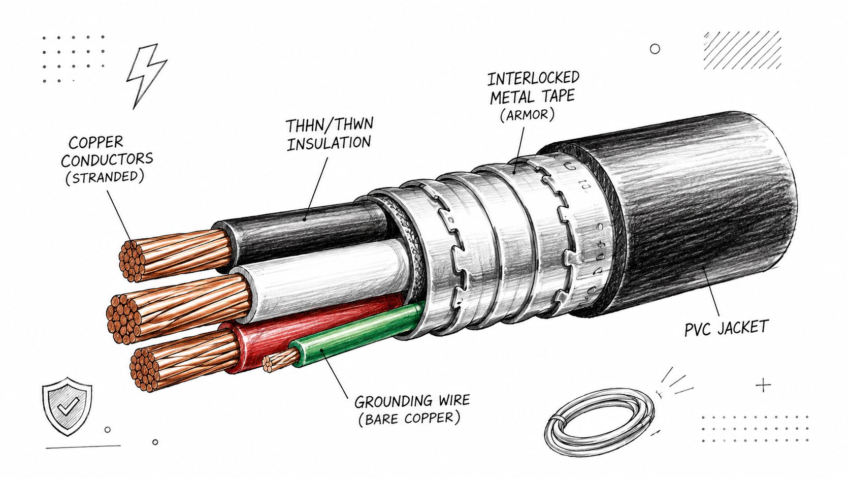
A PVC-jacketed MC cable has several functional layers, and each one answers a different installation problem.
Start at the center. The conductors carry the circuit load and are insulated with materials such as THHN/THWN or XHHW-2. The insulation designation affects dry- and wet-location suitability, temperature rating, and the ampacity calculation. Two cables with similar outside diameters can therefore have different permitted uses because their conductor insulation systems differ.
Around the insulated conductors sits the metallic covering. UL 1569 covers metal-clad cables with insulated conductors ranging from 18 AWG through 2000 kcmil, enclosed by interlocked metal strip armor or a smooth or corrugated metal tube, as summarized by UL 1569 construction information. The PVC jacket is an additional outer covering. It doesn't replace the armor or turn the product into nonmetallic cable.
Why each layer matters
Interlocked aluminum or galvanized-steel armor protects the conductors from ordinary handling and provides the cable's metal-clad structure. It may also provide an equipment-grounding path when the cable construction and fittings are specifically listed for that purpose. The nonconductive PVC jacket itself doesn't create grounding continuity.
The outer jacket protects the assembly from environmental contact, but it also changes the installation experience. The larger outside diameter can increase pulling friction and affect the space available at boxes, cabinets, and fittings. Cold conditions, tight bends, damaged jacket sections, and poorly prepared terminations deserve attention during installation.
A useful inspection sequence is:
Read the cable marking. Confirm the Type MC identification, conductor insulation, voltage rating, temperature rating, and environmental markings.
Check the armor. Verify whether it is aluminum or galvanized steel and determine how the equipment-grounding path is formed.
Match the fittings. Use connectors listed for the cable construction and grounding application. A connector selected for ordinary MC may not be suitable for every jacketed assembly.
Review the outer diameter. Confirm that the bend space, entry hardware, and enclosure capacity work with the actual cable.
Inspect the jacket after pulling. Cuts, crushing, and abrasion can undermine the environmental protection that justified the product choice.
The following installation overview is useful when crews need a visual reference for the cable's layered construction and handling:
NEC Code Requirements and UL 1569 Standards
Type MC requirements moved from NEC Article 334 in the 1999 edition to Article 330 in the 2002 edition. That change placed Type MC under its own article and clarified construction and installation provisions. Article 330 recognizes smooth metallic sheath, corrugated metallic sheath, and interlocking metal-tape armor as principal metallic-covering forms. Electrical Contractor's review of MC requirements documents this code history and the related environmental distinctions.
The practical consequence is simple. “Metal-clad” describes a family of constructions, not one universal environmental rating. Unjacketed MC could be installed in an other space used for environmental air under NEC Section 300.22(C), while wet-location installations required the metallic covering to be impervious to moisture or the insulated conductors to be listed for wet locations. A nonmetallic-jacketed MC assembly could be used in wet locations when the complete assembly was appropriately listed.
Read the listing with the installation method
Wet location, direct burial, and concrete encasement are not automatic consequences of seeing PVC on the outside. The cable must be identified for the specific method, and the installation still has to satisfy the applicable NEC edition, fittings requirements, support rules, physical protection provisions, and authority-having-jurisdiction interpretation.
UL 1569 sets the product framework. Under its fifth edition, published in 2018, covered ratings extend to 600 volts for thermoplastic insulation and to 600 or 2,000 volts for thermoset insulation, with conductor temperature limits generally at 75°C or 90°C depending on the design. Those figures identify possible listed ratings, not permission to apply one rating to every cable.
That distinction matters on temporary facilities as well as permanent plants. Teams coordinating a trailer-mounted office or field facility may benefit from reviewing mobile office trailer electrical requirements alongside the cable manufacturer's instructions and the governing electrical code. The installation environment, service arrangement, grounding, and local approval process still control the final decision.
For projects subject to a changing code basis, the applicable edition should be established before procurement. A Minnesota project, for example, may require teams to check Minnesota 2026 NEC changes as part of design review, inspection planning, and submittal coordination. Product compliance doesn't replace jurisdictional compliance.
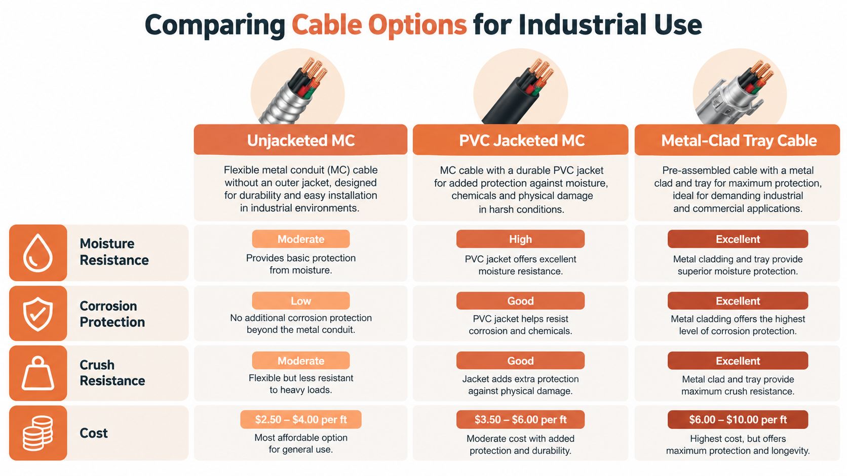
Comparing Cable Options for Industrial Use
The decision is not merely between cheap cable and expensive cable. It is between different combinations of environmental protection, mechanical behavior, serviceability, installation labor, and listing coverage.
Unjacketed Type MC can make sense in a dry indoor area where the cable isn't exposed to corrosive agents or persistent moisture. PVC-jacketed MC becomes more compelling when the route encounters condensation, sunlight, oil, corrosive exposure, direct burial, or concrete encasement, provided the exact product is listed for that use. Tray cable may be the better choice where the project already has a designed cable tray system and the cable's listing aligns with the tray, termination, and environmental requirements.
A practical selection view
Installation concern
Unjacketed MC
PVC-jacketed MC
Metal-clad tray cable
Dry indoor exposure
Often suitable when listed and protected from damage
May be more protection than needed
Depends on tray and cable listing
Moisture or condensation
Requires careful conductor and armor evaluation
Strong candidate when specifically listed
Depends on wet-location listing
Corrosive exposure
Limited by armor and environment
Jacket can add protection, but chemical compatibility remains essential
Requires cable jacket and tray system review
Direct burial or concrete
Not assumed suitable
Only when specifically listed
Depends on product and installation method
Future modifications
More difficult than conduit
Similar handling limits, with added jacket friction
Tray may simplify access if routing is already available
Material and labor trade-off
Lower material complexity in suitable dry areas
Added material and termination considerations
Requires supporting tray infrastructure
Some available PVC-jacketed MC constructions combine galvanized interlocked armor with a 50-mil PVC jacket, sunlight resistance, direct-burial or concrete-encasement listing, oil resistance, and operating limits of 90°C dry, 75°C wet, and -40°C minimum temperature, as shown in Atkore's product information. Those features belong to the identified product, not to every cable described as PVC jacketed.
Selection rule: Choose the least complex wiring method that still satisfies the actual environmental, mechanical, grounding, and serviceability requirements. Overspecification wastes budget. Underspecification creates failures that are harder to correct after installation.
Conduit remains attractive where physical damage is likely, future conductor changes are expected, or the project requires a rigid protective pathway. A related option such as one-inch flexible metal conduit may help with equipment connections, but its suitability depends on the complete raceway design and applicable fittings. PVC-jacketed MC is not a universal replacement for conduit, tray cable, or plain MC.
Ampacity, Termination, and Installation Risks
The most common technical mistake is treating a 90°C conductor rating as the final operating permission. PVC-jacketed MC products commonly use THHN/THWN or XHHW-2 conductors rated 90°C in dry locations, and XHHW-2 may carry a 90°C wet rating. The final ampacity still depends on adjustment, correction, terminal temperature, overcurrent protection, and the installation conditions described in Southwire's ampacity information.
Use the 90°C value as an engineering input when the applicable rules permit it, not as a blanket authorization. More than three current-carrying conductors, ambient-temperature correction, terminal limitations under NEC 110.14(C), and overcurrent-protection limits under 240.4 can all constrain the result.
Verify the calculation and the connection
A sound review follows the circuit from conductor to termination:
Conductor insulation: Confirm whether the cable contains THHN/THWN or XHHW-2 and whether the wet rating matches the location.
Ampacity basis: Apply the relevant NEC table, adjustment factors, correction factors, and small-conductor limitations.
Terminations: Check the temperature rating and wire range of lugs, breakers, disconnects, terminal blocks, and other equipment.
Fittings: Use connectors listed for the specific MC construction and grounding function. The jacket may require a different entry arrangement or stripping procedure.
Grounding path: Confirm whether the assembly contains an internal equipment-grounding conductor, uses listed armor for grounding, or requires another bonding arrangement.
Pulling is another place where the jacket creates trade-offs. The outer covering can increase friction and outside diameter, especially in long or crowded routes. Pulling tension, bend space, cold-weather handling, and entry alignment should be considered before the cable reaches the jobsite. A jacket that arrives intact can still be damaged by a sharp edge, excessive force, or a bend tighter than the manufacturer permits.
Termination workmanship deserves its own inspection. Remove the jacket and armor only as instructed, preserve conductor insulation, install compatible fittings, and verify that seals and bonding components are fully engaged. A watertight-looking entry isn't necessarily a listed wet-location termination.
The same discipline applies to low-voltage and security pathways. For teams coordinating power with CCTV and alarm installation Melbourne, cable routing, enclosure entry, environmental exposure, and separation should be coordinated rather than handled as isolated trades. The product category may differ, but poor pathway planning creates the same type of access and inspection problems.
Procurement and Sourcing Support at ATEK
A technically correct cable can still become a procurement problem if the requested description omits the information needed to identify the assembly. “PVC jacketed MC cable” should be treated as a starting phrase, not a complete purchase order line.
A useful submittal package should identify:
Conductor details: Copper or 8000-series aluminum, conductor size, strand construction where relevant, and insulation designation.
Cable rating: Voltage, conductor temperature, wet or dry suitability, and any limits that affect the design.
Armor construction: Aluminum or galvanized steel, interlocked or other permitted form, and the grounding method.
Environmental listing: Sunlight, corrosion, oil, direct burial, concrete encasement, firestop, or hazardous-location suitability when required.
Documentation: UL 1569 listing information, manufacturer datasheet, installation instructions, and any jurisdiction-specific submittal requirements.
The procurement team should compare the proposed cable against the approved basis of design, not just against conductor size and voltage. During shortages, an alternate may look equivalent while differing in jacket thickness, wet-location status, armor material, temperature limits, grounding construction, or permitted installation method.
ATEK Distribution can support BOM review, manufacturer coordination, hard-to-source component searches, alternate evaluation, product submittals, compliance documentation, and project staging. That role is useful when an engineer needs a technically defensible substitution or when a contractor must keep a mission-critical installation moving without losing control of the approved materials.
The best sourcing process also checks the accessories. A cable and fitting combination should be reviewed as an installation system, especially where the jacket affects entry dimensions, stripping, seals, firestop, or bonding. A complete material review prevents the familiar outcome where the cable is available but the listed connectors are not.
For PVC-jacketed MC cable, ATEK Distribution offers product sourcing, BOM support, approved-alternate evaluation, and documentation review for the cable and associated electrical components. Visit ATEK Distribution with your cable schedule, environmental requirements, and submittal criteria so the sourcing team can help verify the complete assembly before it reaches the jobsite.
Most advice on conduit stainless steel gets the first half right and the second half wrong. The tube matters, but the installation usually fails at the joints, the supports, the fittings, or the alloy choice that looked fine on paper and proved wrong in the field. If the raceway has to survive washdown, salt air, chlorides, chemicals, or repeated maintenance access, the product that counts is the complete raceway assembly, not the stick of conduit.
That matters because stainless steel is not a magic shield. It is a durable, corrosion-resistant material with clear strengths, but its performance still depends on the environment, the grade, the finish, and what it touches. For engineers, contractors, and procurement teams, the job is to spec the whole system so the conduit doesn't become the weakest link in an otherwise resilient installation.
A lot of bad installations start with a good assumption pushed too far. Stainless steel resists corrosion far better than ordinary coated steel in harsh, wet, chemical, food-processing, healthcare, utility, and infrastructure environments, but threads, cut ends, bends, and field-made transitions can still become failure points. The conduit body may last for years while the joints turn into the maintenance problem.
Practical rule: if the spec only says “stainless steel,” the job is still under-defined.
The National Electrical Code materials provisions also steer designers away from dissimilar-metal contact where practicable because galvanic action can speed attack at joints. A bare stainless tube paired with mismatched hardware can underperform a coordinated system built from compatible parts. The tube is rarely the first failure point, the interface usually is.
Treat stainless conduit as infrastructure, not commodity
For procurement, stainless conduit should be handled as an internationally sourced infrastructure product with lead time, alloy, and documentation questions, the way you would treat switchgear, not as a simple line item. The global stainless-steel melt production data for 2024 shows that the raw-material base is widely distributed rather than tied to one regional source chain, which affects availability and sourcing risk for projects that need resilient electrical raceways (global stainless-steel production overview).
The most reliable jobs I've seen start with three decisions made early, not in the field:
Grade selection, so the alloy matches the exposure.
Accessory matching, so fittings, boxes, and supports do not undo the corrosion resistance.
Documentation review, so listings and installation details are aligned before material ships.
Handled up front, those three choices keep stainless steel conduit doing what it should, supporting a long-life raceway system in aggressive service. If the alloy, fittings, and paperwork do not match, the assembly behaves like a compromise.
Choosing Between 304 and 316 Stainless Alloys
Start with the environment, not the price delta
The wrong way to choose between 304 and 316 is by calling one "standard" and the other "premium." The right way is to test the site against the chemicals, moisture, temperature, and contamination risk that the raceway will see. Both alloys cover a broad range of service conditions, but 316 has molybdenum, which gives it better resistance to pitting and crevice corrosion in chloride-rich or otherwise aggressive environments (304 vs. 316 selection guidance).
That distinction matters on coastal sites, road-salt exposure, wastewater areas, and washdown zones where chloride-bearing moisture lingers at fittings and clamps. It also matters where cleaning chemicals are part of the operating routine, because the conduit is exposed to more than ambient humidity. A nameplate like “wet location” doesn't tell you enough.
A practical selection matrix
Environmental Factor
304 Stainless Steel
316 Stainless Steel
Indoor washdown
Often suitable when chemistry is mild and cleaning is controlled
Use when cleaning agents or residue are more aggressive
Coastal or road-salt exposure
Less forgiving if chlorides collect at joints
Stronger choice because of better chloride resistance
Wastewater and process areas
May work in lighter exposure, but verify chemistry
Better fit where corrosive moisture and residue persist
High-temperature service
Can lose performance in certain acidic or alkaline conditions
More robust, but still requires environment review
Dissimilar-metal contact
Still needs careful accessory matching
Still needs careful accessory matching
The same caution applies to other stainless products in sanitary environments, where cleanability and corrosion exposure drive material choice. A related example is browse stainless cleanroom shelving, which shows how buyers in controlled environments often evaluate finish, compatibility, and maintenance access together rather than treating stainless as a one-word answer.
What to ask before you spec either alloy
A good submittal review should force the conversation past guesswork:
Chloride exposure, including road salt, coastal spray, and washdown residue.
Temperature range, because heat changes corrosion behavior.
Cleaning chemistry, especially in food, healthcare, and process plants.
Crevice risk, which is often highest at fittings and supports.
Galvanic exposure, especially where stainless meets aluminum, galvanized steel, or copper.
304 is often the sensible choice where the environment is controlled and the chemistry is mild. 316 earns its keep where chloride attack, persistent moisture, or aggressive cleaning makes the connection points vulnerable. The key is to specify the actual environment, not a generic label.
Navigating NEC Articles and UL Listing Requirements
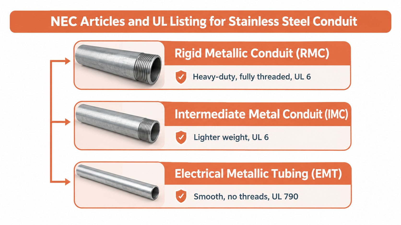
Stainless conduit does not live under one generic rule set. The spec has to follow the raceway family, because Rigid Metal Conduit is covered under UL 6A, while Electrical Metallic Tubing is covered under ANSI/UL 797A for aluminum and stainless-steel EMT used as metal raceways under NFPA 70. Those are different constructions, and a stainless finish does not make them interchangeable (UL 6A listing scope).
The NEC treats them by article as well. RMC is addressed in Article 344, IMC in Article 342, and EMT in Article 358. Installation rules, fitting requirements, support intervals, and field-use limits do not carry over from one raceway type to another (NEC corrosion and raceway requirements).
What inspectors and submittal reviewers check first
The fastest way to avoid a rejected submittal is to prove the assembly, not just the tube.
Exact raceway type, because RMC is not EMT and EMT is not IMC.
Trade size, since UL 6A and UL 797A cover defined size ranges.
Compatible elbows and fittings, because the tubing listing alone is not enough. If the drawing says stainless RMC, the submittal has to prove that the elbows, couplings, and nipples match that raceway family, starting with compatible 90-degree elbows.
Installation instructions, because the manufacturer's limits still govern the field work.
Markings and documentation, especially on public, healthcare, industrial, and mission-critical jobs.
BOM review matters because most problems start with the accessory package. A change in availability does not justify mixing a listed raceway with unlisted fittings or a different raceway family. If the assembly is being revised, the alternate has to be checked as a complete system, not just as a stainless substitution.
Field lesson: inspection delays usually come from a mismatch between the listed raceway and the accessory package, not from the conduit body itself.
Bend layout deserves the same attention. The NEC limit of 360 degrees of bends between pull points is a design checkpoint, not a suggestion (NFPA code-development material). If a run exceeds that limit, the pull point has to be built into the raceway plan before the conduit is ordered.
Preventing Galvanic Corrosion at Connections
The raceway usually fails where metals meet
Galvanic corrosion starts when dissimilar metals touch in an electrically conductive environment, such as saltwater or persistent moisture. Stainless steel connected to aluminum, galvanized steel, or copper can become part of that circuit, and the less noble metal usually corrodes first (galvanic corrosion guidance). The conduit body may be sound. The joint, fitting, or support often is not.
That is why the raceway assembly deserves more attention than the tube alone. A stainless run with the wrong connector, a mixed support package, or unapproved hardware can lose its corrosion resistance at the exact point where water sits and current can move. In wet or chloride-heavy service, mixed accessories are where field failures start.
Build the whole assembly with that risk in mind. Keep metals close on the galvanic series where practical, isolate joints when the design allows it, and avoid substituting whatever happens to be on the shelf. A complete stainless raceway and support package usually beats a patchwork of mixed parts when the environment is aggressive.
Match the fittings, hardware, and field work to the raceway
The specification should name the stainless grade, the finish, and the accessory family together. Elbows, couplings, boxes, enclosures, straps, connectors, locknuts, hubs, and bonding hardware all need to be compatible with the raceway, not merely made of metal. For threaded field work, the NEC requires an approved electrically conductive, corrosion-resistant compound where corrosion protection is needed and the threading occurs outside the factory-listed process (UL service guidance).
Support points need the same discipline. A stainless conduit run can still fail early if it lands on incompatible straps or a mismatched enclosure, because those parts see moisture, vibration, and repeated maintenance contact. In mixed-metal environments, a sourcing review should cover the entire assembly, including the right rigid and IMC fittings from a dedicated catalog such as electrical conduit fittings.
A short field checklist keeps the assembly honest:
Match materials at couplings and terminations.
Isolate dissimilar metals where the design and code conditions allow it.
Verify bonding continuity at threaded joints and transition points.
Avoid ad hoc substitutions that break the listed system.
Review exposed hardware because supports and straps often start the corrosion.
The goal is a raceway that stays electrically continuous and corrosion-resistant after the first washdown, the first maintenance cycle, and the first repair.
Industrial Applications and Lifecycle Cost Tradeoffs
Stainless costs more up front, and that's not the whole story
Coated steel can look cheaper on a quote. On site, the bill changes fast when a cut edge, thread, or bend loses its coating and corrosion starts. Stainless steel removes that coating dependency, which is why it holds up in coastal infrastructure, chemical service, food and beverage plants, wastewater facilities, and outdoor washdown areas.
Global melt production of roughly 62.82 million metric tons in 2024 confirms stainless as a mainstream industrial material with a broad, globally sourced supply base. China accounted for about 39.44 million metric tons, or roughly 62.8% of worldwide output (global stainless-steel production overview). For conduit buyers, that scale matters because stainless raceways are supported by a wide materials market, not a narrow specialty channel.
Where stainless usually earns its place
The strongest cases are easy to spot once first cost stops driving the conversation.
Coastal and marine work, where chlorides attack weak points.
Wastewater and treatment areas, where moisture and chemicals stay on the hardware.
Food-processing and sanitation zones, where washdown is routine.
Utility and infrastructure projects, where service life matters more than cheap replacement.
Healthcare and clean operations, where documentation and maintainability count.
Stainless is a poor fit for every mild indoor run. A dry, low-exposure installation does not need the same alloy, accessories, or submittal burden as a salt-exposed shoreline site. Good specification means matching the raceway to the exposure, then keeping the fittings, boxes, and supports aligned with that choice.
Lifecycle cost usually comes down to one issue: if a material depends on a coating, installation damage or later maintenance can create a hidden failure mode. Bare stainless avoids that dependency, but only when the complete raceway assembly is treated as one system.
Sourcing Complete Stainless Raceway Assemblies
Procurement has to validate the whole BOM
A conduit purchase order that stops at the tube is incomplete. The actual sourcing task is the whole assembly, because elbows, couplings, locknuts, hubs, supports, and bonding hardware have to match the stainless grade and the listing family. If one item is substituted casually, the entire raceway can become a mixed-metal compromise.
That's where a systems-level sourcing partner helps. ATEK Distribution can assist with BOM review, product sourcing, alternate product evaluation, and compliance documentation when stainless conduit components are short, delayed, or regionally constrained. The practical value is not just availability, it's keeping the submittal aligned with the actual raceway you can build.
For project teams managing conduit, raceway, and cable support together, a consolidated source can reduce rework and split shipments. A useful starting point is conduit, raceway, and cable support, especially when the stainless raceway is part of a larger electrical package that also includes supports and accessories.
What to confirm before release
Before you authorize procurement, verify these points together:
Raceway type and listing, so the material matches the standard.
Alloy and finish, so the corrosion resistance matches the site.
Accessory compatibility, so fittings and boxes don't undercut the system.
Documentation package, so submittals and inspection records are ready.
Approved alternates, so shortages don't stall the project.
That approach keeps mission-critical jobs moving when one component is unavailable. It also avoids the classic mistake of approving a substitute conduit and then discovering that the elbows, fittings, or enclosures don't share the same corrosion or listing profile.
If you're sourcing conduit stainless steel for a corrosive or mission-critical project, ATEK Distribution can help review the BOM, confirm accessory compatibility, and identify approved alternatives before material release. Visit ATEK Distribution to request sourcing support, check availability, and keep your raceway package aligned with the job spec.
The most common advice on Buy American Act compliance is the least useful one: check for a “Made in USA” label and move on. That shortcut might satisfy a casual buyer, but it won’t hold up when a contracting officer asks for component origin, delivery-period applicability, or proof that the product category was tested under the right rule.
For electrical contractors, that gap matters on every package that includes switchgear, transformers, controls, wire, lighting, enclosures, or fabricated assemblies. Compliance turns on the product-level evidence chain, not the marketing label, and the only safe way through it is to tie each line item to the clause, the bill of materials, and the supporting records.
A domestic label tells you where a product was assembled, not whether it clears the federal domestic-content test. Under Buy American Act compliance rules, that distinction is the difference between a submittal that passes review and one that gets kicked back for missing documentation.
Assembly and component cost are different tests
For most federally acquired supplies and construction materials, the governing test is based on domestic component cost, not just final assembly. The current rule structure uses more than 60% domestic components historically, 65% for items delivered during calendar years 2024 through 2028, and 75% for items delivered beginning in 2029. That staged change matters because a product that was acceptable on an earlier project may need new sourcing or better records for a later delivery date. Buy American Act domestic-content requirements
Practical rule: if the submittal package stops at the manufacturer’s country-of-assembly statement, the file is incomplete.
Electrical gear is where this gets messy fast. A switchboard or control panel can look domestic from the outside while still carrying components from multiple countries, and components of unknown origin are treated as foreign under the standard construction-material clause. That makes traceability a procurement issue, not just an engineering issue.
Why documentation has to follow the product
A single manufacturer letter rarely solves the whole problem. For complex electrical equipment, the buyer needs a record that connects the product, the component makeup, the delivery window, and the applicable contract clause. That’s also why guidance on navigating global compliance certification is useful here, because the compliance burden sits in the evidence trail, not the label.
If you’re reviewing a BOM for a federal project, treat every item as a question: what exact rule applies, what date does delivery occur, and what proof exists for the origin of the parts inside the product? That’s the level of detail auditors expect, and it’s the level that keeps submittals from stalling.
Calculating Domestic Content Thresholds
The test begins after the label check. For federal electrical work, the calculation changes with product type, and the first question is whether you are dealing with a general manufactured supply or a construction material with significant iron or steel content.
What belongs in the calculation
For electrical assemblies, the bill of materials matters more than the marketing sheet. Component cost can include transportation, duties, and allocable overhead under the federal framework, while final-product manufacturing cost does not. That shifts the result depending on how the supplier built the record and what it can support.
A panelboard can look straightforward until you break it into the parts that count. If the BOM shows domestic enclosure fabrication, but the breaker kits, buswork, harnesses, and control devices came from multiple sources, the percentage can move quickly once freight, duties, and other allowable component costs are included. A file that ignores those costs may understate the domestic share, while a file that pads the wrong items can fail the audit just as easily.
A compliant BOM is more than a parts list, it is a cost story tied to each component.
That is why procurement teams should review the product-level evidence chain, not just a manufacturer letter. The goal is to tie each line item to origin support, cost support, and the exact product delivered under the contract. On a federal submittal, that is the difference between a clean review and a stalled package.
Iron and steel need a separate check
Products consisting wholly or predominantly of iron or steel are tested under a different rule. Under the cited construction provision, foreign iron and steel must stay below 5% of the cost of all components used in that construction material. Construction material iron and steel rule
That is a narrower test than the domestic-component calculation used for other covered supplies and materials. The practical risk is mixing the two. A team can do the general percentage correctly and still miss the iron and steel rule if the assembly is treated like ordinary equipment instead of a covered construction material.
For contractors reviewing electrical gear, the safest approach is simple. Match the product to the clause, total the component costs with the right treatment for freight and duties, and keep origin records for every part that will be questioned in an audit. When a supplier cannot prove a component’s origin, treat it as a foreign component and correct the BOM before the submittal goes out.
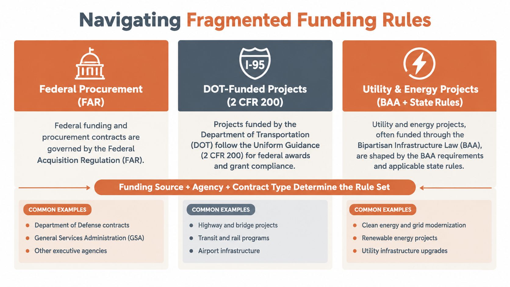
Navigating Fragmented Funding Rules
Buy American Act compliance is not one universal checklist. The rule set changes with the funding source, the agency, and the contract clause, which is why the wrong assumption can be more expensive than the wrong part number.
Three common frameworks buyers confuse
For direct federal procurement, the Federal Acquisition Regulation drives the domestic-preference test. For defense buys, the Defense Federal Acquisition Regulation Supplement adds its own treatment, including the way qualifying-country components can be counted with U.S. components for the ordinary domestic-content calculation and the separate rule for iron or steel content. DFARS component and iron/steel rules
For federally assisted infrastructure projects, the question changes again. The funding award, agency implementation, and waiver path can override whatever the supplier assumed from prior jobs, so older submittals can’t just be reused without checking the exact clause set. A useful external reference on related procurement compliance issues is American Additive Manufacturing on Section 889, especially for teams that already manage restricted-source review as part of their sourcing discipline.
The practical takeaway is simple: a domestic product can still fail if it’s matched to the wrong project rule. That’s why procurement teams should trace the award, the agency, the contract type, and any waiver language before they approve substitutions or release a PO.
Why project type changes the answer
A utility upgrade, a highway package, and a federal direct buy may all involve the same electrical product, but each can carry a different compliance path. That’s why a project file needs to show not just what was bought, but why that specific rule set applied.
Bottom line: the funding source decides the framework, not the catalog description.
For teams working across federal, state, and municipal projects, an authorized supplier relationship can help narrow the search space. One place to start is ATEK Distribution’s authorized GSA vendor information, especially when procurement teams need a vendor that can coordinate sourcing against federal purchasing requirements.
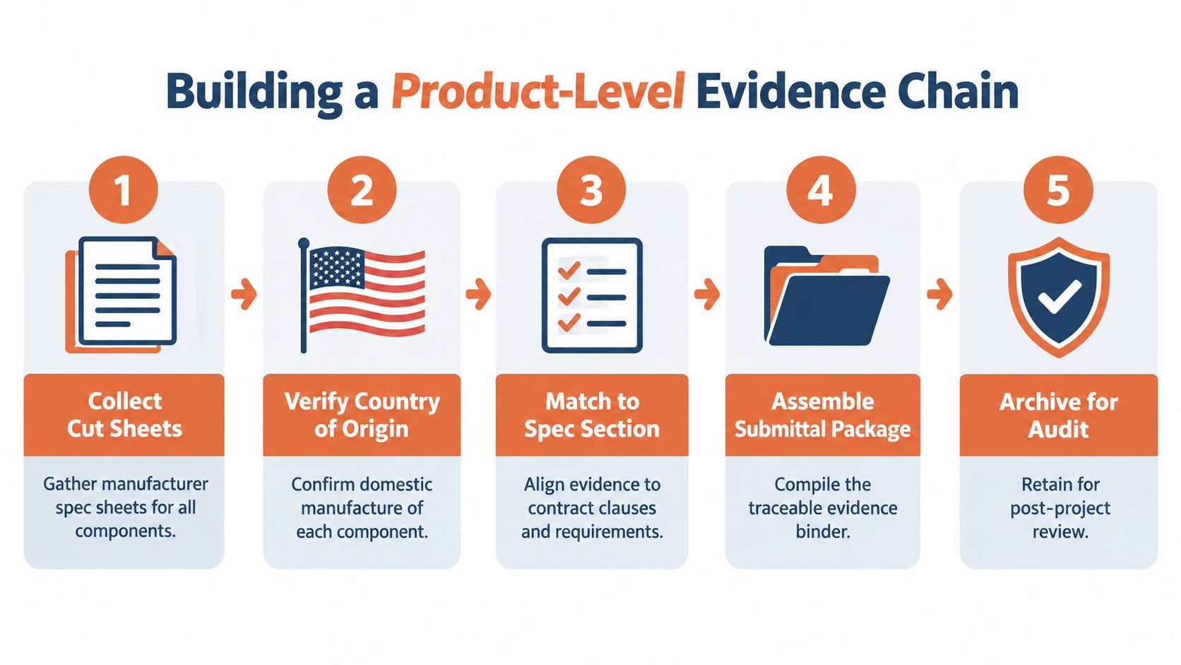
Building a Product-Level Evidence Chain
The strongest Buy American Act files are built line item by line item. If the evidence doesn’t follow the BOM, the package usually fails at the point where someone asks, “Show me how you proved this product qualified.”
Start with the item classification
The first move is to map each line item to its product category under the governing contract. A breaker, panelboard, lighting fixture, cable assembly, or steel enclosure can fall under different tests, and the wrong classification leads to the wrong documentation request. Once the category is fixed, the buyer can determine whether the item is a supply, a construction material, or part of a federally assisted infrastructure package.
Then collect the right records
Manufacturer attestations matter, but they’re not the whole file. The contractor still needs supporting records that connect the item to the submittal, the purchase order, and the applicable clause. For complex electrical assemblies, that usually means preserving cut sheets, origin statements, component-cost support when required, and any correspondence that confirms approved alternates or origin questions.
A practical sequence looks like this:
Collect cut sheets, so the technical description matches the item on the BOM.
Verify country of origin, component by component when the product is complex.
Match to the contract clause, so the submittal uses the right rule set.
Assemble the package, with traceable evidence tied to each line item.
Archive for audit, because project teams rarely control when a review happens.
Keep the burden of proof where it belongs
Federal guidance places responsibility for documenting compliance on the manufacturer signing the certification, but that doesn’t remove the contractor’s recordkeeping risk. Recipients and contractors still need records that can survive agency review, especially on switchgear, transformers, cable assemblies, lighting, controls, and EV infrastructure assembled from globally sourced parts.
If the file can’t answer who made the component, where it came from, and which clause it satisfied, it isn’t ready.
For teams that need help turning a messy BOM into a procurement-ready package, ATEK Distribution can assist with product sourcing, manufacturer coordination, approved alternatives, and compliance documentation across electrical components, including circuit protection, distribution equipment, and lighting.
Sourcing Strategies for Electrical Infrastructure
Electrical infrastructure jobs usually slip on sourcing, not on the rule itself. The part was unavailable, the substitute was never vetted, or the compliance file was treated as an afterthought instead of part of procurement.
Treat COTS items carefully
Commercially available off-the-shelf items generally receive a waiver from the domestic-content test, but that waiver has a limit. A COTS product made wholly or predominantly of iron or steel does not get the same treatment, and COTS fasteners are specifically excluded from that limitation. For enclosures, supports, hardware, and similar electrical infrastructure items, material composition can change the compliance result even when the item looks standard. COTS rule and iron/steel limitation
Before approving a standard item, a buyer should check two things: whether it is COTS, and whether iron or steel predominates. If either answer changes, the clause review may change with it, and the product may no longer fit the original submittal.
Use alternates to protect the schedule
A qualified alternate can keep the project moving when the specified product is unavailable or the paperwork is thin. The best alternates are identified before the job reaches the field, not after installation has already been delayed. That usually means screening substitutions against the bill of materials, comparing like-for-like items, and keeping the number of separate compliance packages under control.
For lighting packages, see ATEK’s guide to BAA-compliant LED products before approving substitutes. For broader electrical packages, ATEK Distribution is one example of a sourcing partner that can help with alternate screening and consolidation when the team needs to keep procurement orderly.
Source selection should make the audit file easier, not harder.
A tighter sourcing strategy gives procurement teams a cleaner submittal, fewer mismatched part numbers, and less time spent chasing missing attestations after material release.
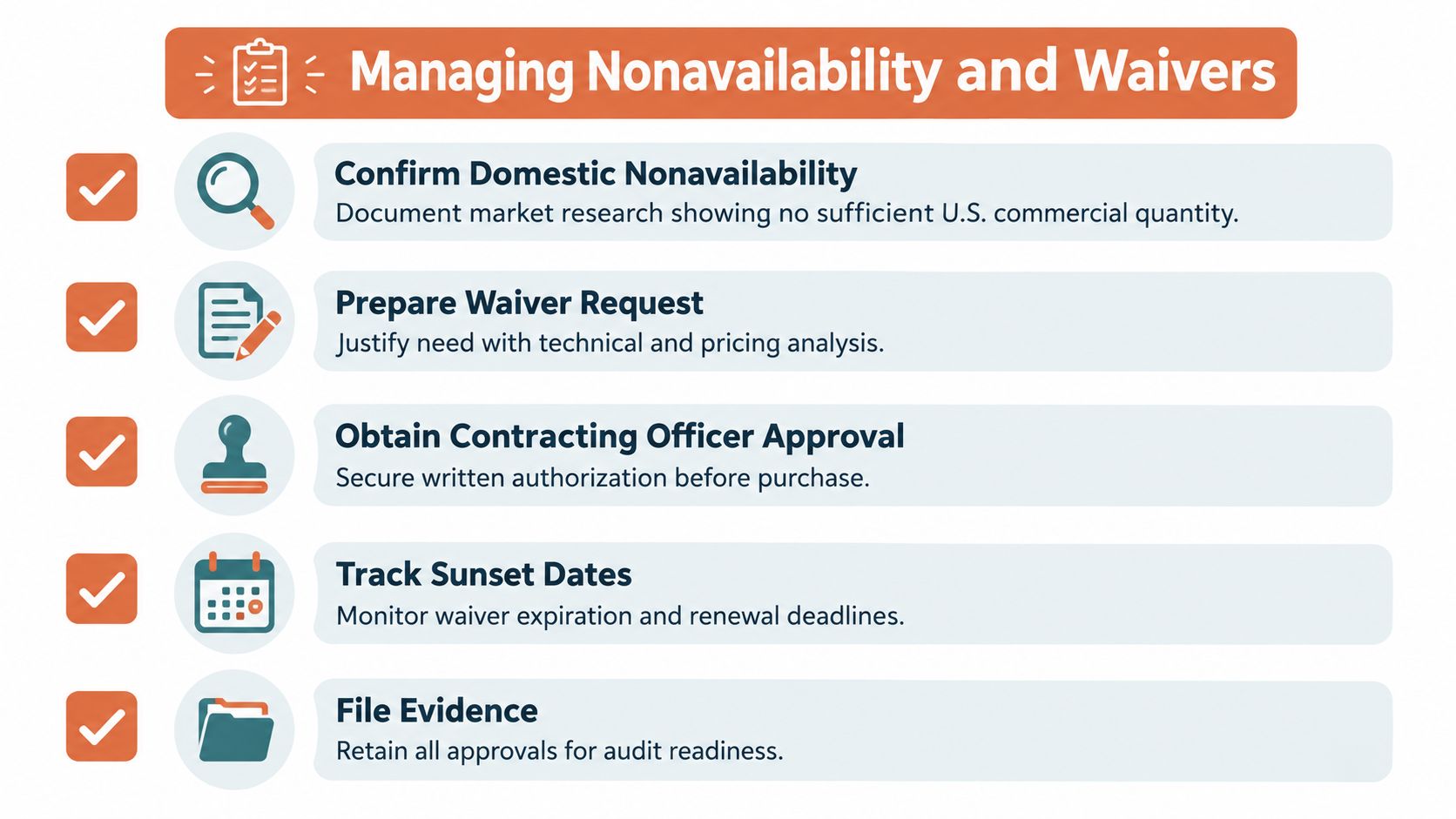
Managing Nonavailability and Waivers
A domestic part that doesn’t exist in sufficient commercial quantity is a real procurement problem, not a paperwork inconvenience. The mistake is treating nonavailability like a brand preference issue, when federal rules care about whether an acceptable domestic supply exists for the class of item being acquired.
The exception is narrow on purpose
The Buy American Act includes a nonavailability exception when products or components of the required class or kind aren’t mined, produced, or manufactured in the United States in sufficient and reasonably available commercial quantities and satisfactory quality. That means the question is broader than a preferred part number. It’s about whether a technically acceptable domestic source exists at all for the item class. Nonavailability exception guidance
For hard-to-source electrical components, the contracting officer has to apply the exception or waiver process, not just the distributor or end user. That’s important on breakers, fuses, controls, and distribution devices, where a procurement team may find plenty of substitutes but no compliant domestic source for the exact class.
How to document the problem
A defensible file usually starts with market research, then moves to technically acceptable alternates, and then to the approval path. Recent infrastructure rule changes make this even more project-specific, because older waiver assumptions can’t be reused automatically. For example, FHWA’s general waiver for manufactured products on federal-aid highway projects ended effective March 20, 2025, and FEMA maintains separate waiver paths for nonavailability and unreasonable cost, plus limited tribal exceptions on specified schedules. FHWA waiver changes and FEMA waiver paths
A practical response is to keep the waiver packet focused on facts:
Confirm domestic nonavailability with documented market research.
Compare technically acceptable alternates rather than only preferred brands.
Route the request through the contracting officer before purchase.
Track expiration dates if a waiver is time-bound.
File every approval with the submittal and PO records.
When a project team handles this early, it avoids last-minute substitutions that blow up the submittal schedule. That’s especially true on electrical work, where the wrong replacement can create coordination issues, lead-time surprises, or installer confusion in the field.
Partnering for Compliant Procurement
The fastest way to slow down a federal electrical project is to treat sourcing and compliance as separate tasks. When procurement, engineering, and submittal review happen in silos, teams spend more time fixing documentation than installing equipment.
Make compliance part of the sourcing workflow
Specialized electrical distributors can reduce that friction by screening line items early, checking product categories against the applicable clause, and identifying approved alternates before a PO is issued. That matters on mission-critical jobs, where a missing origin statement or mismatched BOM can hold up a breaker, panelboard, or lighting package at the exact moment the schedule has no slack.
For teams that need a structured source of help, Where Contractors Source Electrical Equipment is one place to evaluate how a distributor fits into the procurement process. The goal isn’t just finding inventory, it’s reducing the administrative drag that follows a noncompliant submittal.
Good procurement support shortens the path from spec to install.
A partner that can coordinate manufacturer documentation, propose acceptable alternates, and consolidate materials gives contractors a cleaner route through submittals and audit review. That’s the practical advantage on federal work, where the product has to perform and the paper has to hold up.
If your next federal project needs Buy American Act compliance support, BOM review, or help sourcing hard-to-find electrical components, contact ATEK Distribution early in the buyout process. Visit ATEK Distribution to request sourcing assistance, product documentation, or alternate evaluations before the job gets tied up in submittal delays.
An engineer asks for a 100 amp panel 3 phase and receives three competitive quotes. Each quote appears to match the request, but one is 208Y/120 V, another is 480Y/277 V, and the third has a different main-device arrangement and short-circuit current rating. The ampere value matches. The equipment does not.
That situation is common because 100 A describes only one part of the panelboard. Voltage, phase-wire configuration, usable per-phase capacity, SCCR, breaker compatibility, enclosure, and installation conditions determine whether the panel belongs in the project. Treat the nameplate as the starting line, not the completed specification.
A 100 amp three-phase panelboard is distribution equipment intended to divide a three-phase feeder into branch circuits or downstream loads. In a properly selected assembly, the panel has a bus rated for the application, a voltage and phase configuration compatible with the electrical system, listed overcurrent devices, and a marked short-circuit current rating.
The phrase 100 amp panel 3 phase identifies an equipment category, not a unique catalog item. A three-phase panel may be configured as three-phase, three-wire or three-phase, four-wire. It may use a main breaker or main lug only construction. It may be intended for an indoor industrial room, an outdoor location, or another enclosure environment. Those differences affect installation, maintenance, and approval.
UL 67 guidance requires the panelboard to be marked with its SCCR in rms symmetrical amperes. That rating addresses both the interrupting capability of the overcurrent devices and the ability of the bus structure to withstand the electromechanical forces associated with a fault. A 100 A label alone doesn't establish a 10 kA, 22 kA, or higher fault rating. The nameplate and the manufacturer's listed configuration control.
Practical rule: Never approve a quote that says only “100 A, three phase.” Require the voltage, wire configuration, main-device type, SCCR, enclosure, and breaker family.
The procurement package should also identify the bus material and rating, neutral arrangement, branch-space count, environmental enclosure rating, and whether a listed series combination is being used. Those fields determine whether the panel fits the feeder, connected equipment, available fault current, and maintenance strategy.
Common Three-Phase Configurations and Voltages
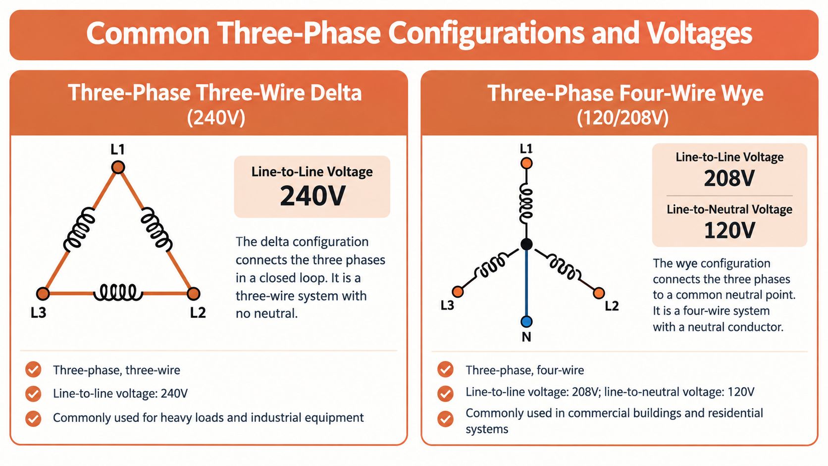
The first question is whether the facility needs a three-phase, three-wire or three-phase, four-wire panel.
A three-wire arrangement has three phase conductors and no neutral. It commonly serves line-to-line loads, including many motors and industrial machines. A four-wire arrangement adds a neutral, allowing the panel to supply line-to-neutral loads as well as line-to-line loads. The installation may also require a separate equipment grounding conductor or bonding arrangement, depending on the system and governing code.
The voltage designation matters just as much. Common configurations include:
208Y/120 V: A four-wire wye system can serve 208 V line-to-line loads and 120 V line-to-neutral loads. It suits facilities with mixed motors, controls, lighting, and receptacle loads.
480Y/277 V: This wye arrangement provides 480 V between phases and 277 V from phase to neutral. It commonly serves industrial equipment and higher-voltage lighting systems.
240 V delta: A three-phase, three-wire delta arrangement supplies line-to-line loads at the system voltage. It isn't interchangeable with a 208Y/120 V panel just because both are three phase.
The panel's 100 A rating doesn't establish any of these voltages. Confirm the facility service, transformer secondary, feeder conductors, and equipment nameplates before selecting the panel. A useful plain-language overview of phase conductors and system arrangements is AdVoltage Electrical explains three phase, but the project's drawings, equipment data, and adopted code remain the controlling references.
A buyer should also confirm whether the neutral is full-size, reduced, or omitted, and whether metering, surge protection, or other accessories require a particular interior configuration. A panel that can distribute three-phase power isn't automatically suitable for single-phase loads.
Reading the UL 67 Nameplate
The nameplate is the fastest way to separate a genuine match from a quote built around a nominal ampere rating. Read it field by field, then compare every field with the feeder study and the panel schedule.
The markings that control acceptance
Start with the voltage and phase configuration. A panel marked for 480Y/277 V isn't a substitute for one specified for 208Y/120 V. Confirm the number of wires, neutral arrangement, and grounding provisions as well.
Next, verify the bus rating and the assembly's SCCR. The SCCR must be at least equal to the calculated available fault current at the installation point. In a standard non-series-rated assembly, the panel SCCR cannot exceed the interrupting rating of the lowest-rated installed breaker or fused switch.
That lowest-rated-device rule is where many submittals fail. A bus may be physically capable of withstanding a fault, but an installed branch breaker with a lower interrupting rating can limit the listed assembly rating. A panel marked 100 A therefore doesn't prove that the complete assembly is suitable for a 10 kA, 22 kA, or higher fault environment.
What to request with the submittal
Ask the manufacturer or distributor for the listing information and the exact configuration, not a generic product family sheet. The package should identify:
Main device: Frame, poles, ampere rating, and interrupting rating.
Branch devices: Approved breaker or fused-switch family and interrupting ratings.
SCCR: Assembly rating in rms symmetrical amperes.
Enclosure: Environmental type and indoor or outdoor suitability.
Bus and neutral: Material, rating, neutral configuration, and grounding arrangement.
Series rating: Whether a listed series combination applies, including the specific upstream and downstream devices.
The UL 67 panelboard guide provides useful context for the listing and marking framework. Use it alongside the manufacturer's instructions, project specifications, fault-current study, and authority having jurisdiction review.
Main Breaker Versus Main Lug Only Construction
Two panels can share the same enclosure size and 100 A label while serving different roles in the distribution system.
A main breaker panel includes an integral main overcurrent device. It can provide local disconnecting means where the design requires one, and it may be appropriate for a service or distribution location subject to the adopted code and AHJ interpretation. The main breaker also becomes part of the interrupting and coordination review.
A main lug only panel, often called MLO, relies on the upstream feeder overcurrent device. It suits a downstream distribution panel supplied from a switchboard, transformer, or larger panel when the upstream protection and installation arrangement satisfy the design. MLO construction can avoid the cost and space associated with a redundant main breaker, but it doesn't eliminate the need to verify fault protection and disconnecting requirements.
Decision point
Main breaker
Main lug only
Primary role
Service or local distribution disconnect where permitted
Downstream distribution from an upstream protected feeder
Protection location
Integral device in the panel
Upstream device protects the feeder and panel
Review focus
Main interrupting rating, service arrangement, coordination
Upstream protection, feeder rating, accessibility, and fault current
Procurement risk
May add cost and interior space requirements
May be unsuitable where local disconnecting means are required
The upstream device must be compatible with the panel's listed configuration. That includes lug limitations, conductor material, termination requirements, and physical installation. For feeder connections and large-conductor terminations, review the available mega lugs for PVC alongside the panel manufacturer's approved connection hardware.
Calculating Usable Capacity Across Three Phases
A 100 A nameplate is only the starting point. Before a plant team signs off on a panel, the core question is how much current each phase can carry in the actual mix of motor loads, lighting, controls, welders, and neutral-connected circuits without forcing one leg past the limit first.
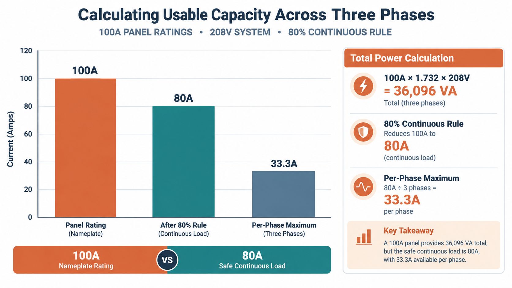
Usable capacity is set by phase balance, continuous-load treatment, feeder ampacity, voltage drop, demand, harmonic content, and the way the loads are assigned across the bus. For continuous loads, size with the NEC requirement that overcurrent devices and feeders be applied at not less than 125 percent of the continuous load, which is the same practical basis behind an 80% of the main-breaker rating operating target. On a 100 A main, that points to 80 A for the applicable loading check.
Size the panel from the highest-loaded phase. Total connected amperage is not a valid sizing basis.
A mixed-load example
Take a 208Y/120 V panel feeding a 30 A three-phase motor plus several 120 V lighting circuits. The motor current is shared across all three phases. The lighting circuits are phase-to-neutral loads, so their placement on A, B, or C matters immediately.
If those lighting circuits are distributed evenly, the panel stays reasonably balanced. If too many are landed on one phase, that leg can run close to its limit while the total connected load still looks acceptable on paper. Dividing the overall load by three misses the condition that drives panel sizing and nuisance trip risk.
The same problem shows up with a large line-to-line welder, a three-phase HVAC unit, and single-phase control power in the same panel. The welder loads two phases. The controls can sit heavily on one phase and neutral. A usable schedule has to show actual phase assignment, circuit by circuit.
What the rating does and doesn't tell you
A three-phase panel's apparent power changes with voltage and system arrangement. At 208 V, the relationship is 100 A × 1.732 × 208 V = 36,096 VA. Using the same relationship with an 80 A loading target gives a lower apparent-power figure for planning. Those numbers help with screening, but they do not replace a load calculation or a phase-by-phase review of the schedule.
For a 100 A panel, an 80 A operating target averages to about 33.3 A per phase. Treat that as a math check, not a field allowance. If one phase exceeds the design limit, rebalance the circuits, trim demand, step up feeder and panel capacity, or add a transformer if the system arrangement requires it.
Branch Breaker Selection and Coordination
Populating a panel is not a matter of filling available spaces with breakers that fit physically. The branch devices must belong to the panelboard's listed breaker family, match the bus and interior, and carry interrupting ratings suitable for the available fault current.
Check four items before approving a branch breaker:
Family compatibility: The device must be identified for use with the specific panelboard interior and bus.
Interrupting rating: Its rating must support the fault-current environment or the listed series combination.
Pole and voltage arrangement: The breaker must match the branch circuit, phase configuration, and connected load.
Coordination: Upstream and downstream devices should be reviewed for selective coordination or other project requirements.
A series-rated combination can be acceptable when the panel manufacturer has listed the specific upstream and downstream devices together for the applicable system. It isn't acceptable to combine an arbitrary low-rated branch breaker with a higher-rated main and assume the assembly inherits the main's capability. Substituting a breaker from an unlisted family can invalidate the panel's SCCR and create inspection, warranty, and safety problems.
For a practical introduction to circuit protection decisions, see this contractor guide to breaker sizing. It shouldn't replace the panel manufacturer's compatibility data or the engineer's coordination review.
Fused branches require the same discipline. Confirm fuse class, holder compatibility, interrupting rating, space, and maintenance requirements. A coordinated assembly can protect equipment more effectively than a collection of individually adequate devices, but only when the published combinations and project study support the selection. The industrial fuse selection guide can help organize the device review before the BOM is released.
Installation and Code Compliance Considerations
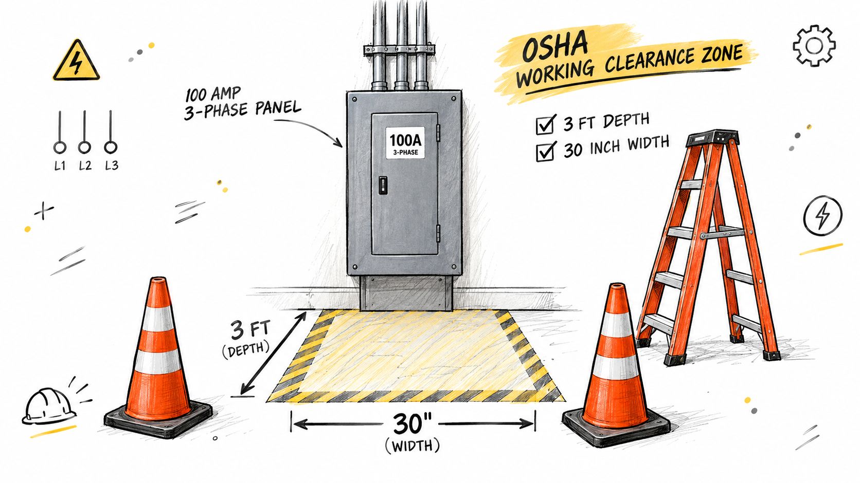
A panel that meets the submittal schedule can still fail the installation review if the physical location and supporting documentation weren't considered early. For U.S. installations, OSHA requirements for equipment rated 600 V or less generally call for 3 ft of clear working depth, a minimum width of 30 in. or the equipment width, whichever is greater, and sufficient headroom. The working area can't become storage.
The panel should remain readily accessible to qualified personnel. It should have a secure dead front and a durable circuit directory that identifies each circuit's load or destination. These details affect maintenance and safe troubleshooting, not merely the final inspection.
Documents to verify before energizing
The engineer and installing contractor should reconcile the panel with:
Feeder ampacity: Conductors, terminations, temperature ratings, raceway conditions, and voltage-drop requirements.
Overcurrent protection: Main and branch devices, interrupting ratings, and coordination.
Grounding and bonding: Equipment grounding conductor, neutral treatment, enclosure bonding, and system-specific requirements.
Neutral loading: Especially where single-phase loads or harmonics are present.
Enclosure suitability: Indoor or outdoor location, environmental exposure, and NEMA type.
Fault-current documentation: Available fault current at the panel and any required coordination or arc-flash study.
The OSHA electrical panels guidance is a useful reference for access and working-space considerations. The locally adopted electrical code, manufacturer instructions, project drawings, and AHJ decision govern the final installation. Conductor sizing and protection aren't decisions that a generic product description can make.
Typical Industrial and Commercial Applications
A 100 A three-phase panel fits many smaller distribution duties, but the right question is whether the connected equipment produces a manageable phase profile and fault environment.
Small motor control panels may use the panel to feed motor starters, drives, control transformers, and auxiliary circuits. The panel can work well where the motor schedule is modest and the feeder study supports the selected SCCR. It becomes less suitable when several motors start simultaneously or when motor starting causes unacceptable voltage drop.
HVAC equipment often combines three-phase compressors or fans with single-phase controls. A 480Y/277 V system may serve larger equipment, while a 208Y/120 V arrangement can support controls and auxiliary loads. The designer must review starting current, continuous operation, and phase assignment rather than merely adding nameplate amperes.
Light commercial distribution can include lighting, receptacles, small mechanical equipment, and tenant loads. A four-wire panel is often more flexible because it can supply both line-to-line and line-to-neutral circuits, provided the neutral and phase balance are correctly designed.
EV charging infrastructure deserves an early load review. Chargers can create sustained demand, and the facility may also carry HVAC, lighting, and process loads. A 100 A panel may serve a limited equipment group, but additional chargers or high-demand equipment can require a larger panel, load management, or a transformer.
Agricultural pumps, small process skids, controls cabinets, and mixed single- and three-phase facilities follow the same principle. A 100 A panel can be practical when the phase schedule is balanced and the fault rating is adequate. A larger panel, such as a 200 A or 400 A design, may be appropriate when the calculated demand, expansion plan, voltage drop, or motor starting profile exceeds the smaller assembly.
Sourcing and Procurement Risk in Tight Markets
When a panel goes on backorder, the alternate must preserve electrical performance, inspection acceptance, physical installation, and lifecycle support. A 100 A nameplate only starts the review. It does not confirm the right voltage configuration, usable branch arrangement, breaker family, or SCCR.
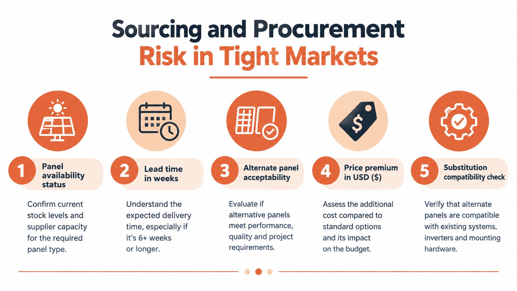
Start the alternate review before the release date slips. In tight supply conditions, substitutions get forced late, and late substitutions are where panel jobs lose time in engineering, the field, and final inspection. Eaton notes a practical five-step approach for supply-chain risk review in A five-step guide for sourcing and procurement risks in solar panel supply chains during tight markets. The same discipline applies here.
Lock these items before asking for an approved alternate:
System: Voltage, phase, three-wire or four-wire configuration, and neutral arrangement.
Construction: Main breaker or MLO, main-device frame, branch-space count, and interior layout.
Protection: SCCR, breaker family, branch interrupting ratings, and series-rating documentation.
Physical fit: Dimensions, mounting, conduit entry, bus orientation, and enclosure type.
Features: Metering, surge protection, accessory provisions, and labeling.
Compliance: Product listing, submittal documents, BAA, TAA, or government-purchasing requirements where applicable.
Purchasing mistakes get expensive here. Wrong dimensions can stop installation after the gear is already on site. An incompatible breaker family can trigger a redesign. A panel with insufficient SCCR may clear purchasing and still fail engineering review or the AHJ. A lower unit price does not offset rework, commissioning delay, or hard-to-source replacement parts later.
Current availability pressure and extended replenishment cycles are a real buying condition across many electrical categories. For a practical snapshot of pricing and supply timing, see this electrical equipment prices and lead times guide. In that environment, documentation discipline matters more. Send the distributor the full specification, not just “100 amp panel 3 phase,” so ATEK Distribution can review BOM details, coordinate with manufacturers, evaluate approved alternates, and support compliance paperwork when the original equipment is unavailable.
Quick Reference Specification Sheet
A 100 A label is only the starting line. Buyers still need the fields that determine whether the panel will fit the system, clear review, and arrive as usable gear instead of a return or redesign.
Use the following sheet in an RFQ, submittal, or internal sourcing request. Fill every field before comparing quotations.
Spec Field
Required Value
Source
Voltage
Identify the exact system, such as 208Y/120 V, 480Y/277 V, or 240 V delta
System drawings and manufacturer nameplate
Phase and wires
Three-phase, three-wire or three-phase, four-wire, with neutral requirement stated
Product application data and system design
Bus rating
100 A, with bus material and construction identified
Manufacturer submittal and UL 67 listing
SCCR
Rating at least equal to calculated available fault current
Fault-current study and listed equipment markings
Main device
Main breaker or MLO, frame, poles, rating, and interrupting capability
Panel schedule and manufacturer documentation
Branch spaces
Required number of spaces and any tandem or accessory restrictions
Panel schedule and interior layout
Breaker family
Exact listed breaker or fused-switch family
Manufacturer compatibility data
Enclosure
Indoor or outdoor suitability and NEMA type
Project location and product listing
Neutral
Included, isolated or bonded as required, with configuration stated
System design and installation requirements
Grounding
Equipment grounding and bonding arrangement identified
Locally adopted code and engineering documents
Working clearance
Access, depth, width, headroom, and no-storage confirmation
OSHA guidance and site review
Documentation
UL 67 listing, nameplate data, SCCR, device schedule, and coordination documents
Submittal package and project requirements
This sheet closes the gaps the nameplate does not. SCCR, voltage configuration, breaker family, and neutral treatment decide whether a 100 A three-phase panel can be applied on the job. Main breaker versus MLO also affects field scope, upstream protection, and available options during procurement. If the earlier nameplate section is part of your review package, use it with this table instead of relying on the ampere marking alone.
For sourcing, approved alternatives, BOM review, and submittal support on 100 A three-phase panelboards, contact ATEK Distribution with the panel schedule, system voltage, SCCR requirement, enclosure type, and delivery constraints. Attach this sheet to every RFQ so vendors quote against fields, not against the ampere number.
A contractor has just replaced a distribution panel, selected an SPD with an impressive maximum surge-current rating, and submitted the cut sheet for approval. The control panel downstream still experiences unexplained failures. That outcome is frustrating, but it isn't unusual. The largest kA number on the enclosure doesn't tell you the voltage the connected equipment will see.
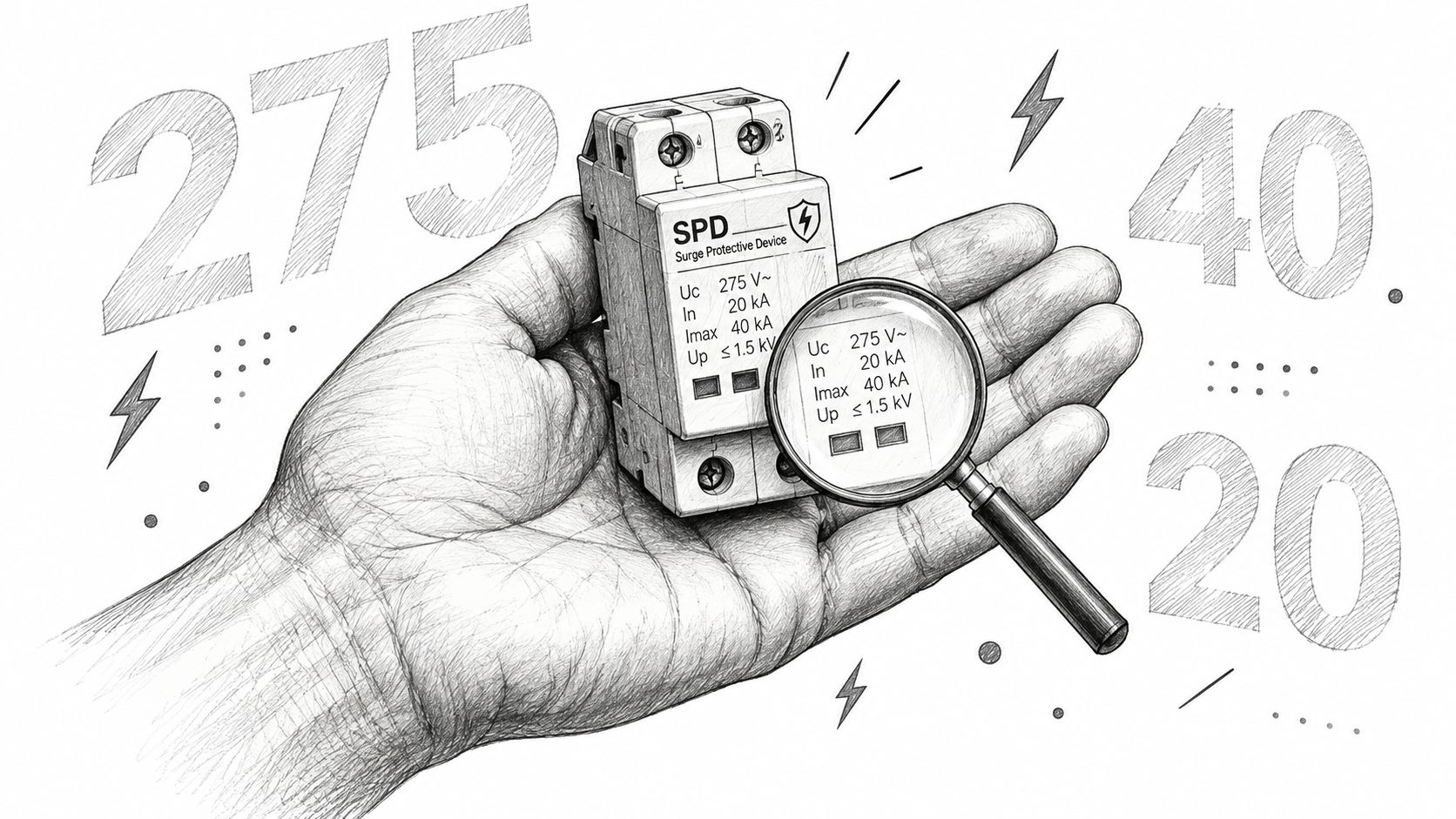
A reliable surge protection rating review starts with the complete electrical relationship: system voltage, Maximum Continuous Operating Voltage (MCOV), Voltage Protection Rating (VPR), SPD Type, protection modes, short-circuit current rating (SCCR), and installation geometry. The right device isn't necessarily the one with the biggest headline rating. It's the one that diverts the expected transient, clamps voltage within the equipment's withstand capability, and remains stable under normal system conditions.
A submittal lands on the desk with a bold kA figure at the top, yet the connected controls are still the part most likely to fail. That happens because an SPD rating block is a set of related limits and test values, not a single verdict on protection. NIST separates nominal system voltage, surge-current capability, and clamping voltage in SPD evaluation, which is the right starting point for any serious review (NIST guidance on protecting computers).
In industrial work, that distinction matters fast. Power supplies, PLC inputs, drives, networked devices, and instrument loops do not all tolerate the same let-through voltage, and the SPD with the highest surge-current headline is not automatically the better fit. I have seen acceptable current ratings paired with the wrong clamping behavior, the wrong modes, or poor lead layout. On paper the device looked strong. At the terminals, the equipment still saw too much voltage.
Read the complete rating block
Start with the electrical system and the load you are trying to keep alive. Confirm nominal voltage, phase arrangement, grounding scheme, and which conductors the SPD protects. Then read the rating block as a coordinated set of checks:
MCOV: Verify it against the system configuration and normal steady-state voltage.
VPR: Use it to judge the let-through voltage the equipment may be exposed to.
In and Imax: Use these as current-handling indicators, not as a stand-alone selection method.
SPD Type: Confirm the intended installation point under UL 1449.
SCCR: Match it to the available fault conditions at the installation.
Protection modes: Confirm the device covers the line-to-neutral, line-to-ground, neutral-to-ground, or line-to-line paths that matter in that panel.
Many reviews go off track at this point. The large kA number gets attention because it is easy to compare across cut sheets. The harder question is usually the deciding one, what voltage will pass downstream during the standardized event, and is that level acceptable for the connected equipment?
Practical rule: Use kA to screen candidates. Use VPR, MCOV, Type, SCCR, protection modes, and lead routing to decide whether the device actually fits the application.
For contractors, engineers, and facility teams, a usable submittal should let you verify those relationships without guesswork. A cut sheet dominated by one surge-current figure leaves the engineering decision incomplete. Reviewing ATEK's power and protection equipment in that context helps keep selection tied to the panel, the load, and the withstand limits of the equipment.
MCOV and System Voltage Matching
A surge protective device can look acceptable on a submittal and still be wrong for the system. I see this most often when the nominal voltage matches the panel label, but the MCOV does not match the actual voltage that appears across the protected modes. Under UL guidance, the SPD's normal operating-voltage rating and MCOV cannot be lower than the circuit's full line-to-line voltage, so selection has to follow the system configuration, not just the most familiar phase-to-neutral value (UL guidance on SPD ratings).
That distinction matters on a 480Y/277 V system. The phase-to-neutral voltage is 277 V, but the system also presents 480 V line-to-line, and the SPD has to survive the voltages seen in the modes it is designed to protect. Choosing the device from the 277 V number alone is how electrically incompatible SPDs end up in otherwise well-documented projects.
Why a low MCOV causes trouble
If MCOV is too low, the SPD can start to conduct during normal system variation instead of waiting for a transient. In a MOV-based design, that means heat, accelerated aging, and a higher chance of nuisance failure or internal disconnection long before the unit has done meaningful surge duty.
Going too far the other way also has a cost. A higher MCOV gives more steady-state voltage headroom, but it usually pushes the protection element to operate at a higher voltage as well. That reduces margin between normal operating conditions and the let-through voltage your equipment must tolerate. Manufacturers commonly advise selecting enough MCOV margin for the actual service conditions, then checking that margin against the specific product data, grounding method, voltage tolerance, and expected temporary overvoltage exposure.
The key point is practical. Apply the margin to the voltage in the protection mode you are using, not just to the nameplate system voltage.
System Voltage
Required MCOV Minimum
Protection Mode Focus
Critical Consideration
120/208 V
No lower than the circuit's full line-to-line voltage
Verify line-to-neutral, line-to-ground, and line-to-line modes as applicable
Confirm the wiring topology and each protected mode before selecting phase-to-neutral protection.
120/240 V
No lower than the circuit's full line-to-line voltage
Review split-phase line-to-neutral and line-to-line protection
Check neutral treatment and line-to-line exposure, not just the 120 V circuits.
480Y/277 V
No lower than the 480 V line-to-line condition
Confirm line-to-ground MCOV for 277 V paths and line-to-line suitability for 480 V paths
Don't select solely from the 277 V phase-to-neutral value. Evaluate line-to-ground exposure as well.
Verify more than the nominal label
Nominal system voltage is only the first screen. Grounding arrangement changes what voltage the SPD elements see, especially on systems that are solidly grounded, impedance grounded, ungrounded, or otherwise configured outside the simplest wye case. Temporary overvoltage behavior matters too.
For procurement, the submittal should show nominal system voltage, wiring topology, MCOV by protection mode, and SCCR on the same document. If a quote lists only a product family and a maximum kA number, the voltage-matching work is still unfinished, and that is where avoidable application errors start.
Voltage Protection Rating vs Surge Current
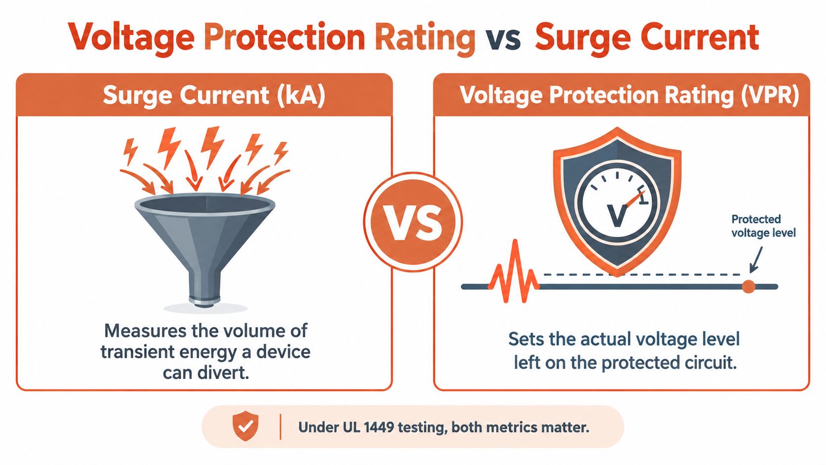
Surge-current ratings and VPR answer different questions. The current rating describes the SPD's ability to divert transient current. VPR describes the standardized limiting voltage associated with what the protected circuit may experience during the test. For downstream electronics, that voltage relationship is often the more useful first comparison.
Under ANSI/UL 1449, VPR is determined with a 6 kV, 3 kA combination-wave generator using an 8/20 microsecond current waveform. The measured limiting voltage is averaged and rounded up to an assigned value such as 330, 400, 500, 600, or 700 V (NEMA surge protection FAQs).
What VPR tells the engineer
A lower VPR generally indicates lower let-through voltage during the standardized test. That can be valuable when the protected equipment includes PLC inputs, industrial communication modules, measurement electronics, variable-speed drive controls, or other components with limited impulse withstand capability.
The comparison only works when the test context is comparable. Review VPR at the same system voltage, protection mode, installation topology, and test basis. A line-to-neutral VPR isn't interchangeable with a line-to-line value, and a favorable catalog number doesn't automatically represent the voltage at a remote load.
Published specification limits illustrate this voltage dependence. Common maximum VPR values include 700 V line-to-neutral and 1,200 V line-to-line for 120/208 or 120/240 V systems, while 480Y/277 V systems may permit up to 1,200 V line-to-neutral and 2,000 V line-to-line (Mersen surge protection information). Those values aren't a universal selection target. They show why the nominal system voltage must stay in the comparison.
The useful question isn't “Which SPD has the biggest kA rating?” It's “Which protection mode produces a compatible residual voltage at this equipment?”
Lead length changes the field result
The laboratory VPR belongs to a defined test setup. The installed result also depends on the conductors between the SPD and the equipment or bus. Connection inductance adds voltage during a fast current rise, so long, looped, or poorly bonded conductors can increase the transient voltage at the load.
That means a theoretically low-VPR SPD can underperform if the installer routes its leads through unnecessary bends or leaves excessive conductor length. Keep the connection short and direct, follow the manufacturer's routing instructions, and coordinate the bonding path with the panel construction.
Use the same discipline when evaluating related protection equipment. A technical guide to industrial fuse selection can help separate current interruption requirements from other protection decisions, but fuse ratings and SPD ratings aren't interchangeable. Each component must be matched to the fault, transient, voltage, and installation conditions it is designed to address.
Compare VPR with equipment capability
The equipment documentation should identify its impulse withstand or applicable surge withstand capability. Compare that capability with the SPD's VPR for the relevant modes, then confirm that MCOV remains high enough for continuous and temporary operating conditions.
A sound selection can therefore have a lower maximum kA rating than another product and still be the better choice for a control panel. If its VPR is appropriate, its MCOV matches the system, its UL 1449 listing applies to the intended use, and the conductors are correctly installed, it may deliver a more useful protection result at the equipment.
UL 1449 SPD Types and Applications
SPD Type tells you where the device belongs in the distribution path. It isn't a quality ranking, and a Type 1 device isn't automatically a better choice than a Type 2 or Type 3 device. The installation point, available fault current, system configuration, and coordination plan determine whether the type is appropriate.
Rockwell Automation's UL 1449 summary identifies the following nominal-discharge-current options and typical locations (Rockwell Automation UL 1449 summary):
SPD Type
Nominal discharge current options
Typical application location
Type 1
10 kA or 20 kA In
Generally connected on the line side of the service disconnect.
Type 2
3, 5, 10, or 20 kA In
Load side of the service disconnect, including distribution equipment and panelboards.
Type 3
3 kA In
Close to utilization equipment as point-of-use protection.
Type 1 for service-side placement
Type 1 devices are generally intended for connection on the line side of the service disconnect. They may be considered where the service entrance location and project requirements call for that arrangement. The device still needs the correct MCOV, VPR, protection modes, SCCR, and listing for the system.
The Type 1 label doesn't eliminate the need to review the equipment grounding and bonding arrangement. It also doesn't make a high current rating a substitute for installation coordination.
Type 2 for distribution equipment
Type 2 SPDs are used on the load side, including switchboards, panelboards, and distribution equipment. This is a common location for industrial protection because the device can be applied at the distribution point feeding control panels, automation equipment, and branch circuits.
A Type 2 device with a suitable-looking In value can still be wrong if the voltage configuration, MCOV, VPR, or SCCR doesn't match the panel. The catalog category narrows the application. It doesn't complete the selection.
Type 3 near utilization equipment
Type 3 devices are applied close to the utilization equipment. They can provide a final protection layer for sensitive loads, but they don't replace a properly selected distribution-level SPD. Their value depends on the equipment connection, lead routing, and the broader protection strategy.
For a facility with long feeders, multiple panelboards, communications wiring, or critical automation loads, the engineer should define how the layers coordinate. A Type 1, Type 2, and Type 3 arrangement is a system decision, not a reason to install every type without analyzing the paths and expected transient exposure.
The Myths Behind Higher kA Ratings
Consider two candidate SPDs for an industrial panel. One carries the bigger maximum surge-current number on the cut sheet. The other shows a lower headline kA rating, but its mode-by-mode data is clear, its MCOV fits the system, and its VPR sits closer to the protected equipment's withstand level.
For many projects, the second unit is the better specification.
That conclusion surprises buyers who have been taught to rank SPDs by the largest current number available. In practice, a higher kA rating only says the device is built to handle a larger surge event under defined test conditions. It does not, by itself, tell you what voltage the equipment will see during that event. If the VPR is higher, the protection modes do not match the system, or the MCOV is wrong for the actual service, the larger kA figure does not rescue the application.
Why “bigger” can lose
This shows up often in industrial and commercial panels where the protected load is sensitive controls, drives, automation hardware, or communications interfaces. A device with a larger surge-current rating can still be the weaker engineering choice if its let-through performance is less favorable where it matters, at the equipment terminals. I would rather defend a selection with correct system matching, credible certification data, and lower residual voltage than one built around a single brochure number.
Location also changes the outcome. Guidance from NIST surge protection guidance notes that surge behavior inside a facility is not always reduced by moving farther from the service entrance. In lightly loaded systems, assumptions about voltage dropping as you move downstream can fail. Conductor impedance, bonding, and spacing between protective devices affect coordination, so a high-rated SPD upstream does not guarantee low stress at the load.
A high-rated SPD can still fail to protect downstream equipment when the voltage configuration, coordination, bonding, or conductor routing is wrong.
The same mistake appears when engineers treat the power SPD as if it closes every surge path into the equipment. It does not. Data, communications, control, photovoltaic, and EV-charging conductors can all bring transient energy to the load through routes the power device never sees.
Good protection is coordinated by path and location. That may mean a service SPD, a distribution-level SPD, and a point-of-use device, each selected for the circuit and installed with short conductors and disciplined grounding and bonding. Oversizing one box is not a substitute for that work.
Buyers should also watch current product documentation. Requirements for SPD type, installation environment, and component classification can change, especially for outdoor, renewable-energy, infrastructure, or damp-location applications. Ask for the listing details, environmental suitability, and certification evidence that match the actual installation.
Selecting the Right SPD for Your Project
A workable SPD specification fits on a procurement checklist, but it shouldn't be reduced to one line item. Capture the electrical system, the protected equipment, the installation location, and the evidence required for approval.
Specification checklist
Nominal system and topology: State the voltage, phase arrangement, grounding configuration, and whether the device is intended for line-to-neutral, line-to-ground, neutral-to-ground, line-to-line, or other modes.
MCOV: Verify the continuous-voltage rating for every protected mode, including the full line-to-line condition where applicable.
VPR: Record VPR by protection mode and compare it with the protected equipment's impulse withstand capability.
In and Imax: Distinguish nominal discharge current from maximum surge-current capability. Don't use either value as a replacement for VPR.
SPD Type and location: Confirm whether the device is Type 1, Type 2, or Type 3 and whether that type belongs at the proposed installation point.
SCCR: Check the device's short-circuit current rating against the available fault current and the equipment assembly requirements.
Installation requirements: Identify maximum lead length, conductor routing, bonding, torque, enclosure, and environmental constraints.
Documentation: Request the UL 1449 certification evidence, product data, wiring diagram, protection modes, and environmental suitability information required by the project.
For a control panel, switchboard, or industrial load, the submittal should show these values together. This makes an approval review faster and exposes substitutions that look similar in a distributor catalog but aren't electrically equivalent.
Facilities planning a high-availability installation should also connect surge protection to the broader electrical design. A resource on how to plan a scalable data center layout is useful when equipment placement, distribution paths, maintainability, and future capacity must work together. Surge protection can't be evaluated separately from the panel locations, feeder lengths, communications paths, and critical-load architecture.
ATEK Distribution can support that review by helping contractors, engineers, and procurement teams identify surge protection devices, compare approved alternatives, assemble product submittals, and source hard-to-find components. The same project review may include circuit breakers and other distribution equipment, because SCCR, available fault current, enclosure construction, and SPD connection details often need to remain coordinated across the assembly.
A disciplined purchasing request should include the panel schedule, system voltage and topology, available fault-current information, protected equipment, installation location, required certification documents, and delivery constraints. That gives the sourcing team enough context to evaluate an alternate without changing the protection strategy.
ATEK Distribution helps contractors, engineers, facilities teams, and government buyers source SPDs and related electrical distribution equipment while reviewing technical documentation, approved alternatives, and project-specific procurement requirements. Visit ATEK Distribution to request sourcing support for your surge protection rating review, BOM, or mission-critical electrical project.
You can have the right line item on paper and still end up with the wrong transformer on site. That happens all the time with 25 kVA transformers, because the nameplate tells you capacity, but it doesn't tell you whether the unit matches the phase, voltage, cooling, enclosure, harmonics, or protection scheme your job needs.
That's the point where good specs save time. If you're sourcing for a utility feeder, a rural service drop, a light industrial load, or a commercial panel, a 25 kVA transformer is usually a small distribution transformer, not a one-size-fits-all part. For broader distribution context, ATEK's electrical distribution equipment category is a useful starting point when you're comparing the transformer against the rest of the lineup, and Bidwell's guide to win substation equipment bids is a helpful reference when the project is moving through a formal procurement cycle.
A 25 kVA transformer is a compact distribution unit for modest connected loads, but the rating alone does not make it a fit. In U.S. practice, distribution transformers are generally units with 34.5 kV or less input, 600 V or less output, and 60 Hz operation (CRS R48933). That puts 25 kVA in the low-voltage distribution layer, not in the substation or medium-power class. For a broader equipment comparison, ATEK's electrical distribution equipment category is a practical reference point.
Where the rating fits in practice
A representative 25 kVA design in that same federal efficiency research is a single-phase, liquid-immersed, naturally cooled transformer with a 14,400 V primary, 120/240 V secondary, and 60 Hz frequency. That is a common service-transformer arrangement, but it is only one valid combination. The same kVA rating also appears in other phase and voltage setups, depending on the utility interface and the downstream panel.
International procurement follows the same logic. India's Rural Electrification Corporation lists 5, 10, 16, and 25 kVA as standard single-phase transformer ratings, with voltage configurations including 11/√3 kV to 230 V and 11 kV to 230 V (REC spec PDF). That kind of standardization helps utilities and contractors stock fewer variants, manage replacements, and reduce field confusion.
Practical rule: treat the kVA as the starting point, not the selection result. Load type, voltage, phase, harmonics, enclosure, and protection decide whether the unit is actually usable.
A 25 kVA unit is usually a small distribution transformer for residential, rural, commercial, and light-industrial service. It answers the capacity question, but it does not answer compatibility on its own. Before ordering, confirm the one-line diagram, utility voltage, phase, installation environment, and procurement details that affect substitution control and compliance documentation, especially on jobs that need clear paperwork to win substation equipment bids.
Primary and Secondary Voltage, Phase, and Frequency
A 25 kVA transformer only works when the source voltage, phase arrangement, and downstream distribution line up with the system it is serving. A unit can be correctly rated and still be unusable if the primary, secondary, or frequency does not match the electrical service.
Match the transformer to the one-line diagram
The practical check starts with the one-line diagram. A single-phase unit may serve 120/240 V utilization loads, while three-phase units often feed 208Y/120 V or 480Y/277 V systems. The primary side usually lands at medium distribution voltage, and the same federal research confirms a representative 14,400 V primary design with a 120/240 V secondary.
Common 25 kVA Configurations
Phase
Primary (typical), Secondary (typical), Frequency
Single-phase
14.4 kV, 120/240 V, 60 Hz
Three-phase
Distribution primary, 208Y/120 V or 480Y/277 V, 60 Hz
Single-phase
Utility distribution primary, 120/240 V, 60 Hz
The interface has to work on both sides. If the utility supplies one primary voltage and the panelboard expects another secondary voltage, the kVA rating does not solve the mismatch. Confirm the utility service, the downstream panel voltage, and the installation drawing before the purchase order goes out. That is where substitution control starts, especially on jobs that need clean compliance paperwork and clear bid support.
Why kVA isn't the same as kW
The nameplate is stated in kVA, not kW. At unity power factor, a 25 kVA transformer can deliver about 25 kW of real power. At 0.8 power factor, it corresponds to about 20 kW. The gap matters because two loads with the same kilowatts can draw very different current, and current is what the transformer must carry.
A transformer does not care what the load is called. It cares how much current it must carry.
That is why the specifying engineer or contractor should verify whether the project is single-phase or three-phase, what the utility supplies, and what voltage the downstream panel requires. If any of those are assumed instead of checked, the risk of ordering the wrong unit rises fast.
Reading kVA, kW, Efficiency, and Losses
The nameplate capacity hides an economic question. The same federal research lists efficiencies around 98.91% to 99.07% for comparable 25 kVA configurations (CRS R48933), which still leaves roughly a kilowatt of loss in continuous service. That is the cost side of the selection, and it matters even on a small unit.
Translate capacity into usable power
A 25 kVA transformer can be electrically suitable and still be a poor fit if the load shape is wrong. A motor-heavy panel, a mixed office load, or a system with electronic drives can draw current that does not show up cleanly in connected kilowatts. Current is what heats the transformer, so the load type matters as much as the headline rating.
At unity power factor, a 25 kVA unit can deliver about 25 kW. At 0.8 power factor, it is closer to 20 kW, as noted above. That gap is why the specifying engineer should confirm the actual load profile, not just the connected nameplate sum. Two loads with the same kilowatts can impose very different thermal stress.
What the loss profile changes in the field
A 25 kVA unit operating at 99% efficiency would lose roughly 0.25 kW when fully loaded. Actual losses vary with design, temperature, voltage, and loading profile, so that figure is a reference point, not a promise. No-load loss still shows up whenever the transformer is energized, and load loss rises as current increases.
Ambient temperature and duty cycle shape the actual outcome. A transformer that sits lightly loaded most of the time behaves differently from one that runs near capacity or sees repeated starts and stops. Harmonics make the picture harder, because they can increase heating even when the arithmetic load looks acceptable.
For procurement, the practical check is simple. Confirm the efficiency class, ask for the loss profile, and match the transformer to the actual loading pattern. That is how you separate a quote that looks right from a unit that will perform the way the job needs.
Cooling Methods and Enclosure Ratings Compared
The cooling method and enclosure tell you where the transformer can live. A 25 kVA unit may be electrically correct but physically wrong if the room, weather, or maintenance environment doesn't suit it.
Choose the cooling method for the site
Dry-type units fit indoor electrical rooms because they rely on air cooling and keep liquid out of the space. Cast-resin designs seal the windings and hold up better in dusty or humid locations. Liquid-immersed units are often the better fit for outdoor or heavy continuous duty because the coolant helps manage heat more effectively.
Match enclosure rating to exposure
For enclosure selection, the environment drives the choice. NEMA 1 fits indoor dry rooms, NEMA 3R fits outdoor pole- or pad-mount service, and NEMA 4 is used where weather-tight or washdown protection is needed. The mounting style follows the same logic. Pole-mounted and pad-mounted service each bring different access, clearance, and maintenance expectations.
For outdoor selection help, ATEK's guide on how to choose electrical enclosures for outdoor use is a solid companion when you're deciding whether the transformer belongs indoors, outside, or in a more protected location.
Practical rule: if the space is dusty, wet, washdown-prone, or poorly ventilated, the enclosure discussion is not optional, it's part of the load decision.
Know when K-factor matters
Nonlinear loads such as variable-frequency drives, LED drivers, computers, and UPS systems can raise winding heating through harmonic currents. In those environments, a standard unit may be acceptable only if the harmonic burden is small. When harmonic loading is material, the transformer specification should move toward a K-rated design instead of assuming a standard unit will behave the same way.
The trade-off is simple. A standard unit may cost less up front, but the wrong cooling and enclosure combination creates a maintenance problem later. In the field, that problem usually shows up as heat, nuisance downtime, or early replacement.
Worked Sizing Scenarios for Real Loads
The quickest way to get transformer sizing wrong is to stop at connected load. A job can look safe on arithmetic alone and still fail once motor starting, demand diversity, or harmonic content gets involved.
Single motor start
A motor load can pull much more current during startup than it does in steady state. Inrush can reach roughly 8 to 12 times full-load current during the first cycles, which is enough to trip poorly chosen overcurrent devices if the selection didn't account for energization behavior (calcrig sizing guide). That's why the transformer and the protection device have to be considered together.
Mixed commercial receptacles and lighting
A building with lights and receptacles often looks easier than it is. The connected load may seem comfortably below the nameplate, but demand diversity, future tenant changes, and ambient conditions can move the result closer to the edge. A 25 kVA unit might still be the right answer, but only after the one-line, demand load, and spare capacity are checked together.
Electronic-heavy facilities
Computers, UPS systems, LED drivers, and VFD-rich facilities behave differently from plain resistive loads. Harmonic currents increase winding heating, so standard transformer selection can miss the actual thermal burden. A K-rated design may be the safer call where nonlinear loading is a genuine part of the operating profile.
A compact reference helps during review:
Motor-driven loads: start with inrush behavior, then confirm protection coordination and voltage drop.
Mixed commercial loads: check demand, future expansion, and ambient conditions before accepting the arithmetic result.
Electronic-heavy loads: verify harmonic profile and decide whether a K-rated unit is warranted.
The point is not to oversize blindly. The point is to document why the selected unit will hold up once the load starts behaving like a real facility, not a spreadsheet.
Specifications to Confirm Before Issuing a Purchase Order
A transformer PO should be based on a frozen requirements set, not a shorthand description. “25 kVA” is a capacity call, but procurement needs the full electrical and mechanical picture before the order is released.
Mandatory items
Confirm the primary voltage, secondary voltage, phase, frequency, kVA rating, impedance, and applicable efficiency requirements. Those are the items that determine whether the transformer can be energized into the intended system. If one of them is wrong, the unit can become a field change order instead of a delivered asset.
Optional but still important items
Taps, winding material, sound level, and mounting style belong in the submittal review too. They don't always change whether the unit works, but they can change maintenance access, operating noise, and replacement compatibility. For projects with alternate-product risk, that information matters more than many buyers expect.
Protection coordination and documentation
The protection package should cover primary and secondary overcurrent devices, fault current, and grounding. That's where contractor, engineer, and utility requirements have to line up. If the transformer is part of a larger build, related wire and splice details may also need to stay aligned with the upstream and downstream gear, which is where ATEK's underground wire splice kits can become part of the procurement package when the installation scope reaches beyond the transformer itself.
A clean submittal file is not paperwork for paperwork's sake. It's what keeps the field crew from discovering a mismatch after the truck arrives.
If you want a usable one-page checklist, it should read like this: electrical rating, mechanical fit, protection coordination, compliance paperwork, and installation location. Anything less invites delays later.
Typical Applications for 25 kVA Units
A 25 kVA transformer shows up in places where the load is real, but not large enough to justify a bigger distribution step. The exact fit changes by application, and the trade-offs are different in each one.
Common use cases
Small commercial buildings, often with modest lighting, receptacle, and HVAC support needs.
Agricultural service, where rural distribution and practical replacement access matter.
Light-industrial maintenance shops, especially where tools and occasional motors define the profile.
Residential developments, where repeatable standard ratings help keep replacements simple.
Telecom and traffic cabinets, where compact service equipment and stable utility interfaces are important.
Infrastructure projects, where standardization helps crews stage material and keep spares aligned.
What changes by setting
In a commercial building, ventilation and room layout often matter more than people expect. In an agricultural setting, stocked replacements and weather exposure can matter more than acoustic performance. In a maintenance shop or small industrial space, motor starting and future expansion usually dominate the conversation.
Residential and municipal projects tend to care more about interchangeability. If the utility or owner wants a repeatable spare strategy, standardized 25 kVA designs can be strategically useful because they simplify emergency sourcing and field replacement. That's especially true where failure replacement is more common than planned capacity expansion.
The practical question is always the same. Does this site need the lowest-cost nominal fit, or does it need a unit that's easier to maintain, replace, and approve later? That answer changes the application class more than the kVA number does.
Why Not All 25 kVA Units Are Interchangeable
A delayed transformer order tempts people to treat every 25 kVA unit as a direct substitute. That shortcut causes trouble because the nameplate only tells part of the story.
What has to stay fixed
A controlled substitution process should freeze the electrical requirements first. Then the buyer or engineer should identify acceptable equivalent ratings, obtain manufacturer data and drawings, verify NEC, local code, and project specifications, check BAA/TAA requirements where applicable, and confirm protection coordination before approval. That sequence is what turns an alternate into a defensible replacement instead of a guess.
What can differ even at the same kVA
Two 25 kVA units can differ in dimensions, mounting, impedance, temperature rise, sound, efficiency, taps, winding material, enclosure rating, approvals, and short-circuit withstand. That means purchase price is only one part of the risk calculation. A cheaper alternate that fails the clearance, sound, or coordination check is not really cheaper.
Practical rule: never approve a substitute until the drawings and the electrical data sheet both line up with the original specification.
Sourcing partners earn their keep in this role. A distributor can help compare alternates, request manufacturer drawings, and keep the approval trail intact. In many projects, that's the difference between an approved substitution and a stalled submittal.
Efficiency, Losses, and Service Life
A transformer that looks inexpensive on the quote can become expensive in service if the thermal profile is wrong. For 25 kVA transformers, the key decision is whether the unit will run cool enough, carry the expected load pattern, and hold up over the full life of the site.
Why losses matter on a small transformer
Even a compact unit sheds heat whenever it is energized. As covered earlier, losses are part of normal operation, and they matter more when the load is steady, the ambient temperature runs high, or the equipment sits in a confined space. In procurement terms, I treat losses as a life-cycle cost, not a line item to skim past.
Why service life changes the procurement view
The same specification document puts typical service life at 25 to 30 years, with a DOE-calculated average of 32 years (REC spec PDF). That changes the buying conversation. A slightly better choice on cooling, loading margin, or environmental fit can pay back over a long operating window, especially at a site that is likely to expand or run hard.
A transformer that is only acceptable at the moment of purchase can turn into a maintenance issue later if it lives near its limit. I push teams to review the actual load profile, not just the nameplate. Confirm the environment, the protection scheme, and the expected duty cycle before ordering. If the unit has to serve for decades, the specification should reflect the facility's future, not just the lowest quote.
Quick Reference and Selection Checklist
A clean buying checklist keeps the submittal, quote, and field verification aligned. If you're reviewing 25 kVA transformers, start with the electrical fit and only then move to the enclosure and accessories.
Selection item
Confirm
Primary voltage
Utility-side voltage and tap range
Secondary voltage
Panel or load-side voltage
Phase
Single-phase or three-phase
Frequency
60 Hz or other system frequency
kVA
25 kVA or alternate size after load review
Cooling class
Dry-type, cast-resin, or liquid-immersed
Enclosure rating
NEMA 1, NEMA 3R, NEMA 4, or site-specific
K-factor
Standard or harmonic-duty design
Protection coordination
Primary and secondary devices, fault current, grounding
Short glossary
Impedance means the transformer's opposition to fault current and voltage drop behavior.
Temperature rise is the internal heating allowance under rated loading.
Inrush is the short startup current surge during energization.
K-factor describes harmonic-duty tolerance.
No-load loss is the power the transformer burns whenever it's energized, even with little or no load.
If you can't confirm those items from the submittal, the selection isn't finished. It's only been narrowed.
If you need help sorting a transformer BOM, confirming alternates, or checking whether a 25 kVA unit fits the load, environment, and protection plan, ATEK Distribution can help with sourcing and technical review. Visit ATEK Distribution to start a quote or get support on a project-specific electrical procurement package.