A technician is standing in front of a control panel with a failed relay, a replacement in hand, and eight terminals that look familiar enough to invite a guess. That guess is where many avoidable faults begin. An eight pin relay may use the same terminal count as a compact PCB relay, but the wiring logic, socket geometry, contact arrangement, and load limits can be very different.
For panel builders, maintenance teams, OEMs, and electrical contractors, the reliable approach is straightforward: identify the relay's physical format, verify the manufacturer's pin map, match the socket to the load, and derate contacts for the actual application. The octal eight pin relay remains useful because it combines a separated coil with two independent changeover contact sets in a replaceable plug-in assembly.
Understanding the Role of the Eight Pin Relay in Control Panels
A replacement relay can fit the socket and still be wrong for the circuit. The octal eight pin relay is a panel component with a defined mechanical layout, not any relay with eight terminals. Its socket, retaining method, contact spacing, and wiring logic must match the relay body and the intended load.
In a typical control panel, the relay sits between a PLC or other low-power output and field wiring. The coil receives the control signal, while its contacts switch an interlock, alarm, valve command, or motor-control circuit. The common octal arrangement is a DPDT relay. One coil operates two electrically independent changeover poles, normally comprising two coil pins, two common pins, two normally open pins, and two normally closed pins.
That layout belongs to the plug-in octal family. Compact PCB relays may also expose eight terminals, yet place the coil and contacts in a different physical pattern and assign them according to a different wiring logic. A socket selected by terminal count alone can therefore put the wrong function on the wrong conductor. Confirm the manufacturer's pin map, relay outline, and socket keying before wiring. A breakdown of the octal relay architecture used in modular control systems provides a useful reference for this distinction.
Why the octal format remains practical
A socket keeps field conductors terminated while a technician replaces the relay. That reduces disturbance during fault-finding and makes spare replacement quicker, provided the base, clip, and relay are approved as a matching assembly.
The socket also exposes the mechanical limits that drawings can miss. Check terminal clamping, clearance, vibration resistance, and the relay's contact derating curve for the actual load. For wider panel and automation requirements, see ATEK's industrial control and automation offering. A sourcing partner can help verify the relay, socket, retaining clip, and protection accessory as one compatible family.
Internal Components and Basic Functionality
Inside an eight pin relay, the coil, magnetic circuit, armature, and contacts work as a mechanical switching system. The coil is an insulated winding around a magnetic core. When the correct control voltage is applied, current through that winding creates a magnetic field and pulls the armature toward the core.
The armature carries or operates the movable contacts. With the coil de-energized, each common terminal rests against its normally closed contact. When the coil energizes, the armature transfers the common connection to the normally open contact. The two contact poles operate from the same coil but remain electrically independent on the load side. Omega's relay reference identifies the eight pin octal relay as a DPDT device with separated coil and load contacts.
What the contact action means in practice
The labels describe the relay's state when the coil is off:
COM is the moving contact connection.
NC is connected to COM while the coil is de-energized.
NO connects to COM after the coil energizes.
That operating sequence is useful for fail-safe signaling. A fault alarm can remain connected through NC until the relay energizes, while a pump permissive or valve command can be routed through NO. The correct choice depends on what the circuit must do during loss of control power.
Mechanical action and troubleshooting
A relay can fail electrically in its coil or mechanically in its contact system. A coil may be open, shorted, or receiving the wrong voltage. Contacts may become resistive, weld closed, or fail to transfer cleanly after repeated switching of a demanding load.
Listen for the armature movement, but don't treat an audible click as proof that the load contacts are healthy. Verify coil voltage at the relay terminals, then check continuity between COM and NC with the coil off and between COM and NO with the coil energized. Always isolate hazardous power and follow the equipment manufacturer's procedure before testing exposed terminals.
Field check: A relay that clicks but doesn't pass load current often has a contact, socket, or termination problem rather than a coil problem.
Standard Octal Pinout Configurations
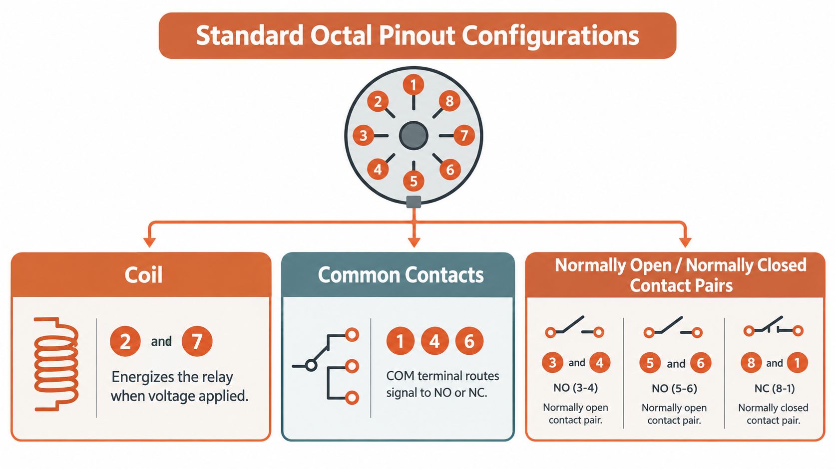
A relay can have eight terminals and still use the wrong wiring logic for an octal socket. In a standard octal layout, the coil commonly sits on pins 2 and 7, while the remaining terminals serve two changeover contacts. This standard octal wiring schematic shows pin 1 as one common, pin 4 as its NC contact, and pin 3 as its NO contact. The second pole uses pin 8 as common, pin 5 as NC, and pin 6 as NO.
Some industrial octal relays use a different contact numbering. In that arrangement, common terminals are pins 1 and 8, NC terminals are pins 3 and 6, and NO terminals are pins 4 and 5. A diagram of the alternate contact numbering used in some industrial octal relays illustrates this layout. Confirm the exact relay and socket diagram before wiring. Compact PCB relays may also have eight terminals, but their board footprint and terminal logic can differ from the round octal pattern.
A dependable identification sequence
Confirm the physical format. Check for the round plug-in body and matching octal socket. An eight-terminal square PCB relay may follow a different pin map.
Read the part documentation. Use the relay label, datasheet, socket markings, and panel drawing for the exact component family.
Locate the coil pair. Pins 2 and 7 are common in one standard octal arrangement. Verify them before applying control voltage.
Trace both poles. Identify each COM terminal and its matching NC and NO terminals. Mark conductors before replacing a failed relay.
Test both states. With power isolated, verify COM-to-NC continuity. Apply only the specified coil voltage for an energized test, then confirm transfer to NO.
Check viewing orientation. Relay underside numbering may appear reversed relative to markings beside the socket terminals.
The operating rule remains simple: coil off means COM touches NC, and coil on transfers COM to NO. Industrial relay-base guidance describes this relationship for plug-in relays used in control panels.
Relay Base and Socket Selection
The socket is part of the current path, not just a mounting accessory. A relay with suitable contact ratings can still produce a hot termination, unreliable connection, or damaged base if the socket is underspecified, poorly tightened, or mechanically unsuitable for the panel environment.
A compact PCB socket may be appropriate for a board assembly, but it isn't automatically a substitute for an industrial octal base. DIN-rail sockets typically provide a more serviceable installation, with screw terminals, relay retention, labeling space, and a replaceable plug-in interface. The mechanical choice should follow the panel layout, conductor size, vibration exposure, service requirements, and approved component family.
Compare the complete relay interface
Selection point
PCB-style socket
Industrial octal socket
Mounting
Board-mounted
Plug-in panel or DIN-rail mounting
Wiring access
Usually through PCB traces
Dedicated screw or terminal connections
Service method
Board-level replacement
Relay replacement at the socket
Mechanical concern
Board fit and pin pattern
Keyway, retention, terminal access, and conductor security
Best fit
Compact electronic assemblies
Control panels and field-serviceable equipment
Socket ratings may be independent of the relay rating. One industrial octal socket datasheet lists approvals including UL E59244 and CSA LR15734, with published configurations reaching 300 V and 15 A, or 600 V and 10 A, depending on the configuration. The socket datasheet provides the relevant approval and rating examples.
That doesn't mean every socket has those ratings. Confirm the exact base, terminal arrangement, voltage, current, conductor requirements, and mounting method. The lower-rated component governs the usable circuit.
A short demonstration can help technicians recognize the physical relationship between an octal relay and its base:
Installation rule: Match the relay, socket, retaining hardware, and any indicator or suppression module as a documented assembly. A relay that fits physically may still have the wrong pin logic or accessory compatibility.
Wiring Examples for Control Circuits
Start with the control side, not the load side. Confirm the coil voltage printed on the relay and compare it with the control circuit shown on the drawing. For a DC coil, observe polarity if the relay or its plug-in protection module includes a polarity-sensitive device. For an AC coil, follow the manufacturer's terminal instructions and the panel schematic.
A basic control sequence looks like this:
Bring the control supply through the appropriate protective and switching devices.
Connect the control return through the relay coil.
Verify that the coil receives its specified voltage only when the command is active.
Use one DPDT pole for the primary control signal and reserve the second pole for an interlock, status contact, or separate circuit when the application permits.
Keep coil conductors and load conductors identified and segregated according to the panel design.
The contact wiring depends on the desired default state. A circuit that must remain complete while the relay is off uses COM and NC. A circuit that should become complete only after energization uses COM and NO. The second pole can switch another isolated circuit, but don't assume both poles may be used interchangeably without checking the relay's contact and insulation specifications.
Resistive and inductive loads
A resistive load is generally easier for a relay contact to interrupt because it doesn't produce the same stored-energy release as a coil or motor. Inductive loads, including contactor coils, solenoids, and motors, can generate arcing when the contacts open. Use the specified suppression method, such as an appropriately selected diode, RC network, or varistor, only where it's compatible with the circuit and approved by the design requirements.
A relay contact should not be treated as a motor starter because its nominal current appears adequate. Use a contactor, overload protection, or other purpose-built switching equipment where the application requires it. The eight pin relay can command that equipment rather than carry the motor circuit directly.
For secure field terminations, see ATEK's wire termination and supplies. The right ferrule, terminal accessory, conductor preparation, and labeling practice can prevent a good relay selection from being undermined at the connection point.
Understanding Current Ratings and Derating
Many general-purpose eight pin relays are cited at 10 A for 250 VAC or 10 A for 30 VDC on resistive loads. Relay rating and derating guidance explains that this figure applies to a specified resistive-load condition and shouldn't be carried directly into motor or solenoid service.
The contact rating is not a universal permission to switch every load at that current. Contact material, voltage, inrush, interruption frequency, load power factor, ambient temperature, enclosure heat, and suppression all affect service life. Inductive loads can sustain an arc as the contacts separate, which may pit or weld the contact surfaces.
What derating changes
Derating means applying a lower usable load limit than the headline resistive rating when the actual circuit is more demanding. A relay switching a contactor coil, pump motor, or solenoid should be evaluated against the manufacturer's load category and contact-life data, not just the steady-state current shown on a nameplate.
Look for these factors in the selection review:
Load type: Resistive, inductive, motor, lamp, and electronic loads behave differently at make and break.
Inrush current: A device may draw substantially more current during energization than during steady operation.
Ambient temperature: Heat inside a crowded enclosure raises relay and socket stress.
Switching frequency: Frequent operation increases mechanical and electrical wear.
Suppression: Proper suppression can reduce contact arcing, but the device must suit the voltage and circuit type.
If the load is close to the nominal limit, select a larger switching device or use the relay to control a contactor. A fuse-selection reference from ATEK can also support the upstream protection review, but fuse protection doesn't replace correct relay derating or load classification.
Practical rule: Treat the published resistive rating as a starting point. The application decides the usable rating.
Comparing Eight Pin Relays to Other Types
An eight pin octal relay is a strong choice when the panel needs two changeover poles, a replaceable plug-in device, and a familiar round socket. It becomes less suitable when the design needs only one changeover pole, more than two poles, a compact PCB footprint, or a different terminal convention.
A five pin relay commonly serves a single changeover function with one coil and one contact pole. That can reduce wiring and physical size when a second independent circuit isn't required. The trade-off is obvious: it can't provide the same two-pole switching function as a DPDT eight pin relay.
A fourteen pin relay typically supports a higher contact count or a denser control function, depending on the product family. It may be the better fit when several isolated circuits must transfer from one command, but it also introduces a different base, terminal map, and panel footprint. An eleven pin device is another distinct format, often used where three changeover poles are required. Don't force a relay into a socket because the body appears similar. Pin geometry and numbering must match.
Requirement
Practical direction
One changeover circuit
Consider a five pin format
Two independent changeover circuits
Consider an octal eight pin DPDT relay
More contact poles
Evaluate eleven or fourteen pin families
Board-level assembly
Use the matching PCB relay and socket pattern
Field-serviceable panel
Favor a documented plug-in base system
The decision should follow the circuit count and installation method, not the terminal count alone. A compact relay with eight terminals may have a blade or PCB layout that has no relationship to the standard octal arrangement.
Procurement and Sourcing Considerations
Buying an eight pin relay by description alone creates avoidable risk. “Eight pin” identifies a terminal count, not a complete electrical specification. Procurement should capture the relay function, coil voltage and type, contact configuration, load category, contact material where specified, socket type, mounting method, approvals, and accessory requirements.
Use this verification sequence before releasing a purchase order:
Match the part family: Confirm that the relay and socket share the same mechanical keying and terminal map.
Check the load: Record whether the switched circuit is resistive, inductive, motor-related, or an interface to another control device.
Review the socket: Verify current, voltage, terminal, mounting, retention, and approval information independently from the relay.
Confirm documentation: Request datasheets, wiring diagrams, approval information, and product traceability where the project requires them.
Plan alternatives: Pre-qualify an approved substitute before a shortage turns into a panel delay.
UL and CSA markings may apply to a socket, relay, or complete assembly in different ways. Don't treat a listing on one component as automatic approval for the entire installed combination. The project engineer, authority having jurisdiction, and manufacturer documentation determine what evidence the application requires.
ATEK Distribution can support BOM review, hard-to-source relay and socket identification, manufacturer coordination, approved alternative evaluation, and compliance documentation. That type of review is particularly useful when an obsolete relay must be replaced without changing the socket layout or when a control-panel build has a long-lead component.
Technical Reference and Quick Lookup Summary
The octal eight pin relay is easiest to manage when the electrical function and mechanical interface are recorded together. The coil pins, contact assignments, socket ratings, mounting arrangement, and load category all belong on the selection record.
Reference item
Practical lookup
Common function
DPDT, with two independent changeover contact sets
Terminal count
Eight terminals
Coil arrangement in a common octal layout
Pins 2 and 7
Common contact arrangement
Often pins 1 and 8, subject to the manufacturer's map
Typical general-purpose contact rating
10 A at 250 VAC or 10 A at 30 VDC for resistive loads, when specified by the product
Socket rating
Independent of relay rating, with examples reaching 300 V, 15 A or 600 V, 10 A depending on configuration
Mounting options
Plug-in socket, panel mounting, or DIN-rail style industrial base
Default contact state
COM connects to NC with the coil off
Energized contact state
COM transfers to NO with the coil on
Use the table as a starting point, not as a substitute for the exact datasheet. Published pin assignments vary, even among products described as octal or eight pin relays. Verify the relay face marking, socket diagram, and schematic before moving conductors.
For maintenance, record the relay part number and coil rating on the panel documentation. Mark the socket terminals clearly, test the de-energized and energized contact states, and inspect for heat discoloration, loose terminations, damaged retention hardware, or contact welding. If a relay fails repeatedly, investigate the load and suppression rather than treating replacement as the complete repair.
The most reliable selection combines four checks: correct pin logic, correctly rated socket, application-specific contact derating, and documented procurement traceability. That combination prevents the common mistake of selecting a relay that fits the hole but not the circuit.
ATEK Distribution helps contractors, engineers, facilities teams, OEMs, and procurement professionals source eight pin relays, matching sockets, protective devices, and related control-panel components. For BOM review, hard-to-source parts, approved alternatives, compliance documentation, or project-specific procurement support, visit ATEK Distribution.
The crew has set a motor on its housekeeping pad, the feeder is already stubbed in, and someone needs a flexible connection between the box and the terminal enclosure. The material request says “1-inch flex,” but that shorthand leaves several decisions unresolved. Is the connection dry and indoors, or exposed to water and oil? Will the whip stay within the permitted bonding length? Can the conductors make the turn without forcing the conduit below its bend limit?
Those questions determine whether standard flexible metal conduit, liquidtight flexible metal conduit, or a larger raceway belongs on the purchase order. The trade size alone doesn't guarantee a workable installation. A fitting that doesn't match the conduit, a crowded terminal compartment, or a tight bend can turn a routine equipment connection into damaged insulation, rework, and an inspection problem.
Understanding 1-Inch Flexible Metal Conduit Applications
A typical installation uses 1-inch flexible metal conduit as the final connection to a motor, transformer, disconnect, rooftop unit, or piece of industrial machinery. Rigid raceway brings the circuit close to the equipment, then the flexible section absorbs vibration and handles the small alignment differences that occur between the equipment and the stub-up.
That role matters. A machine may shift slightly during setup, a motor may transmit continuous vibration, and an equipment pad may not line up perfectly with the conduit stub. Standard FMC gives the installer room to make that connection without forcing rigid conduit into an awkward offset. The conduit also makes future equipment service more practical, because technicians can disconnect or reposition the unit without cutting apart a rigid run.
Why the trade size is useful
A 1-inch flexible metal conduit installation occupies less space than a larger whip while still providing useful conductor capacity for equipment connections. Product references show an inside diameter near 1.00 to 1.04 inches and an outside diameter around 1.30 to 1.38 inches, depending on construction, as documented in Southwire's flexible metal conduit data.
That makes 1-inch FMC a practical middle ground. It can route through a crowded mechanical room more easily than a larger trade size, but it isn't a miniature raceway. The installer still has to coordinate hubs, fittings, enclosure entries, conductor size, bend space, and support.
Field rule: Treat a 1-inch whip as an engineered equipment connection, not as leftover flexible raceway that can be bent into whatever space remains.
Where installations go wrong
The common failure isn't always a wrong conductor count. It's often a conduit that leaves the box at an aggressive angle, runs directly into a motor connection box, or is pulled tight enough to transfer vibration into the termination. The interlocked profile can deform when installers force a sharp turn, and the resulting restriction makes conductor pulling harder and increases the chance of insulation damage.
Support also matters. FMC needs to be secured and terminated in a way that keeps its weight and movement from loading the box or equipment fitting. A long unsupported whip may function electrically while still creating a mechanical problem. If the connection needs a longer path, more protection, or a grounding arrangement beyond the permitted conditions, a different raceway strategy may be more appropriate.
Categories of Flexible Metal Raceways
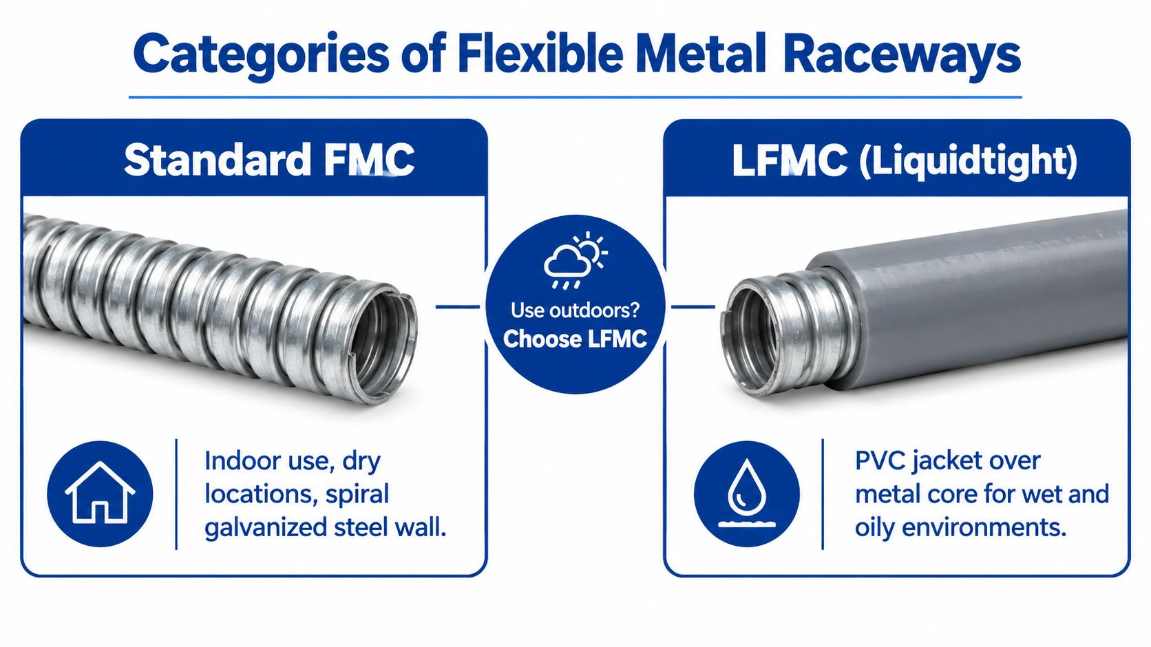
The first procurement decision is environmental. Standard FMC and LFMC may share a 1-inch trade size, but they serve different installation conditions. FMC is the interlocked metal raceway used under NEC Article 348 and governed by UL 1, while LFMC is the jacketed liquidtight product covered by NEC Article 350 and UL 360. The applicable requirements are summarized in the manufacturers' FMC and LFMC product references.
Standard FMC for dry locations
Standard FMC has a spiral interlocked metal construction without the continuous outer jacket used on liquidtight products. It's a sensible choice for dry indoor equipment connections where the raceway doesn't face washdown, standing water, outdoor exposure, or conditions that can introduce liquids into the wiring method.
It works well around indoor motors, control cabinets, dry mechanical rooms, and equipment that needs vibration isolation. It's also generally easier to inspect visually because the metal profile remains exposed. That simplicity doesn't remove the need for listed fittings, proper support, or correct bonding.
LFMC for wet and exposed equipment
LFMC adds a nonmetallic outer jacket over the metal core. The jacket helps provide a liquidtight wiring method for machinery, HVAC equipment, outdoor gear, and locations exposed to water or oil. A representative 1-inch LFMC specification lists an inner diameter of about 1.041 to 1.066 inches, an outer diameter of about 1.290 to 1.315 inches, and an 8-inch minimum bend radius, with compliance references including UL 360 and NEC Article 350 in Southwire's LFMC specification.
Ordering standard FMC for an outdoor HVAC unit is a predictable mistake. The metal conduit may be physically flexible, but it doesn't provide the same liquidtight protection. Conversely, using LFMC in every indoor connection can add cost, increase outside handling dimensions, and require fittings that don't match the standard FMC system.
For broader raceway comparisons, the distinctions discussed in this EMT versus rigid conduit guide help place flexible raceways in the larger installation plan. Choose the construction based on the environment first, then verify the fitting system, listing, and enclosure requirements.
Physical Specifications and Bend Radius Limits
A one-inch whip can fail before the pull starts. The trade size identifies the raceway category, not its exact outside profile. That difference affects knockout selection, enclosure hubs, sleeve clearance, prefab dimensions, and terminal-compartment space. Confirm the approved manufacturer's submittal before releasing fittings or cutting assemblies.
The 8-inch minimum bend radius is the smallest radius permitted by the manufacturer, not a target for forcing the raceway around an obstruction. A sharper turn can distort the interlocked armor, raise pulling friction, and restrict conductors inside the bend. The problem may remain hidden after the whip is installed.
Lay out the route before cutting. Account for the fitting body, enclosure entry, conductor exit, and the bend needed to reach the terminals. A short connection may still require more room than the centerline drawing shows, particularly where several conductors enter a crowded motor or equipment box.
That routing check often determines whether one-inch FMC is practical. If the bend cannot maintain its radius without crowding the termination, use a longer offset, change the equipment entry, or step up to a larger trade size. If water or oil exposure also governs the connection, evaluate LFMC rather than forcing standard FMC into a location it does not suit.
Coordinate the real envelope
BIM coordination should show more than the raceway centerline. Include the actual outside diameter, fitting, locknut or hub, and the clearance needed to install and tighten the connection. LFMC also requires room for its jacket and sealing components, even where its listed outside dimensions differ from standard FMC.
Prefab check: Verify outside diameter and bend radius from the selected manufacturer before building a batch of whips. A trade-size label alone is insufficient for fabrication.
Fittings and Termination Methods
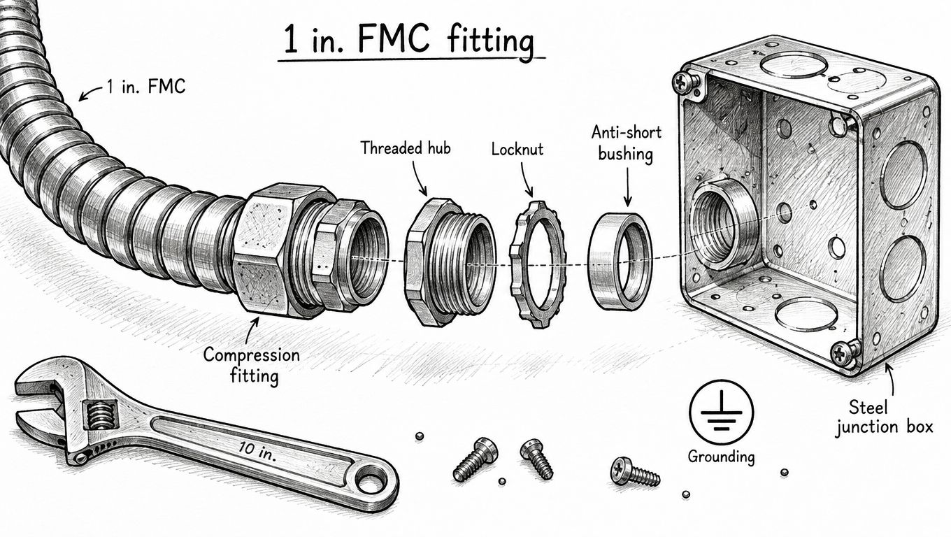
A flexible raceway performs only as well as its terminations. The fitting has to match the conduit type, enclosure entry, location rating, and bonding method. A standard FMC connector isn't a substitute for an LFMC liquidtight connector, and a fitting that grips the wrong portion of the conduit can fail the mechanical connection even when the raceway itself is listed.
For standard FMC, select a connector designed for the specific conduit construction and the enclosure entry. The connector must seat the conduit fully, engage the interlocked armor as intended, and provide a secure connection to the box or equipment. Verify the knockout or threaded opening rather than assuming every 1-inch entry uses the same physical geometry.
Choosing the termination
Set-screw-style fittings can be efficient in suitable indoor applications, particularly where the connection is accessible and the fitting is listed for the FMC construction. Compression fittings use a mechanical compression action that can provide a firm connection and are often useful where a more controlled grip is preferred. The correct choice depends on the listing, enclosure, location, and project specification, not just installer habit.
For LFMC, use a listed liquidtight fitting made for the jacketed conduit. The fitting's sealing components must engage the jacket correctly, while the internal metal core must remain bonded through the fitting system. A loose seal can admit moisture, and an improperly seated core can compromise both mechanical security and electrical continuity.
The broader selection of flexible conduit fittings includes connectors, couplings, elbows, adapters, reducers, bushings, and locknuts. Match each component to the raceway and termination rather than mixing parts from unrelated systems.
A practical installation sequence
Prepare the cut. Make a clean, square cut with the approved tool. Remove sharp metal that could damage conductors or prevent the fitting from seating.
Install the connector components. Follow the fitting manufacturer's order for locknuts, bushings, sealing rings, grounding cones, and compression parts.
Seat the conduit fully. Don't stop when the conduit merely touches the fitting. The metal core or armor must engage the connector as designed.
Tighten and inspect. Check the fitting for movement, verify the locknut or hub is secure, and perform the physical tug check required by the installation practice.
Protect the conductors. Confirm that no sharp edge, exposed armor, or displaced sealing component can contact the insulation.
A short visual demonstration can help crews understand how the fitting components stack and lock together.
The fitting should remain accessible during inspection and service. Burying a questionable termination behind equipment makes a small installation error expensive to correct.
Conduit Fill and Real-World Pullability
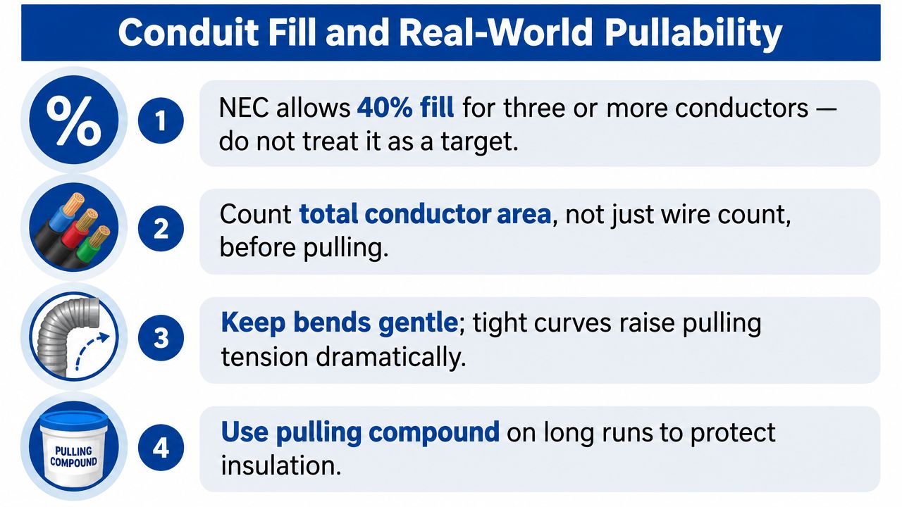
A fill table answers only one question: whether the conductor area is within the permitted raceway capacity. It doesn't tell you whether the crew can pull the conductors through a corrugated metal interior, around a tight equipment offset, and into a crowded terminal box without damaging insulation.
For 1-inch FMC, an NEC-based fill table lists capacity of 33 one 14 AWG conductors, 24 of 12 AWG, 15 of 10 AWG, and 9 of 8 AWG in the applicable table entries at Elliott Electric's conduit fill reference. Those figures are useful for code calculation, but they're not a recommendation to load every whip to the mathematical limit.
Why the table and the field disagree
FMC creates more friction than a smooth raceway because the conductors pass over an interlocked interior profile. Every bend adds resistance, and the final turn into a device box can be more difficult than the straight portion. Conductor insulation can scrape against the metal profile when the pull tension rises, especially if the installer yanks the bundle rather than controlling it.
The practical limit also depends on conductor diameter, insulation type, route length, number of bends, temperature, and access at both ends. A conductor count that looks harmless on paper may become a poor choice once the crew has to make a tight equipment connection and leave enough slack for termination.
Pull planning that saves rework
Count conductor area. Use the actual conductor dimensions from the approved wire data, not a rough assumption based only on AWG.
Plan the route before pulling. Keep the conduit as straight and gently curved as the equipment layout allows.
Protect the insulation. Use an appropriate pulling compound where the manufacturer and installation conditions allow it, and control the pull instead of exceeding the conductor's handling limits.
Separate crowded terminations from raceway sizing. A conductor bundle may fit the conduit yet fail to fit comfortably in the equipment box.
Estimator's judgment: If the crew needs excessive force to complete a 1-inch pull, the raceway is already too small for the job, even if the fill calculation passes.
Stepping up to a larger trade size can reduce pulling effort, conductor damage risk, and termination congestion. The decision should account for the full installed cost, including labor, damaged wire, replacement fittings, and the delay caused by a failed pull. For cable and conductor selection, keep the actual wire construction aligned with the raceway plan, using a supplier that can verify dimensions and compatibility through its wire and cable offerings.
Bonding and Grounding Requirements
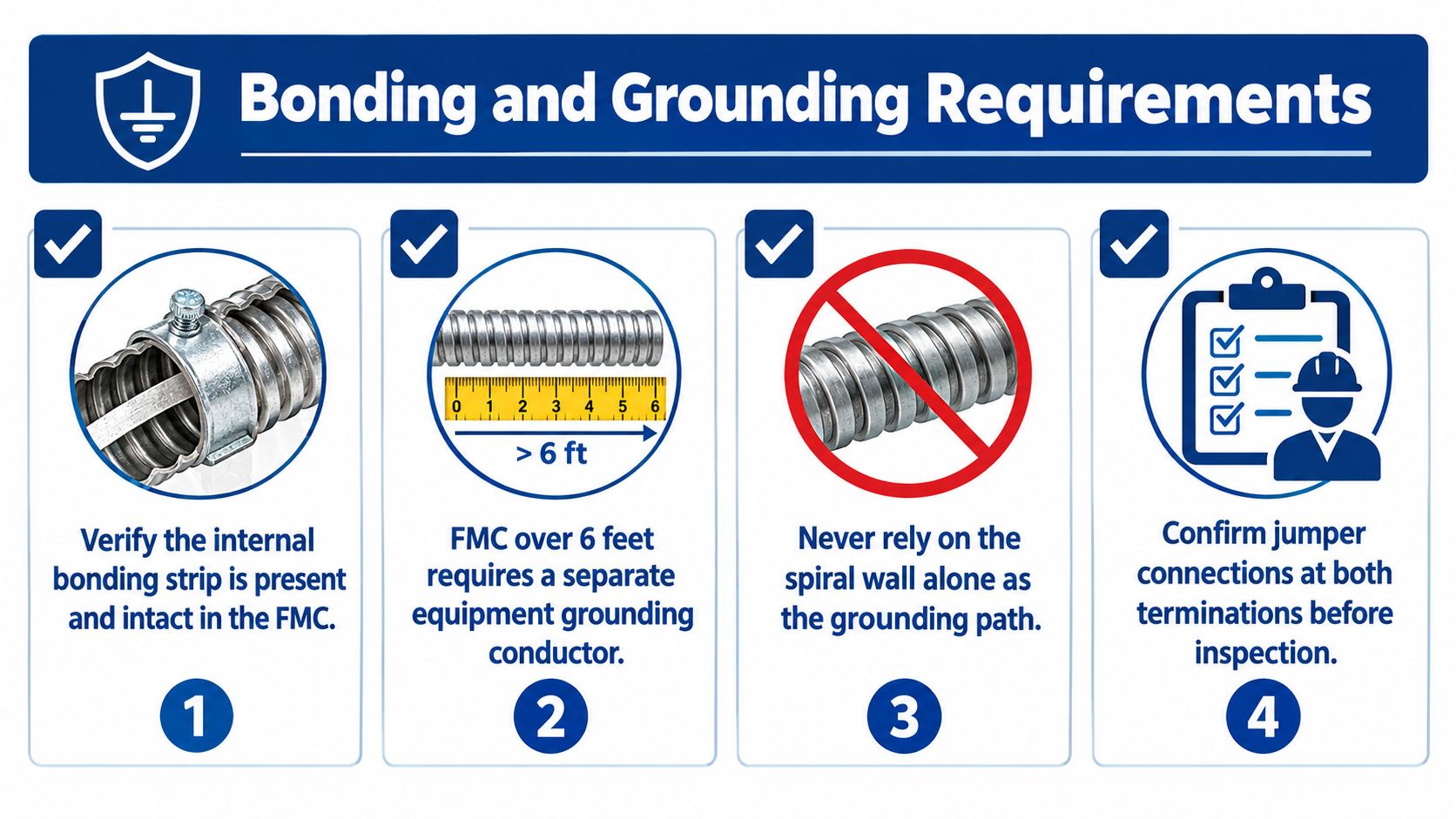
FMC can serve as a bonding path in permitted installations, but that permission has conditions. NEMA guidance identifies FMC bonding under the applicable requirements of NEC Articles 348 and 250, including a 6-foot bonding-length limit, as described in the NEMA FMC guidance document.
That limit changes the procurement question. If a 1-inch FMC connection exceeds the allowed length, the installer needs a separate equipment grounding conductor. The same decision may apply when the environment, equipment, or circuit conditions make reliance on the flexible metal wall unsuitable.
Don't confuse continuity with durability
A meter can show continuity during commissioning while the long-term grounding path remains vulnerable. Corrosion at joints can increase resistance over time, and repeated vibration can affect mechanical interfaces. Damp, outdoor, washdown, or corrosive facilities deserve a more conservative specification, particularly where maintenance access is poor.
A separate equipment grounding conductor gives the fault-current path an independent route through the flexible connection. It doesn't eliminate the need to bond the raceway correctly, but it reduces dependence on the interlocked metal profile and its terminations.
Check both ends
Inspectors and commissioning teams should be able to verify the bonding path at the box and at the equipment. Confirm that the fitting is listed for the raceway, that the connection is mechanically secure, and that any required bonding jumper or internal grounding conductor is continuous between terminations.
Use a dedicated grounding conductor when the connection length, installation environment, equipment design, or governing electrical requirements call for it. Don't make the field electrician infer that requirement from a vague material description such as “1-inch flex.” Put the raceway type, fitting type, length, and grounding method on the submittal or material schedule.
Cross-References to Related Raceways
1-inch FMC solves a specific problem. It provides a flexible, metal connection between fixed infrastructure and equipment that moves, vibrates, settles, or needs service access. It isn't automatically the right replacement for EMT or rigid metal conduit on a long exposed run.
Decision matrix for common choices
Raceway
Best use
Strength
Limitation
1-inch FMC
Final equipment connections in suitable locations
Handles vibration and alignment changes
Limited by bend radius, support, bonding conditions, and pullability
EMT
Long, straight indoor runs
Efficient for organized routing and broad infrastructure paths
Doesn't accommodate equipment movement or terminal misalignment well
RMC
Areas requiring stronger physical protection
Robust protection for severe exposure
Heavier, slower to install, and less practical for routine flexible connections
EMT usually earns its place on straight ceiling routes, wall runs, and organized distribution paths. It provides a clean, rigid pathway, but it becomes awkward at motor terminals and vibrating equipment. Trying to force EMT into the last connection often produces offsets that consume space and make service more difficult.
RMC belongs where physical damage is a serious concern or where the project specification requires a heavy-duty metallic raceway. Its strength is valuable in exposed industrial areas, loading zones, and other locations where a lighter raceway may not provide enough protection. Its weight and installation effort make it a poor default for every equipment whip.
Build a hybrid system
Many good installations use more than one raceway type. EMT carries the fixed run, a box or disconnect provides the transition, and FMC or LFMC handles the final equipment connection. That arrangement puts each wiring method where it performs best instead of making one product solve every condition.
For outdoor equipment, the flexible portion needs the environmental protection of LFMC and fittings designed for that product. For dry indoor machinery, standard FMC may be adequate, provided the bend, support, termination, fill, and bonding requirements are satisfied.
The right question isn't “Which raceway is cheapest per foot?” It's “Which combination gives the crew a secure, serviceable, inspectable path with the fewest avoidable transitions?” Material price matters, but so do fitting labor, pulling time, equipment access, and the cost of reopening a completed connection.
Quick Reference and Procurement Checklist
When a purchase request says 1-inch flexible metal conduit, stop and clarify the installation before releasing material. A complete order identifies the raceway, environment, fittings, grounding method, and conductor plan.
Confirm the raceway
Choose the construction: Specify standard FMC for the intended dry-location application, or LFMC where the wiring method must resist liquid exposure.
Verify the listing: Match standard FMC to the applicable UL and NEC requirements, and confirm LFMC documentation includes its required liquidtight listing.
Check the dimensions: Use the manufacturer's inner and outer diameters for enclosure entries, hubs, sleeves, and BIM coordination.
Record the bend requirement: Preserve the manufacturer's minimum bend radius in the layout and prefab drawing.
Confirm the fittings
Match the connector: Use fittings listed for the exact FMC or LFMC construction.
Coordinate the entry: Verify knockout, hub, locknut, bushing, and enclosure compatibility before shipment.
Specify the sealing parts: LFMC installations need the fitting components that maintain the liquidtight rating.
Plan service access: Don't place a termination where the crew can't inspect or retighten it.
Confirm the conductors and bonding
Calculate actual fill: Use conductor area and the applicable fill table. Don't treat the listed maximum as the preferred field load.
Review the pull route: Account for bends, friction, conductor insulation, and terminal-box space.
Check the length: Determine whether the FMC connection stays within the permitted bonding conditions.
Add the grounding conductor when required: Include it in the material list rather than expecting the installer to improvise in the field.
A strong submittal should show the manufacturer, product family, trade size, listing, dimensions, bend radius, fitting series, environmental rating, and grounding arrangement. That level of detail prevents the warehouse from sending standard FMC when the crew needs LFMC, or sending a conduit that fits the label but not the equipment entry.
For project teams, the most reliable workflow is to confirm the route and termination first, then select the raceway and conductor package. That sequence avoids the common trap of choosing 1-inch flex because it appears on the plan, only to discover that the actual equipment connection needs more room or a different environmental rating.
ATEK Distribution can help contractors and project teams source 1-inch FMC, LFMC, compatible fittings, wire, and related raceway materials while reviewing specifications and compliance documentation. Visit ATEK Distribution to submit your requirements and coordinate sourcing for equipment connections that need the right product, fitting, and grounding approach.
A crew finishes pulling tray cable wire through an industrial cable tray and routes it toward a motor starter. The cable is supported neatly, the terminations look clean, and the material matches the approved conductor size. At rough inspection, the installation still receives a correction because the cable leaves the tray and continues exposed to the equipment without the required exposed-run rating.
That failure rarely comes from bad workmanship. It usually starts earlier, when a purchasing description says “tray cable” without distinguishing standard Type TC from Type TC-ER. The difference affects routing, support, physical protection, environmental suitability, submittal approval, and the labor needed to complete the transition into equipment.
A motor feeder can pass through an industrial tray correctly and still fail inspection at the equipment approach. The common mistake is ordering standard Type TC, then routing it from the tray to a motor, panel, or junction box as an exposed cable. Straps may be installed neatly, but the product marking may not permit that portion of the route. The inspector then treats the installation as an unapproved wiring method.
The correction costs more than conduit and fittings. A crew may need to return, install a short raceway, replace fittings, add supports, and reschedule inspection. On a congested project, that can consume a shift of electrician time and delay energization while the equipment and other trades wait for the revised connection.
Field rule: Never approve a tray cable purchase from the words “tray cable” alone. Confirm the exact listing and the complete route from the tray to the equipment.
Tray cable wire is a factory-assembled product class, not a generic name for any cable installed in a tray. NEC Article 336 defines Type TC as a factory assembly of two or more insulated conductors, with or without associated grounding conductors, under a nonmetallic jacket. The article addresses its installation and permitted uses, while UL 1277 governs the product standard. Review the NEC Article 336 definition and installation overview before accepting a substitution.
That construction distinguishes tray cable from individual building wire. Building wire can be suitable inside a raceway, but it does not automatically provide the factory assembly, jacket, flame performance, or listing required for a Type TC application. A Type TC listing also does not authorize every exposed transition, unsupported drop, or outdoor route.
Why the route matters more than the label
Trace the route physically. Mark the tray section, transition point, equipment approach, and each location where the cable becomes exposed. The rating must suit the complete path, not just the segment inside the tray. Put those points on the drawing and submittal so procurement, installation, and inspection use the same description.
The engineer identifies the wiring method, procurement verifies the cable marking, and the installer follows the approved route. If those descriptions differ, the inspector must resolve an ambiguity that should have been settled before delivery.
The practical distinction is direct. Standard TC belongs within the conditions allowed for Type TC. TC-ER is intended to support an exposed run when the applicable NEC conditions are satisfied. Neither designation removes the need for proper support, bend control, environmental protection, ampacity calculations, and AHJ acceptance. A small difference in the purchase description can therefore create a field correction, lost labor, and a delayed inspection.
Anatomy and Flame Performance of UL 1277 Cable
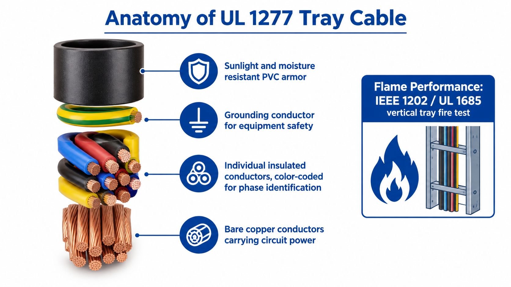
UL 1277 tray cable starts with multiple insulated conductors assembled under a nonmetallic jacket. The jacket protects the assembly from the mechanical and environmental stresses associated with cable trays, raceways, and supported outdoor locations. The conductors may be copper, aluminum, or copper-clad aluminum, depending on the listed construction and project specification, as described in the UL 1277 standard scope.
What the jacket and conductors do
The insulated conductors carry the circuit power or control signals. The grounding conductor, where included, provides the equipment grounding path specified by the design. Fillers and assembly components help create a stable, round cable profile, while the outer jacket holds the conductors together and provides the listed environmental and mechanical characteristics.
The minimum conductor size permitted under the UL 1277 definition is 18 AWG, according to published UL 1277 technical guidance. That minimum doesn't mean every small conductor is appropriate for every tray installation. Ampacity, terminal ratings, voltage drop, short-circuit withstand, control function, and the exact cable listing still govern selection.
Modern UL 1277 requirements also support dual-rated 600V/1kV tray cable. Manufacturers can qualify products for the higher voltage class when they use recognized 1 kV conductors and pass the required AC hipot test. A dual rating can simplify a project's approved-material schedule, but it shouldn't be treated as a universal replacement for a cable with a different environmental, flame, or exposed-run listing.
Why flame testing matters in a crowded tray
Cable trays often carry multiple circuits in close proximity. If a fault or external ignition exposes a cable assembly to sustained flame, a weak jacket can allow fire to travel along the pathway and affect neighboring circuits. UL 1277-listed tray cable must pass the UL 1685 vertical flame test, commonly referenced with IEEE 1202 and FT4 performance.
The test uses a 70,000 BTU/hr ribbon burner in a vertical chamber for 20 minutes, as summarized in technical guidance on identifying tray cables. Passing that test doesn't make a cable fireproof. It demonstrates that the construction has been evaluated for limiting flame propagation under a recognized tray-cable test method.
Use the listing as an engineering control, not as a substitute for installation discipline. Tray fill, spacing, support, separation, and the surrounding fire protection strategy still matter. A cable that passes the flame test can't compensate for an overloaded tray or an installation that ignores the manufacturer's instructions.
A product demonstration can help crews visualize the construction and handling requirements. Review the technical material before approving a substitute, and use the wire and cable product range when comparing available constructions.
Standard TC Versus TC-ER Exposed Run Ratings
The key question isn't whether both products can be installed in a cable tray. The question is what happens after the cable leaves the tray.
Standard Type TC is selected for permitted tray, raceway, or supported outdoor conditions. A TC-ER designation adds an exposed-run allowance between the tray and connected equipment, provided the installation satisfies the applicable Article 336 conditions. That can remove a short conduit transition, but it doesn't create permission to leave the cable unsupported or expose it to conditions outside the listing.
Feature
Standard Type TC
Type TC-ER (Exposed Run)
Primary route
Cable tray, raceway, or permitted supported outdoor location
Cable tray plus permitted exposed run to equipment
Equipment approach
Usually requires a compliant raceway or other approved protection when leaving the tray
May allow the listed cable to continue exposed under the applicable conditions
Support
Must follow the cable and installation requirements
Must be secured and supported for the exposed segment
Physical damage
Requires protection where the route is vulnerable
The exposed allowance doesn't remove physical-damage limitations
Environmental exposure
Must match the product listing
Must match sunlight, moisture, temperature, chemical, and location requirements
Procurement check
Verify Type TC and voltage, conductor, jacket, and flame listings
Verify Type TC-ER marking plus all route-specific requirements
Where TC-ER earns its place
TC-ER can make sense when a tray runs directly toward a motor, control enclosure, or other equipment and the final approach is visible, accessible, and adequately protected. Eliminating a short conduit section may reduce fittings, field measurements, threading or bending work, and installation steps. The benefit is strongest when the equipment layout is stable and the cable can be supported without sharp offsets or tight bends.
The labor advantage disappears when the route still needs conduit for physical protection. It also disappears when the product's sunlight or moisture resistance doesn't match the location, when the cable exceeds its bending limits, or when the crew has to add supports and corrections after inspection.
Practical distinction: TC-ER can simplify a transition. It cannot simplify an unclear design.
When standard TC is the safer choice
Use standard TC with a compliant raceway or protected transition when the cable passes through a location exposed to impact, abrasion, vehicle traffic, sharp edges, or difficult maintenance activity. A full conduit pathway may also be preferable where the AHJ expects a protected equipment approach or where the cable manufacturer's instructions limit exposed installation.
Procurement should put the route description beside the cable description. “Three-conductor tray cable” is incomplete. The purchase specification should identify the voltage class, conductor construction, jacket requirements, flame listing, environmental exposure, and whether the exposed-run segment requires TC-ER.
Navigating NEC Article 336 and Tray Fill Limits
A tray route can pass an initial design review and still fail at inspection when the cable listing, tray capacity, and exposed sections do not match. Article 336 addresses Type TC wiring methods and their permitted uses. Article 392 addresses the tray system. These requirements work together, but approval of the cable does not establish approval of the complete pathway.
Begin with the installed tray conditions. Calculate usable tray area from the cable outside diameters, circuit arrangement, tray type, support spacing, and manufacturer instructions. Check tray fill separately from ampacity adjustment. A cable arrangement can fit physically while requiring a different ampacity calculation, or satisfy ampacity requirements while exceeding the tray's usable capacity.
Keep the cable and the tray approvals separate
Three-or-more-conductor cables may be listed for exposed runs under the conditions in NEC Article 336.10(7), but that allowance depends on the actual cable listing and installation. Confirm the wording on the cable and project submittal rather than applying the allowance to every product described as tray cable.
The tray requires its own review under Article 392. Treat usable space as the manufacturer and design documents define it, not as the full nominal opening. Power, control, grounding, and mixed-voltage circuits may require different arrangements or separation. The cable's actual outside diameter also matters more than a generic product-family name.
A tray-specific field review should include:
Measure actual cable outside diameter: Compare it with the tray's usable width and cross-sectional area rather than counting conductors.
Check the fill calculation: Use the selected cable construction and the proposed circuit arrangement, including any planned additions.
Review ampacity separately: Apply the adjustment requirements for the installed grouping and tray configuration.
Verify support spacing: Confirm that the tray and any cable supports suit the cable weight, installation method, and manufacturer instructions.
Confirm vertical sections: Check that drops and risers provide the support required by the cable construction and installation details.
Document substitutions: Require design review before accepting a different jacket, outside diameter, conductor size, or listing.
Detail the tray-to-equipment connection
A tray calculation does not resolve the final connection. The transition drawing should show the cable's exit point, support method, bend radius, cabinet entry, and the point where additional physical protection begins. Those details affect labor as well as compliance. A standard TC cable may need conduit or other protection at the equipment approach, while a correctly listed TC-ER product may permit a more direct exposed connection where the installation conditions allow it.
The 18 AWG minimum conductor size associated with the UL 1277 definition describes product scope, not a design shortcut. A smaller conductor may fall outside the intended Type TC listing. A larger conductor can still create problems if its outside diameter exceeds the tray calculation or its terminations do not accept the selected construction.
Use cable management equipment and support products when configuring the tray pathway, and match each support method to the cable listing and approved details. The procurement package should show the tray calculation, cable identification, and transition requirements together, so an apparently minor substitution does not create hidden field labor or an inspection failure.
Matching Cable Construction to Industrial Environments
A cable that works inside a controlled manufacturing space may fail quickly on a rooftop or in a wastewater area. Voltage and conductor count are only the starting points. The jacket and insulation system must match sunlight, moisture, oil, chemicals, temperature cycling, movement, abrasion, and the physical access around the tray.
Match the environment before the catalog number
In a climate-controlled plant, the primary concerns may be cable routing, tray organization, ampacity, termination, and maintenance access. That doesn't eliminate the need to verify the jacket rating, but the environment may be less aggressive than an outdoor installation.
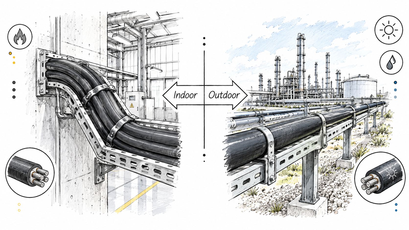
Rooftop solar arrays bring direct sunlight, temperature cycling, wind movement, and weather exposure. A tray cable selected for that route should carry the appropriate sunlight and moisture characteristics, and the supporting tray system must keep the cable from rubbing against sharp edges or moving under wind loads. A cable listed for an indoor dry location shouldn't be treated as an outdoor substitute.
Wastewater facilities can expose the jacket to persistent moisture, cleaning chemicals, corrosive atmospheres, and maintenance traffic. Petrochemical racks add another layer of concern, including oil exposure, heat, hazardous-location requirements, and the need to protect cable from impact during plant work.
A practical environment review asks:
Sunlight: Is the jacket marked or documented for the intended outdoor exposure?
Moisture: Is the wet-location performance appropriate for the route and drainage conditions?
Chemicals and oil: Does the jacket resist the substances present at the facility?
Temperature: Will the cable remain flexible and stable through the site's operating and installation temperatures?
Physical stress: Could workers, vehicles, tools, vibration, or wind damage the exposed portion?
Maintenance access: Can technicians reach the cable without creating repeated abrasion or unsupported movement?
Mixed tray and conduit paths need one continuous specification
A cable may pass through several environments on the same circuit. For example, a route can begin in an indoor tray, cross an outdoor rack, enter a conduit, and finish at a motor enclosure. The specification must address the most demanding section and any transition-specific requirements.
Standard TC and TC-ER decisions intersect with construction. An exposed-run rating may solve the routing issue, but it won't correct an unsuitable jacket compound or make a cable resistant to a chemical it wasn't designed to tolerate. Likewise, a sunlight-resistant cable still needs proper support and protection from physical damage.
Ask the manufacturer for the complete data sheet, not just a short catalog line. Confirm the listing, jacket material, wet and dry ratings, sunlight status, oil or chemical resistance, bending guidance, and approved installation methods before the submittal reaches the field.
Procurement Verification and Submittal Best Practices
The reel should be inspected before it reaches the installation crew. A correct purchase order can still result in a wrong shipment, a substituted construction, damaged jacket, or missing exposed-run designation. Receiving personnel need a verification process that compares the delivered cable with the approved submittal.
Verify the jacket marking first
Read the printing along the cable. Confirm the product type, voltage rating, conductor count, conductor size, grounding configuration, and any required TC-ER designation. The marking should support the exact route shown on the drawings. Don't rely on a distributor description that shortens the manufacturer's full marking.
Check the UL listing and product standard against the submitted cut sheet. If the project requires a dual-rated 600V/1kV product, the jacket and documentation should show that rating. If the project requires an exposed run, the marking must support that use rather than merely identify the product as generic Type TC.
Use a receiving checklist that creates evidence
A short receiving inspection protects the project when a substitution or damage claim arises. Record the result against the reel or shipment, not only against the purchase order.
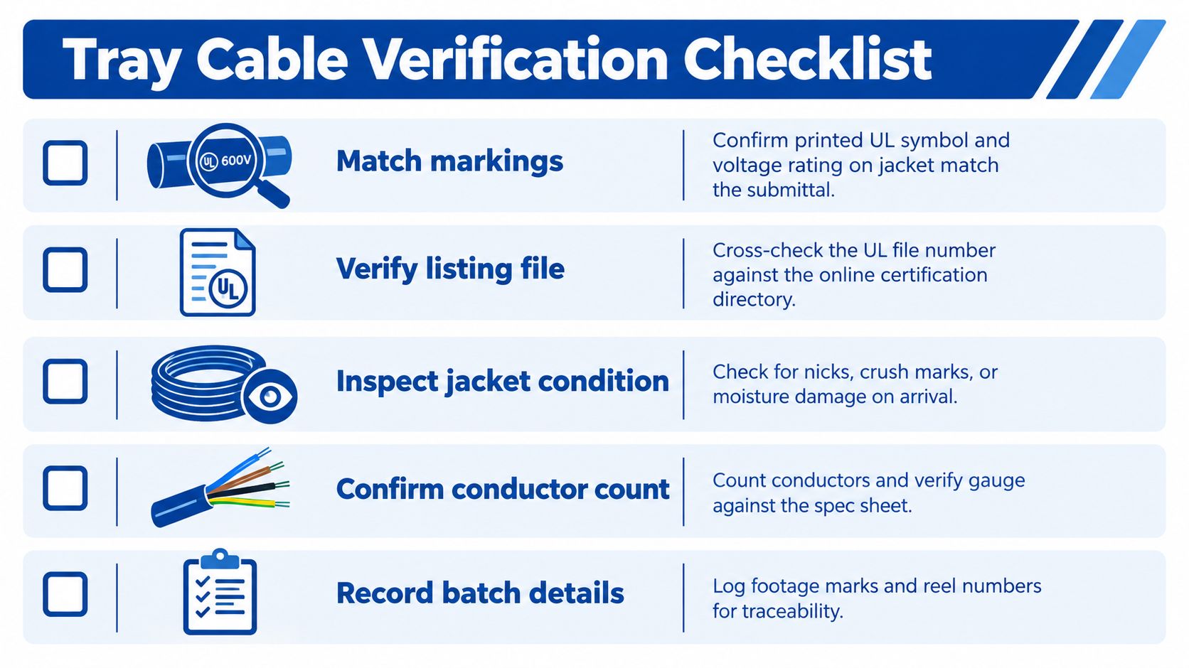
Match the markings: Compare the printed jacket information with the approved submittal and equipment schedule.
Verify the listing: Confirm the applicable UL 1277 listing and any required TC-ER designation in the manufacturer documentation.
Inspect the jacket: Look for nicks, crushing, abrasion, flattened sections, moisture damage, and exposed conductors.
Confirm conductors: Check the conductor count, gauge, insulation identification, grounding conductor, and shielding configuration where applicable.
Record reel details: Capture footage marks, reel identification, manufacturer part number, and delivery documentation.
The UL certification directory can support listing verification when the project requires confirmation beyond the printed jacket. Use the manufacturer's current data sheet for construction and application details, then retain the approved version with the project records.
Control substitutions before they become field work
A substitute can look equivalent on voltage and conductor size while differing on jacket compound, wet rating, sunlight resistance, bend requirements, or exposed-run authorization. Require a written technical comparison before accepting an alternate. Government and institutional projects may also require Buy American Act or Trade Agreements Act documentation, so procurement should collect compliance records before shipment rather than during commissioning.
ATEK Distribution supports contractors sourcing electrical equipment with product sourcing, submittal documentation, alternate evaluations, and procurement coordination. Treat that support as part of the verification process, not as a replacement for the engineer's approval or the AHJ's interpretation.
Cable selection and cable availability are connected, but they aren't the same decision. A project may need a particular conductor arrangement, jacket construction, voltage class, flame listing, and TC-ER designation, while the supplier offers only a visually similar product. Ordering the nearest catalog match creates risk if the marking or installation scope differs.
A specialized procurement partner can help the project team compare manufacturers, identify acceptable alternates, gather submittals, consolidate material, and coordinate delivery. That matters when the cable must arrive with the correct documentation and when a late substitution would force an engineering review or inspection correction.
The sourcing process should begin with the route, not the part number. Give the supplier the tray layout, exposed transitions, environmental conditions, conductor requirements, voltage class, termination details, and documentation requirements. Ask for a line-by-line comparison when the proposed product changes the Type TC or TC-ER designation.
ATEK Distribution supplies wire, cable, cable tray, fittings, and related infrastructure products, and provides sourcing, technical specification review, alternate product evaluation, compliance documentation, material consolidation, and expedited procurement support. For a mission-critical installation, that combination helps the project team keep the approved cable, the installation route, and the receiving records aligned.
Before ordering, send ATEK Distribution your tray route, conductor schedule, environmental requirements, and required TC or TC-ER designation for a technical sourcing review. Visit ATEK Distribution to request product options, submittal support, and coordinated procurement for tray cable wire and related cable-management infrastructure.
A contractor opens a panel during a remodel and finds two adjacent single-pole breakers sharing a neutral. The handles appear connected, but the inspection question is immediate: is this a listed breaker handle tie, or a field-made substitute, and does it provide the protection this circuit requires? That distinction affects maintenance safety, fault behavior, procurement, and code compliance.
A handle tie mechanically links the handles of two or more single-pole circuit breakers so they operate together for manual switching. In a multiwire branch circuit, that linkage helps ensure that all ungrounded conductors are disconnected together when someone deliberately turns the circuit off. It doesn't, by itself, make the breakers a common-trip device.
That difference is easy to miss because both arrangements can look similar from the panel front. The practical decision is more exact: identify the circuit, confirm the voltage relationship, verify the breaker series and listing, then determine whether simultaneous manual disconnect is enough or whether the application requires common tripping.
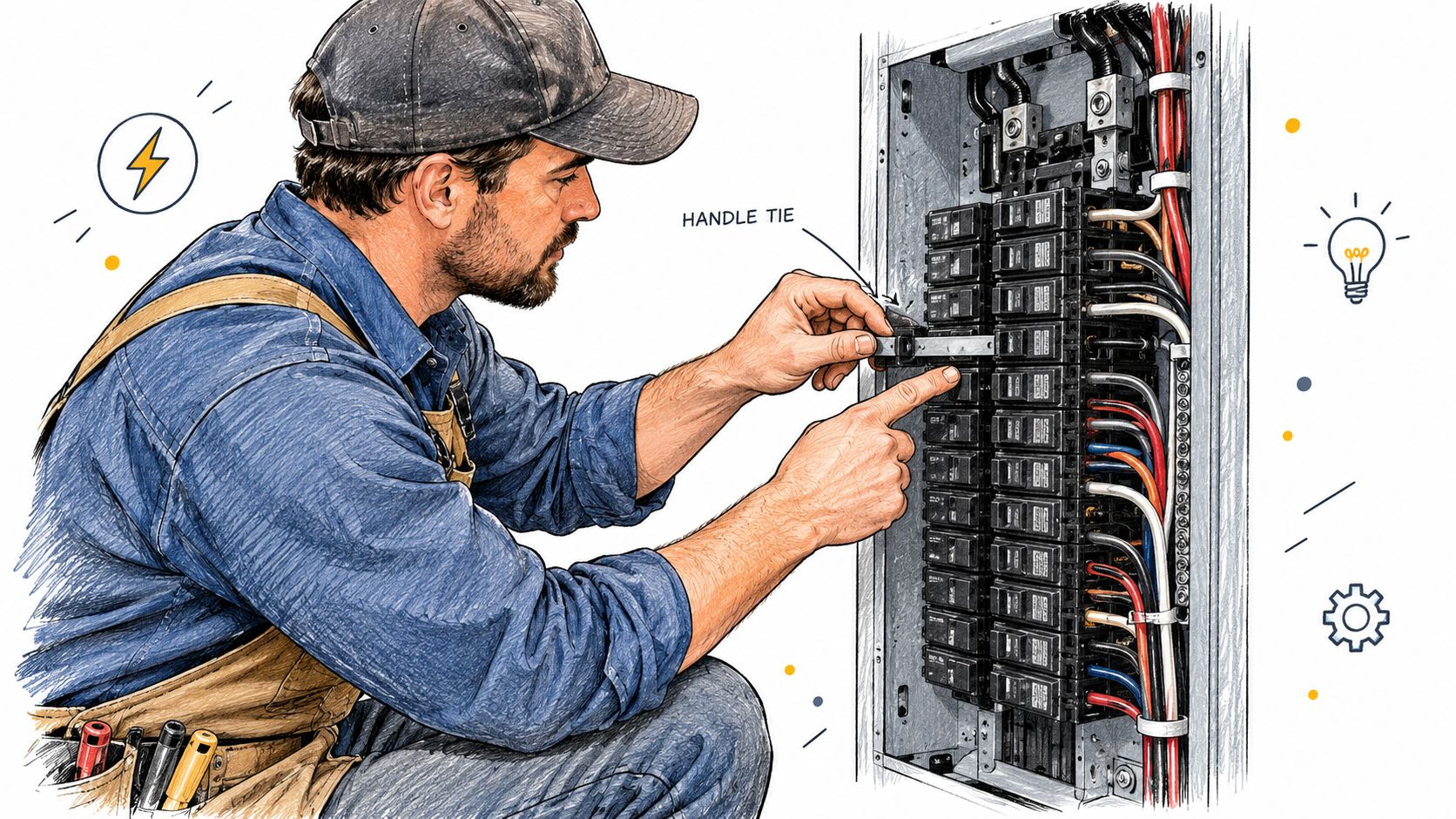
A breaker handle tie is a mechanical accessory used to connect the handles of adjacent single-pole breakers. In a shared-neutral multiwire branch circuit, it gives the electrician one linked operating point for the ungrounded conductors. The purpose is practical. A worker who switches the circuit off manually should not leave one ungrounded conductor energized while assuming the entire circuit is isolated.
The U.S. electrical code addresses this condition directly. NEC 210.4(B) requires a means of simultaneously disconnecting all ungrounded conductors at the origin of a multiwire branch circuit, while NEC 240.15(B)(1) permits individual single-pole breakers with identified handle ties for single-phase line-to-neutral loads. These provisions are summarized in manufacturer guidance on breaker handle ties and multiwire circuits.
What the tie actually does
The accessory transfers movement between the breaker handles. If an electrician manually moves one handle, the connected handle moves with it, creating the required simultaneous manual disconnect when the assembly is properly listed and installed.
That mechanical action is different from automatic operation during an overload or short circuit. A handle tie doesn't necessarily connect the internal trip mechanisms. If one single-pole breaker trips electrically, the other may remain closed. The ABB installation material referenced in the field guidance makes this distinction clear: a handle tie doesn't provide common tripping.
Field rule: A tied pair can satisfy a manual disconnect requirement in an approved application, but it isn't automatically equivalent to a two-pole common-trip breaker.
Why the distinction matters at the panel
The usual mistake is to inspect only the visible handles. A pair may look joined while using an accessory that isn't listed for the breaker, isn't secured correctly, obscures markings, or isn't suitable for the circuit voltage. A proper evaluation also considers the breaker model, panel compatibility, conductor arrangement, load type, and the behavior required when a fault occurs.
The small accessory therefore has two separate jobs in the conversation. It can provide linked manual operation, and it can support a compliant MWBC arrangement when the code and product listing allow it. It can't expand the breaker's electrical rating or supply a common-trip function that the breaker assembly wasn't designed to provide.
NEC Code Requirements for Simultaneous Disconnect
The starting point is the circuit, not the accessory. A multiwire branch circuit uses multiple ungrounded conductors with a shared grounded conductor. Because the conductors share a neutral, a person servicing one portion of the circuit needs a reliable way to disconnect the ungrounded conductors together at the circuit origin.
NEC 210.4(B) requires simultaneous disconnection of all ungrounded conductors of a multiwire branch circuit. That requirement can be met through an approved linked arrangement where the application permits it, or through a breaker assembly designed to operate the poles together. The field question is not whether two handles touch. It's whether the installed means is identified for the breakers and provides the required operation.
NEC 240.15(B)(1) permits individual single-pole breakers with identified handle ties for single-phase line-to-neutral loads. The word identified matters. A listed accessory matched to the breaker series is materially different from a wire, screw, nail, generic clip, or other improvised device.
Voltage rating remains a separate question
A handle tie is a mechanical component. It doesn't change the breaker's voltage rating, interrupting capability, or permitted application. Technical guidance on slash-rated breakers and shared-neutral applications emphasizes that appropriately marked breakers must be used within their voltage-to-ground limits.
A common field shortcut fails here. Two single-pole breakers may each be suitable for line-to-neutral loads, yet the pair may not be appropriate for a line-to-line load just because a handle tie has been added. A slash-rated breaker must be applied within the voltage-to-ground conditions for which it is marked. The tie doesn't turn an unsuitable pair into a compliant device for a different voltage relationship.
What to document on a submittal
For procurement and plan review, document the complete assembly rather than listing only “handle tie.” A useful specification identifies:
Circuit arrangement: State whether the circuit is a shared-neutral MWBC and identify the ungrounded conductors.
Load relationship: Confirm whether the loads are line-to-neutral or whether the conductors supply a line-to-line load.
Breaker series: Name the manufacturer, breaker family, pole configuration, ampere rating, and voltage marking.
Accessory identity: Specify the manufacturer's handle-tie accessory identified for that exact breaker series.
Disconnect behavior: State whether the application needs simultaneous manual disconnect only or common tripping as well.
A plan reviewer or inspector can then verify the actual equipment against the documents. This approach also works well alongside broader arc-flash labeling requirements for electrical installations, because both tasks depend on accurate equipment identification and clear field documentation.
Handle Ties vs Common Trip Breakers
A handle tie and a two-pole common-trip breaker may occupy adjacent positions and present a similar front-panel appearance, but their internal behavior differs. The handle tie links operating handles. A common-trip breaker links the poles' trip functions inside the breaker assembly.
That difference becomes important during a fault. If one single-pole breaker in a tied pair trips, the mechanical tie may not force the other breaker to trip. The remaining breaker can stay closed, leaving part of the circuit energized. A two-pole common-trip breaker is designed so a qualifying trip event on one pole operates the linked trip mechanism for both poles.
Feature
Handle Tie, Single-Pole Pair
2-Pole Common Trip Breaker
Primary linkage
External mechanical connection between operating handles
Internal connection between both poles and their trip mechanisms
Manual operation
Both handles should move together when the listed accessory is correctly installed
Both poles operate together through the factory assembly
Automatic fault response
One pole can trip while the other remains closed because the tie doesn't provide common tripping
A trip on one pole operates both poles through the common-trip mechanism
Procurement check
Accessory must be identified for the exact breaker model and series
Breaker must be the correct factory-listed two-pole device
Typical code question
Is simultaneous manual disconnect sufficient and permitted for this application?
Does the circuit require common tripping or a factory common-trip assembly?
Improvised substitution
Unacceptable. A field-made tie doesn't establish listing or suitability
Not applicable. The common-trip function is built into the breaker
When the handle tie can be appropriate
For a permitted single-phase line-to-neutral MWBC, an identified handle tie can provide simultaneous manual disconnect. The breaker pair still has to be correctly rated, installed in the permitted panel positions, and matched to the manufacturer's accessory. The installer must also account for the actual load and voltage arrangement, rather than assuming every adjacent pair is interchangeable.
The phrase manual disconnect should stay explicit in the specification. It tells the electrician and inspector what the accessory provides, and it prevents the common mistake of treating the pair as though it had an internal common-trip mechanism.
When common trip is the correct choice
A factory two-pole common-trip breaker is the appropriate choice when both ungrounded conductors form a single line-to-line circuit or when the application requires both poles to open under an automatic fault condition. It is also the safer specification when the project documents require common tripping and the manufacturer offers the correct factory assembly.
A handle tie shouldn't be used to approximate a two-pole breaker for a load that depends on both ungrounded conductors being disconnected and tripped together. For breaker sourcing and configuration review, ATEK's circuit breaker product range can be used as one procurement reference, but the final selection still has to match the panelboard, breaker series, rating, and application.
The question isn't “Can these handles be joined?” It's “What must happen when the circuit is manually switched off, and what must happen when one pole trips?”
Types of Handle Ties and Compatibility Rules
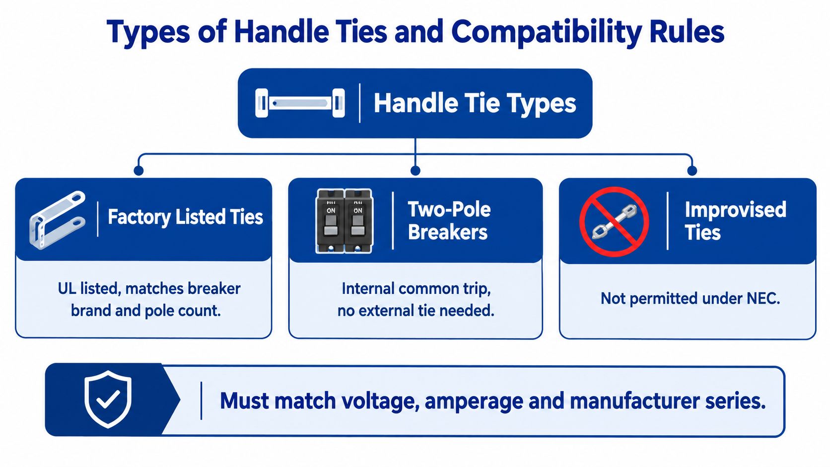
Handle ties aren't universal hardware. A tie that fits one breaker family may not fit another, may interfere with the handle geometry, or may lack the listing needed for that assembly. Procurement should begin with the breaker label and catalog information, not with a visual guess based on handle spacing.
Physical designs you may encounter
Rigid clip systems use a molded accessory that engages the two breaker handles. The clip must match the handle shape, spacing, and breaker family. A loose fit can allow independent movement or damage the handle mechanism.
Metal pin or bar systems use a dedicated connecting piece that passes through or engages designed features in the breaker handles. The installation method varies by manufacturer, so the product instructions control. Drilling, bending, or modifying the breaker face isn't an acceptable way to make a pin fit.
Factory-linked toggles are built into a multi-pole breaker or a manufacturer's integrated assembly. They don't depend on a separately sourced field accessory for the operating linkage, and a common-trip version also contains the required internal trip relationship.
The compatibility matrix
Use this sequence before ordering:
Verification point
Acceptable evidence
Stop and investigate when
Manufacturer
Breaker and accessory come from the identified product family
Brand or product family is unknown
Series and model
Manufacturer literature names the exact series or compatible models
The listing says only “universal” or gives no model range
Pole arrangement
Accessory is designed for the installed adjacent poles
Breakers aren't positioned or configured as the accessory requires
Voltage application
Breaker markings match the circuit's line-to-neutral or line-to-line use
The tie is being used to overcome a voltage-rating mismatch
Listing and instructions
Product literature identifies the accessory for that breaker assembly
The accessory is generic, unmarked, or field modified
Panel acceptance
The breaker is permitted in the specific panelboard
The breaker itself isn't approved for the panel
The exact breaker model and panelboard matter because a physically successful installation can still be electrically or administratively wrong. Older installations are especially prone to substitutions made after the original equipment became unavailable. If the original tie can't be identified, replacing the breaker pair with the correct listed assembly is often more defensible than trying to preserve an uncertain accessory.
What doesn't work
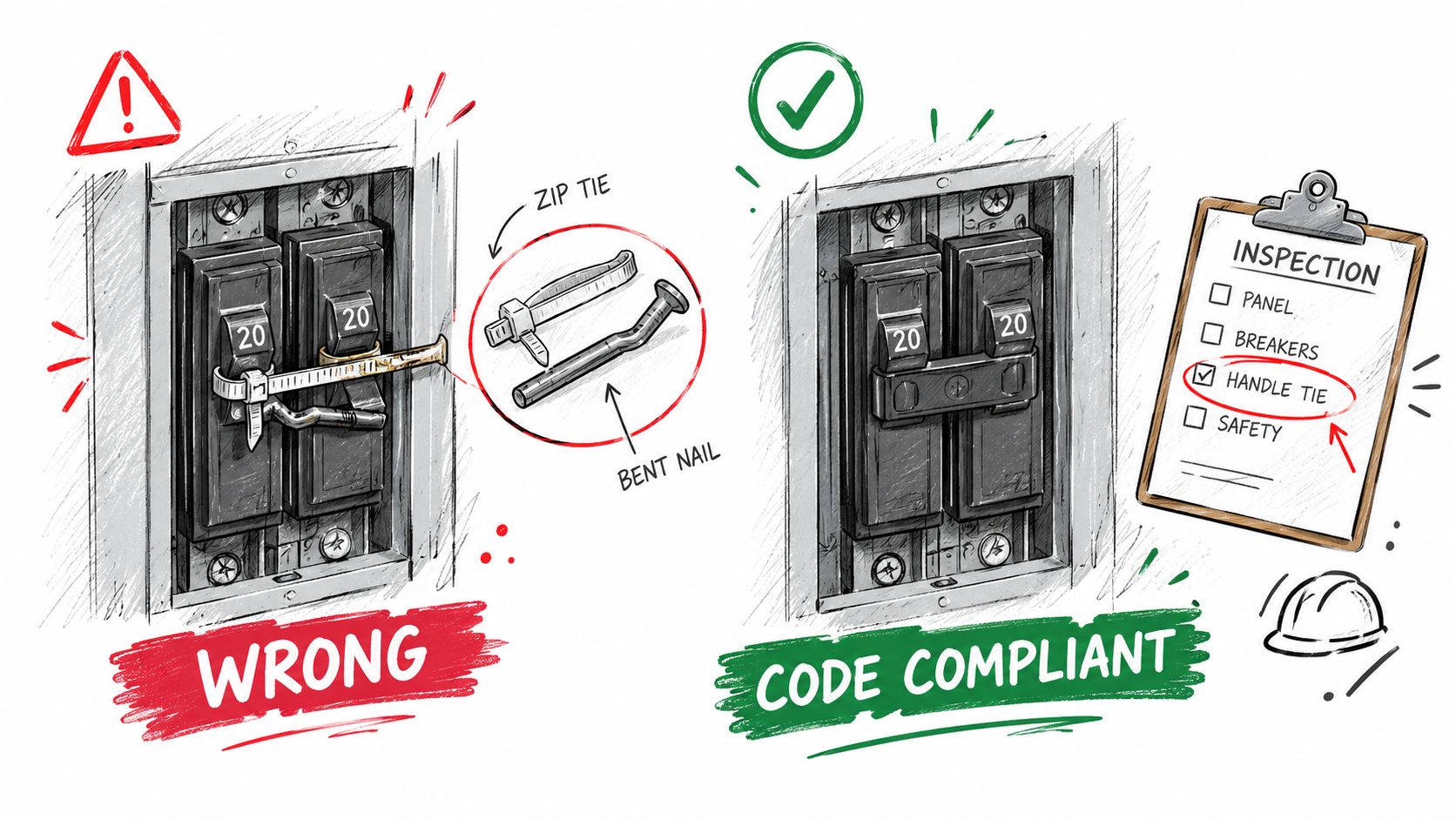
A zip tie, piece of wire, screw, nail, adhesive, or generic plastic clip doesn't establish a listed handle-tie assembly. It may prevent normal handle movement, create stress on the breaker housing, obscure the face markings, or fail during operation. It also gives an inspector no reliable basis for verifying the accessory's suitability.
For retrofit work, record a photograph of the breaker label, panel schedule, catalog designation, and installed tie before placing the order. That information gives the distributor or manufacturer a basis for confirming the accessory instead of guessing from a front-panel image.
UL Listing and Physical Installation Requirements
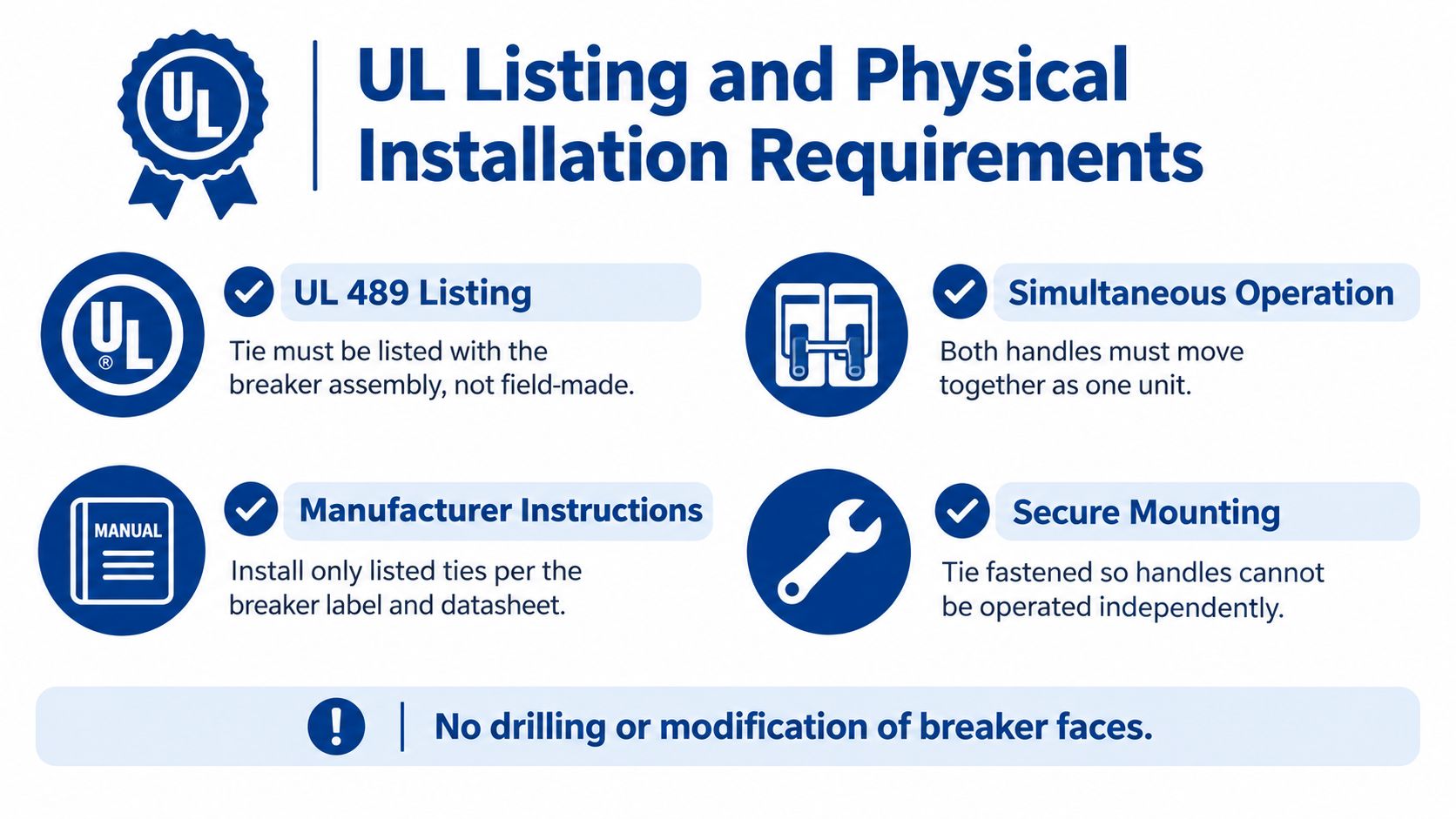
A listed handle tie has physical performance requirements that go beyond “the handles move together.” UL 489-based requirements specify that the tie must operate both breaker handles when either handle is manually operated, must not be readily removable, and must not obscure the ampere marking on either breaker, as summarized in the IAEI technical discussion of slash-rated breakers and shared neutrals.
Installation sequence
De-energize and verify. Follow the site's lockout and verification procedure. Never rely on the panel handle position as proof that the conductors are dead.
Identify the breaker pair. Confirm that the two breakers are the adjacent, compatible units named by the accessory instructions. Check the panelboard listing and circuit schedule.
Set both handles to the same position. The manufacturer's instructions control, but installation generally begins with both breakers in the same physical position, commonly OFF. This avoids forcing one toggle against the other.
Install the listed accessory. Engage the tie exactly as shown in the product instructions. Don't pry, drill, file, bend, or reshape the breaker housing.
Test manual movement. Move either handle through its intended operating path and confirm that both handles move together. A tie that shifts, binds, or permits independent movement isn't ready for service.
Inspect the markings. Confirm that the accessory doesn't hide the ampere marking or other required breaker identification.
Record the assembly. Update the panel schedule and retain the product identification with the project documentation.
Why secure mounting matters
The accessory must not be readily removable during ordinary operation. That doesn't mean a worker can never remove it under controlled service conditions. It means the installed assembly shouldn't behave like a loose cap that can fall away, slide off, or be pulled off without the deliberate procedure intended by the product design.
A secure tie also protects the breaker from misuse. If the accessory doesn't match the handle geometry, the installer may apply pressure to the toggles or housing. That can create a mechanical problem even if the pair appears linked after installation.
The following video can supplement the written instructions, but it doesn't replace the breaker manufacturer's installation documentation or the authority having jurisdiction's requirements.
The final inspection should confirm operation, markings, secure retention, and product identity. Passing a simple movement check doesn't prove that the breaker pair is correct for the voltage or that the tie provides common tripping. Those are separate verification tasks.
Common Field Mistakes and Code Violations
The most serious errors usually start with a reasonable-looking shortcut. Someone sees two adjacent single-pole breakers, needs linked operation, and reaches for whatever is available. The result may hold the handles together physically while failing the listing, compatibility, and fault-response requirements of the installation.
Improvised ties
Nails, screws, wire, zip ties, and cut pieces of plastic aren't substitutes for an identified accessory. They don't establish that the breaker assembly was evaluated with that device, and they may prevent the breakers from moving as intended. A field-made connection can also obscure ampere markings or damage the handle mechanism.
Inspection test: If the installer can't identify the accessory by manufacturer documentation or the breaker assembly's listing information, treat the tie as unverified.
Wrong breaker family
A tie designed for one series may not engage another series correctly, even when the breakers look similar. Different handle dimensions, pole spacing, case geometry, and accessory retention methods can change the result. The same caution applies to older breakers installed in a replacement panel or modern breakers installed in an older panel without confirmation that the combination is permitted.
Confusing adjacent with compatible
Physical adjacency isn't enough. The pair must be the correct poles for the circuit, and the panel must accept the breaker arrangement. A tie installed across breakers that aren't intended to operate as a pair can create an ambiguous panel schedule and a service hazard.
Using a handle tie where common trip is needed
A tied single-pole pair isn't a replacement for a two-pole common-trip breaker when the circuit requires both ungrounded conductors to trip together. This mistake is particularly dangerous on line-to-line loads, where opening one conductor can leave the equipment partially energized.
The same principle applies to projects affected by jurisdiction-specific amendments. Before finalizing a retrofit or inspection response, review the applicable Minnesota NEC changes and confirm which edition and amendments govern the work.
Incomplete documentation
A panel schedule that says only “MWBC” doesn't tell the next technician whether the circuit uses a listed tie or a common-trip breaker. Record the breaker manufacturer, series, ampere rating, voltage marking, accessory identification, and the connected load arrangement. That record reduces repeat troubleshooting when a future service call involves a panel modernization or replacement.
Quick Reference Guide for Multiwire Branch Circuits
Use this field matrix before ordering parts or approving a panel alteration. It separates the manual disconnect question from the automatic trip question, which is where many incorrect substitutions begin.
Circuit condition
Handle tie may be acceptable
Specify a 2-pole common-trip breaker
Single-phase line-to-neutral MWBC
When the code permits the arrangement, the breakers are compatible, and the handle tie is identified for the exact assembly
When the project specification or application requires common tripping
Line-to-line load
Don't treat a handle tie as a substitute based only on linked handles
Use the properly rated factory common-trip assembly
Fault isolation requirement
Not sufficient if one pole must force the other pole open automatically
Appropriate when both poles must trip together
Unknown existing equipment
Only after the breaker series, listing, panel acceptance, and circuit arrangement are verified
Preferred when the existing tie or breaker relationship can't be positively identified
Improvised or generic accessory
Never accept it as a compliant listed solution
Replace with the correct listed breaker assembly
Rapid verification checklist
Trace the conductors: Identify each ungrounded conductor and the shared grounded conductor at the panel.
Confirm the load relationship: Determine whether the loads are line-to-neutral or whether the conductors supply a line-to-line load.
Inspect the neutral: Verify that the grounded conductor is sized, routed, terminated, and identified according to the design and applicable code requirements.
Read the breaker label: Record the manufacturer, series, model, pole count, ampere marking, and voltage marking.
Verify panel acceptance: Confirm that the breaker is listed or identified for the panelboard.
Match the accessory: Require manufacturer documentation naming the exact breaker family and handle-tie accessory.
Check physical position: Confirm that the breakers are in the permitted adjacent positions and that the tie engages both handles.
Operate the assembly: Move either handle manually and confirm that both handles move together.
Check visibility: Ensure the tie doesn't obscure the ampere markings.
Decide on trip behavior: Ask whether the application requires only simultaneous manual disconnect or automatic common tripping.
Update records: Mark the panel schedule and retain the product documentation.
A clean result requires all of these checks to agree. A handle tie that passes the movement test can still be wrong for the voltage application, and a correctly rated breaker can still have the wrong accessory.
Glossary of Related Electrical Terms
Multiwire branch circuit, or MWBC: A branch-circuit arrangement with two or more ungrounded conductors and a grounded conductor that is shared by the circuit conductors. The shared neutral is why the ungrounded conductors need coordinated disconnect treatment at the circuit origin.
Ungrounded conductor: A current-carrying conductor commonly called a hot conductor. In an MWBC, each ungrounded conductor supplies its associated line-to-neutral load and participates in the circuit arrangement that must be evaluated for simultaneous disconnect.
Grounded conductor: The conductor intentionally connected to the grounded system point, commonly called the neutral. In a shared-neutral circuit, it serves more than one ungrounded conductor and must be considered in the circuit design, loading, routing, and maintenance procedure.
Simultaneous disconnect: An arrangement that opens all ungrounded conductors of the applicable circuit at the same time when the disconnecting means is manually operated. NEC 210.4(B) uses this concept for multiwire branch circuits.
Handle tie: A mechanical accessory that links the operating handles of compatible single-pole breakers. It provides coordinated manual handle movement, but it doesn't automatically mean the breakers have common-trip behavior.
Common trip: An internal breaker function that causes the linked poles to trip together when the breaker detects a qualifying fault condition on one pole. A factory two-pole common-trip breaker contains this relationship as part of its breaker assembly.
Two-pole breaker: A breaker assembly with two poles intended to operate as one device. The term alone doesn't communicate every detail of the trip mechanism, so the product documentation must still be checked for common-trip performance and application suitability.
Slash-rated breaker: A breaker marked with a voltage format that distinguishes voltage-to-ground limits from voltage-to-voltage limits. The marking must be applied as intended. A handle tie doesn't change those limits.
Line-to-neutral load: A load connected between an ungrounded conductor and the grounded conductor. This relationship is central to the situations where identified handle ties may be permitted under NEC 240.15(B)(1).
Line-to-line load: A load connected between two ungrounded conductors. It requires careful evaluation of breaker voltage ratings and disconnect behavior. A tied pair shouldn't be assumed to provide the same protection as a factory common-trip breaker.
Identified accessory: A manufacturer-recognized component specified for use with a particular breaker, series, or assembly. For a handle tie, identification means more than physical fit. It connects the accessory to the product listing and installation instructions.
Panelboard: The enclosure and distribution assembly that houses the breakers, bus structure, wiring terminations, and associated equipment. Breaker compatibility must be verified against the panelboard, not just against the breaker's appearance.
Trip-free operation: A breaker characteristic that allows the internal trip mechanism to open the circuit even when the operating handle is being held in the ON position. This is one reason an external handle tie shouldn't be assumed to transfer one breaker's automatic trip action to another.
Ampere marking: The breaker's current rating shown on the device. UL 489-based requirements call for a handle tie that doesn't obscure the ampere marking on either breaker, so the rating remains visible for inspection and service.
Factory common-trip device: A breaker manufactured with internal mechanisms that coordinate the poles during automatic tripping. It is the appropriate specification when the circuit requires both ungrounded conductors to open together during a fault.
Procurement verification: The process of matching the circuit requirements, breaker model, panelboard, voltage marking, accessory listing, and manufacturer instructions before purchase or installation. This is the step that prevents a generic “fits the handle” decision from becoming a field compliance problem.
ATEK Distribution helps contractors, engineers, and facility teams source circuit breakers, panelboard equipment, listed accessories, and related electrical hardware while supporting specification review and compliance documentation. Visit ATEK Distribution with the breaker model, panel information, and circuit requirements when you need a verified replacement or a compatible handle-tie solution.
You're usually not looking up PEX-A pipe support because the easy parts of the job are going well. You're looking because a long run is starting to belly between joists, an exposed corridor needs straighter lines, or an inspector wants to know exactly what support method you're using. That's where support stops being a minor accessory and becomes part of the system design.
PEX-A gives you speed and flexibility, but that flexibility cuts both ways. If you treat it like copper and hang it as an afterthought, it can sag, wander, rub, and telegraph every shortcut in the installation. If you support it correctly, it stays aligned, moves where it should, and looks intentional instead of improvised.
The trade mistake is thinking support is only about passing inspection. Code spacing matters, but it's only the floor. The better question is what kind of support keeps the pipe straight, protects fittings, manages movement, and fits the setting. A home run in a basement ceiling doesn't need the same strategy as a visible domestic-water main in a hospital corridor or a long hydronic run above a corridor grid.
Introduction to PEX A Pipe Support and Why It Matters
A crew can rough in PEX-A fast, pass the pressure test, and still leave behind a run that looks loose once the system heats up and settles. The call-back usually comes from the exposed work. A basement main starts to belly between supports, a corridor run waves under the lights, or a riser shifts enough at a floor penetration to make the whole installation look unfinished.
Support decides more than whether the tubing stays off the ceiling tile. It affects line straightness, thermal movement, fitting load, noise, and how the finished work reads to an owner or inspector. With PEX-A, that matters because the material is flexible by design. Good support uses that flexibility where it helps and controls it where it hurts.
Code spacing gets you compliance
Standard hanger spacing is the starting point for ordinary runs, and in a lot of concealed residential work, that is all you need. If the tubing is protected, the spans are short, and appearance is not part of the job, conventional support at code-accepted intervals will usually pass and perform fine.
Problems show up when installers treat that spacing rule as the whole design. A run can meet the minimum and still droop, snake sideways, or move enough with temperature change to telegraph every hanger location. That is not a code failure. It is a performance and appearance failure.
The real choice is standard support versus controlled support
For short branch lines and home runs above a framed ceiling, regular hangers or approved plastic suspension clips are often the right answer. They install fast, cost less, and allow the tubing to move naturally.
For long visible mains, mechanical room headers, corridor runs, and other exposed work, continuous support channel changes the result. It gives PEX-A a straighter profile, closer to what people expect from copper, while still letting the tube expand and contract in a controlled way. That improves the look of the installation and reduces the tendency for the pipe to dip between points or pull awkwardly at fittings.
That trade-off matters on real jobs.
Where support selection pays off
A few conditions usually justify more thought up front:
Exposed runs: Straightness becomes part of the finished workmanship.
Long horizontal mains: Standard spacing may pass inspection but still leave visible sag.
Risers and floor transitions: Better control keeps the pipe aligned through penetrations and near supports.
Warm-water and hydronic piping: Thermal movement is more noticeable and needs room to happen without noise or side loading.
Plumbers look at support one way. Specifiers look at it another. Owners usually notice only when the pipe looks crooked.
The best support method matches the run. Use standard hangers where they are enough. Use continuous support where the job calls for a straighter line, better movement control, or a finish that does not look like an afterthought.
How PEX A Pipe Support Works and Key Terminology
PEX-A support isn't one device. It's a group of parts that each do a different job. If you mix up those jobs, the installation may hold pipe in place while still creating stress, noise, or poor alignment.
The basic terms that actually matter on site
A support carries the pipe's weight. That can be a clip, clamp, hanger, bracket, or channel assembly. Its first job is load.
A hanger suspends the pipe from structure. Clevis hangers and loop hangers are common examples overhead. Hangers hold the pipe up, but depending on how they're installed, they may either allow movement or fight it.
A clamp grips the pipe more directly. Some clamps are meant to locate tubing in framing or on strut. Others are meant to hold position more firmly. Clamp selection matters because too much grip can prevent the tubing from moving as it expands and contracts.
A guide keeps the pipe tracking in a controlled direction while still allowing axial movement. In practice, a guide is what helps a long run stay orderly rather than wandering side to side.
A fixed point is where you intentionally restrain movement. That's important near valves, at direction changes, and at terminations. A support system that has lots of hangers but no real fixed-point strategy can still let the system push load into the wrong place.
A continuous support channel is different from isolated clips or hangers. It backs the pipe along a longer length rather than only at selected intervals. That changes deflection, appearance, and how the run behaves.
Why PEX-A support is not the same as copper support
PEX-A is flexible by design. That makes it easier to route, especially in framed walls and overhead spaces with obstacles. It also means the pipe responds more visibly to heat, gravity, and support spacing than rigid metallic pipe.
That difference changes your support logic:
Copper thinking: Hold line and elevation with rigid spacing and the pipe largely stays there.
PEX-A thinking: Support the load, allow planned movement, and control the shape of the run.
A support that's too tight can be as wrong as one that's too far apart.
In a domestic water layout, a clip at a framing member may be enough to keep a branch organized. In a hydronic main overhead, that same clip pattern may leave the run looking loose. In other words, the same tubing may need a different support strategy depending on where it lives and how visible it is.
Types of PEX A Pipe Supports and Clips Explained
There isn't one universal support for PEX-A. The right choice depends on whether the run is concealed or exposed, whether movement needs to be guided or restrained, and how much rigidity the finished work should show.
Snap clips and simple framing supports
Plastic snap clips are common for branch lines and organized tubing runs in wood or light-gauge framing. They're fast, inexpensive, and good at keeping spacing tidy in concealed work.
They're not what you use when you want the pipe to look rigid. They also need to be selected carefully so the tubing isn't pinched or forced against rough edges.
Cushioned clamps and metal restraints
Metal clamps with cushioning are useful where the pipe needs a cleaner hold or where vibration and contact noise are concerns. These show up in mechanical spaces, utility rooms, and transitions where tubing comes off equipment or enters more structured support assemblies.
They work well when you need a more intentional mounting point. They work poorly when someone overtightens them and turns the clamp into a brake.
Clevis and loop hangers overhead
For overhead work, clevis and loop-type hangers are familiar hardware and still useful with PEX-A when they're sized and arranged correctly. They help with suspension from rod and strut assemblies and make sense in shared support systems.
Their limitation is appearance and control over long straight runs. A suspended run on isolated hangers can still look uneven even when it technically meets spacing.
Strut-mounted supports and trapeze style assemblies
When a job has multiple parallel lines, strut starts making sense. It gives you a repeatable support plane, cleaner alignment, and easier coordination with other trades. It also makes future changes less painful because the support path is already there.
For support hardware and related mounting options, contractors often source through suppliers that handle broader fasteners and hardware inventory. That matters most when pipe support has to coordinate with framing, anchors, strut, rod, and attachment points from the same package.
Continuous galvanized support channels
PEX-A behaves more like a deliberately aligned system than a flexible tube hanging in space. A continuous support channel carries the tubing along its run, cuts down visible sag, and gives exposed work a much straighter line.
Use it when appearance matters, when spans are longer, or when you need better control of geometry near fittings and mains.
Quick selection cues
Concealed residential branches: Snap clips or simple tubing supports are usually enough.
Mechanical room transitions: Cushioned clamps help with control and contact protection.
Parallel overhead runs: Strut-mounted supports keep the layout orderly.
Exposed commercial mains: Continuous channel is often the cleaner choice.
Near valves and changes in direction: Think restraint and fixed-point logic, not just hanger count.
If the support hardware makes the pipe look accidental, it probably isn't the right support for exposed work.
PEX A Support Spacing Requirements for Horizontal and Vertical Runs
A run can pass rough inspection at standard hanger spacing and still look loose by finish day. That happens all the time with PEX-A on long horizontals, especially where the piping stays exposed and the owner expects straight lines instead of soft dips between clips.
For baseline support intervals, use the common PEX benchmark noted earlier in this article: horizontal runs are typically supported at 32 inches on center for 2 inch and smaller tubing, and vertical runs at 10 feet on center for 2 inch and smaller tubing. Separate code-acceptance guidance also recognizes 10 foot vertical spacing with a mid-story guide for those sizes (Plastic Pipe Institute code acceptance guidance).
Another installation reference notes a similar pattern: 32 inches is a common horizontal limit for 1 inch and smaller, some larger diameters may be permitted at wider intervals depending on code, and vertical runs often call for support at floor levels plus a mid-story guide (PEX plumbing design and installation guide excerpt).
Standard PEX support spacing by orientation
Orientation
Pipe Size
Maximum Spacing
Notes
Horizontal
2 inches and smaller
32 inches
Common benchmark for standard point supports
Vertical
2 inches and smaller
10 feet
Confirm whether a mid-story guide is required
Horizontal
1 inch and smaller
32 inches
Common benchmark in design guidance
Horizontal
Larger diameters
Varies by code and size
Verify the listing, manufacturer instructions, and local code
Vertical
Riser applications
Floor-level support plus mid-story guide
Common method for riser control
Those numbers answer the inspection question. They do not answer the performance question.
On concealed residential branches, 32 inch hanger spacing is usually fine. The tubing is out of sight, the runs are shorter, and a little natural sweep between supports does not create a service problem. On an exposed basement main, overhead corridor run, or mechanical room distribution header, the same spacing often leaves the line looking wavy. That is not a code violation. It is still poor-looking work.
Inspectors usually check four things first:
Support spacing
Proper securement at the run
Compatibility with the pipe and support hardware
Compliance with the approved installation method and local code
Owners, maintenance staff, and other trades notice something else. They see sag between hangers, fittings pulled slightly out of line, movement at valves, and tubing that rubs framing or duct supports when hot water cycles through.
That is the trade-off. Standard hangers are often enough to meet minimum spacing rules. Continuous support becomes the better choice when you want the run to stay straighter, control thermal movement better, and read more like rigid piping.
A practical field check helps. Look at the run and answer these questions before laying out hangers:
Is the piping concealed or exposed?
Is the run short and broken up, or long and uninterrupted?
Are there valves, branches, or transitions that need alignment control?
Will thermal expansion make the tubing snake or rub if it hangs only at intervals?
If the run is concealed and ordinary, standard spacing is usually the right answer. If the run is exposed and expected to look organized, minimum spacing is only the starting point.
Local code, the pipe manufacturer, and the support system listing still govern the final layout. On site, the best support pattern is the one that passes inspection, keeps the tubing free to move where it should, and keeps the finished run straight enough that nobody asks why it looks like it was added later.
Continuous Support Channel Systems for Longer Spans
When people want PEX-A to look straighter and behave more like a rigid piping system, continuous support channel is usually the turning point. This is the method that changes the conversation from “How many hangers do I need?” to “How do I want this run to perform?”
An authoritative installation guide for PEX-A describes a 23-gauge galvanized-steel horizontal support channel and states it allows a maximum horizontal span of 8 ft for 3 in nominal and smaller piping, with 1-1/2 in and smaller fittings supported within 12 in. The same guide states that vertical PEX-A piping should be supported every 5 ft in-wall and at the base of each floor for risers (Uponor PEX hydronic piping support guidance).
What the channel actually changes
A continuous channel spreads support along the run instead of forcing the tubing to bridge from point to point. That does a few useful things at once:
Cuts visible deflection
Keeps fittings better aligned
Produces cleaner parallel runs
Makes exposed work read more like planned piping than flexible tubing
For long commercial corridors, hydronic mains, and visible domestic-water distribution, that difference is easy to see. It also helps in congested overhead spaces where keeping geometry consistent matters.
What it does not replace
Continuous support channel is not a free pass to ignore restraint design. The same guidance notes that clamps and fixed points still have to follow the PEX design and installation manual. In plain language, the channel supports the run, but it does not replace system control at changes in direction, valves, or terminations.
That's where some installations go wrong. The pipe is beautifully straight in the middle and poorly restrained at the ends. Then movement shows up where the system is most vulnerable.
For related support infrastructure in mixed-trade overhead systems, many teams also coordinate with suppliers handling conduit, raceway, and cable support products. The overlap is practical. Shared strut, trapeze support, and coordination space often affect how plumbing support can be laid out cleanly.
When to specify channel instead of isolated hangers
Choose continuous channel when:
The run is long enough that standard spacing will telegraph sag
The pipe stays exposed after turnover
The layout needs copper-like visual discipline
The job has repeated mains where consistency matters
Use isolated hangers when the run is short, concealed, or not appearance-sensitive. Channel isn't mandatory everywhere. It's just the better answer in the wrong places for ordinary clips and hangers.
Installation Best Practices for Secure and Movement Friendly Support
A PEX-A main can be fully within hanger spacing and still look bad or move badly after startup. I see it on jobs where the pipe was supported often enough to satisfy the spacing table, but the run still waves between hangers, rubs a stud edge, or shoves thermal movement into a valve body because the supports were installed with no plan.
What good support installation looks like
Good support does two jobs at once. It carries the weight of the tubing and water, and it lets the pipe move where the system is supposed to move. Manufacturer guidance is clear on the basics. Supports need to allow free tubing movement and avoid contact points that can nick, cut, or wear into the pipe over time.
That matters whether you are using standard hangers at code spacing or a continuous channel under a long exposed run. Standard hangers are often enough in short concealed runs where appearance is irrelevant and movement is modest. Continuous support earns its keep where the pipe stays visible, where a long main would telegraph sag, or where the owner expects the run to stay straight like copper.
A few field rules make the difference:
Wood framing: Drill clean holes, sleeve or protect penetrations where required, and avoid clips that flatten the tubing.
Metal studs: Treat every cut edge as a potential abrasion point. Use isolating bushings or support components that keep the tube off sharp steel.
Masonry and concrete: Anchor to structure with hardware sized for the load, then use supports that cradle the pipe instead of pinching it.
Strut and trapeze: Set the supports in line before snapping in the tube. A straight support layout produces a straight run.
Common mistakes that create callbacks
The usual callback is not an immediate leak. It is noise, a crooked exposed line, a rubbed spot, or a fitting area that takes movement it should never have seen.
These are the misses that show up later:
Clamps tightened hard against the tube: The pipe cannot slide, so expansion gets pushed to fittings, branches, and changes in direction.
Hangers with narrow or rough contact points: The pipe may pass test and still wear during normal thermal cycling.
No support strategy near valves and heavier components: The tubing ends up carrying weight that should be transferred to structure.
Supports installed by convenience instead of alignment: The run wanders, especially in open ceilings where every offset is visible.
Support the run where it needs control, not only where structure is easy to hit.
One simple check catches a lot. Sight down the run before test and before insulation. If it already has dips, doglegs, or side load at a fitting, fix it while everything is open. PEX-A will not straighten itself after the ceiling closes.
Match the support method to the result you want
If the goal is only to meet minimum spacing, isolated hangers may be enough. If the goal is a straight exposed main that moves in a controlled way and still looks disciplined at turnover, treat support as a performance and appearance decision. That usually means better alignment, better guidance at penetrations, and in some cases continuous support instead of point supports alone.
Crews also need to work safely while drilling overhead, setting anchors, and laying out trapeze or strut. A practical OSHA checklist for overhead fastening and support work helps cover the basics before the job turns into ladder, lift, and anchor work.
The cleanest installations come from crews who know which supports are carrying load, which supports are guiding movement, and where restraint has to occur so the pipe stays straight and the fittings stay out of trouble.
Fire Ratings Insulation and Adjacency Considerations
A PEX-A run can be perfectly spaced and still fail the job if it crosses a rated corridor, crowds a can light, or gets pinned hard against another service in the ceiling. I see that on remodels all the time. The tubing is supported, but the assembly around it was never checked.
Fire rating and listing conditions can change what support method is acceptable. As noted earlier in the manufacturer literature, some ASTM E84 use conditions depend on insulation at unsupported pipe or fittings, and the relaxed separation rules for parallel runs apply only when those conditions are met. That is not a detail to sort out after the run is already hung.
Why support decisions change in crowded ceilings
Open joist bays are forgiving. Rated chases and mixed-trade plenums are not.
In those spaces, support choice affects more than spacing compliance. It determines whether the tubing can hold its route, stay off heat-producing components, avoid abrasion at contact points, and maintain whatever insulation or assembly condition the listing calls for.
That matters with recessed lighting, vent connectors, duct takeoffs, cable tray, and access panels. PEX-A needs room to move with temperature change, but it also needs controlled position. If the run snakes between other trades on loose point supports, it can drift into a bad adjacency even though every hanger is technically present.
Continuous support helps, but it does not override the assembly
The performance-versus-appearance decision gets practical. Standard 32-inch hanger spacing is often enough for concealed utility piping where the main goal is code compliance and basic control. In exposed work, crowded ceilings, or rated routes where the pipe needs to stay exactly where it was designed, continuous support channel can do a better job of keeping the run straight and limiting side-to-side wander.
That extra control helps preserve clearance to nearby systems. It also gives the finished run a more disciplined look. But continuous support does not cancel fire-resistance or listing requirements. If an assembly calls for insulation, minimum separation, or specific treatment at penetrations, the straighter support method still has to follow those rules.
What to check before the ceiling closes
On site, I check four things before signing off on support in rated or congested areas:
whether the fire-resistance or flame-spread condition requires insulation at exposed or unsupported sections,
whether nearby fixtures or piping create heat or clearance problems,
whether the support method keeps the tubing guided without hard rubbing,
and whether the run will stay in place after insulation, other trades, and test conditions put it under load.
A neat run that ignores fire, insulation, or adjacency rules still fails inspection. A run that meets spacing but looks sloppy in open view is also a missed opportunity. Good support work does both. It protects the assembly and keeps the piping straight enough to look intentional.
Quick Reference Lookup Cross References and Related Resources
For quick field use, the decisions usually boil down to three checks. First, determine whether you're working from standard isolated support spacing or an approved continuous support channel system. Second, decide whether the run is concealed utility piping or appearance-sensitive exposed piping. Third, look at nearby conditions such as fittings, risers, heat sources, and shared ceiling space.
Fast lookup by situation
Short concealed branch run: Standard clips or hangers are usually the practical choice.
Visible overhead main: Consider continuous support if straightness matters.
Riser through multiple levels: Treat it like a controlled vertical run, not just a stack of loose supports.
Congested ceiling or rated assembly: Check insulation, adjacency, and movement requirements before choosing hardware.
Cross references that help on site
If you're deciding between hardware types, use these pairings:
Question
Best section to revisit
Which support hardware fits this run?
Types of PEX A Pipe Supports and Clips Explained
What spacing will pass inspection?
PEX A Support Spacing Requirements for Horizontal and Vertical Runs
How do I keep a long run straighter?
Continuous Support Channel Systems for Longer Spans
How tight should supports be installed?
Installation Best Practices for Secure and Movement Friendly Support
What changes in rated or crowded spaces?
Fire Ratings Insulation and Adjacency Considerations
Short glossary for practical use
Guide: A support that controls path while allowing movement along the tubing.
Fixed point: A deliberate restraint location used to control where movement goes.
Isolated hanger: A single support point rather than a full-length backing system.
Continuous channel: A support member that backs the tubing along a longer run.
Mid-story guide: A vertical-run control point used between floor supports where required.
The main takeaway is that PEX-A pipe support is not only a spacing question. It's a decision about how the system will look, move, and age in the specific building you're working on. If you separate compliance from performance in your planning, support choices get much clearer.
ATEK Distribution supplies electrical and infrastructure support hardware that often intersects with mixed-trade overhead work, including clamps, mounting components, and support-related procurement help for coordinated installations. If your project needs sourced support hardware, compliance documentation, or help finding hard-to-get components around shared ceiling and utility systems, visit ATEK Distribution.
The crew has set a motor on its housekeeping pad, the feeder is already stubbed in, and someone needs a flexible connection between the box and the terminal enclosure. The material request says “1-inch flex,” but that shorthand leaves several decisions unresolved. Is the connection dry and indoors, or exposed to water and oil? Will the whip stay within the permitted bonding length? Can the conductors make the turn without forcing the conduit below its bend limit?
Those questions determine whether standard flexible metal conduit, liquidtight flexible metal conduit, or a larger raceway belongs on the purchase order. The trade size alone doesn't guarantee a workable installation. A fitting that doesn't match the conduit, a crowded terminal compartment, or a tight bend can turn a routine equipment connection into damaged insulation, rework, and an inspection problem.
Understanding 1-Inch Flexible Metal Conduit Applications
A typical installation uses 1-inch flexible metal conduit as the final connection to a motor, transformer, disconnect, rooftop unit, or piece of industrial machinery. Rigid raceway brings the circuit close to the equipment, then the flexible section absorbs vibration and handles the small alignment differences that occur between the equipment and the stub-up.
That role matters. A machine may shift slightly during setup, a motor may transmit continuous vibration, and an equipment pad may not line up perfectly with the conduit stub. Standard FMC gives the installer room to make that connection without forcing rigid conduit into an awkward offset. The conduit also makes future equipment service more practical, because technicians can disconnect or reposition the unit without cutting apart a rigid run.
Why the trade size is useful
A 1-inch flexible metal conduit installation occupies less space than a larger whip while still providing useful conductor capacity for equipment connections. Product references show an inside diameter near 1.00 to 1.04 inches and an outside diameter around 1.30 to 1.38 inches, depending on construction, as documented in Southwire's flexible metal conduit data.
That makes 1-inch FMC a practical middle ground. It can route through a crowded mechanical room more easily than a larger trade size, but it isn't a miniature raceway. The installer still has to coordinate hubs, fittings, enclosure entries, conductor size, bend space, and support.
Field rule: Treat a 1-inch whip as an engineered equipment connection, not as leftover flexible raceway that can be bent into whatever space remains.
Where installations go wrong
The common failure isn't always a wrong conductor count. It's often a conduit that leaves the box at an aggressive angle, runs directly into a motor connection box, or is pulled tight enough to transfer vibration into the termination. The interlocked profile can deform when installers force a sharp turn, and the resulting restriction makes conductor pulling harder and increases the chance of insulation damage.
Support also matters. FMC needs to be secured and terminated in a way that keeps its weight and movement from loading the box or equipment fitting. A long unsupported whip may function electrically while still creating a mechanical problem. If the connection needs a longer path, more protection, or a grounding arrangement beyond the permitted conditions, a different raceway strategy may be more appropriate.
Categories of Flexible Metal Raceways
The first procurement decision is environmental. Standard FMC and LFMC may share a 1-inch trade size, but they serve different installation conditions. FMC is the interlocked metal raceway used under NEC Article 348 and governed by UL 1, while LFMC is the jacketed liquidtight product covered by NEC Article 350 and UL 360. The applicable requirements are summarized in the manufacturers' FMC and LFMC product references.
Standard FMC for dry locations
Standard FMC has a spiral interlocked metal construction without the continuous outer jacket used on liquidtight products. It's a sensible choice for dry indoor equipment connections where the raceway doesn't face washdown, standing water, outdoor exposure, or conditions that can introduce liquids into the wiring method.
It works well around indoor motors, control cabinets, dry mechanical rooms, and equipment that needs vibration isolation. It's also generally easier to inspect visually because the metal profile remains exposed. That simplicity doesn't remove the need for listed fittings, proper support, or correct bonding.
LFMC for wet and exposed equipment
LFMC adds a nonmetallic outer jacket over the metal core. The jacket helps provide a liquidtight wiring method for machinery, HVAC equipment, outdoor gear, and locations exposed to water or oil. A representative 1-inch LFMC specification lists an inner diameter of about 1.041 to 1.066 inches, an outer diameter of about 1.290 to 1.315 inches, and an 8-inch minimum bend radius, with compliance references including UL 360 and NEC Article 350 in Southwire's LFMC specification.
Ordering standard FMC for an outdoor HVAC unit is a predictable mistake. The metal conduit may be physically flexible, but it doesn't provide the same liquidtight protection. Conversely, using LFMC in every indoor connection can add cost, increase outside handling dimensions, and require fittings that don't match the standard FMC system.
For broader raceway comparisons, the distinctions discussed in this EMT versus rigid conduit guide help place flexible raceways in the larger installation plan. Choose the construction based on the environment first, then verify the fitting system, listing, and enclosure requirements.
Physical Specifications and Bend Radius Limits
A one-inch whip can fail before the pull starts. The trade size identifies the raceway category, not its exact outside profile. That difference affects knockout selection, enclosure hubs, sleeve clearance, prefab dimensions, and terminal-compartment space. Confirm the approved manufacturer's submittal before releasing fittings or cutting assemblies.
The 8-inch minimum bend radius is the smallest radius permitted by the manufacturer, not a target for forcing the raceway around an obstruction. A sharper turn can distort the interlocked armor, raise pulling friction, and restrict conductors inside the bend. The problem may remain hidden after the whip is installed.
Lay out the route before cutting. Account for the fitting body, enclosure entry, conductor exit, and the bend needed to reach the terminals. A short connection may still require more room than the centerline drawing shows, particularly where several conductors enter a crowded motor or equipment box.
That routing check often determines whether one-inch FMC is practical. If the bend cannot maintain its radius without crowding the termination, use a longer offset, change the equipment entry, or step up to a larger trade size. If water or oil exposure also governs the connection, evaluate LFMC rather than forcing standard FMC into a location it does not suit.
Coordinate the real envelope
BIM coordination should show more than the raceway centerline. Include the actual outside diameter, fitting, locknut or hub, and the clearance needed to install and tighten the connection. LFMC also requires room for its jacket and sealing components, even where its listed outside dimensions differ from standard FMC.
Prefab check: Verify outside diameter and bend radius from the selected manufacturer before building a batch of whips. A trade-size label alone is insufficient for fabrication.
Fittings and Termination Methods
A flexible raceway performs only as well as its terminations. The fitting has to match the conduit type, enclosure entry, location rating, and bonding method. A standard FMC connector isn't a substitute for an LFMC liquidtight connector, and a fitting that grips the wrong portion of the conduit can fail the mechanical connection even when the raceway itself is listed.
For standard FMC, select a connector designed for the specific conduit construction and the enclosure entry. The connector must seat the conduit fully, engage the interlocked armor as intended, and provide a secure connection to the box or equipment. Verify the knockout or threaded opening rather than assuming every 1-inch entry uses the same physical geometry.
Choosing the termination
Set-screw-style fittings can be efficient in suitable indoor applications, particularly where the connection is accessible and the fitting is listed for the FMC construction. Compression fittings use a mechanical compression action that can provide a firm connection and are often useful where a more controlled grip is preferred. The correct choice depends on the listing, enclosure, location, and project specification, not just installer habit.
For LFMC, use a listed liquidtight fitting made for the jacketed conduit. The fitting's sealing components must engage the jacket correctly, while the internal metal core must remain bonded through the fitting system. A loose seal can admit moisture, and an improperly seated core can compromise both mechanical security and electrical continuity.
The broader selection of flexible conduit fittings includes connectors, couplings, elbows, adapters, reducers, bushings, and locknuts. Match each component to the raceway and termination rather than mixing parts from unrelated systems.
A practical installation sequence
Prepare the cut. Make a clean, square cut with the approved tool. Remove sharp metal that could damage conductors or prevent the fitting from seating.
Install the connector components. Follow the fitting manufacturer's order for locknuts, bushings, sealing rings, grounding cones, and compression parts.
Seat the conduit fully. Don't stop when the conduit merely touches the fitting. The metal core or armor must engage the connector as designed.
Tighten and inspect. Check the fitting for movement, verify the locknut or hub is secure, and perform the physical tug check required by the installation practice.
Protect the conductors. Confirm that no sharp edge, exposed armor, or displaced sealing component can contact the insulation.
A short visual demonstration can help crews understand how the fitting components stack and lock together.
The fitting should remain accessible during inspection and service. Burying a questionable termination behind equipment makes a small installation error expensive to correct.
Conduit Fill and Real-World Pullability
A fill table answers only one question: whether the conductor area is within the permitted raceway capacity. It doesn't tell you whether the crew can pull the conductors through a corrugated metal interior, around a tight equipment offset, and into a crowded terminal box without damaging insulation.
For 1-inch FMC, an NEC-based fill table lists capacity of 33 one 14 AWG conductors, 24 of 12 AWG, 15 of 10 AWG, and 9 of 8 AWG in the applicable table entries at Elliott Electric's conduit fill reference. Those figures are useful for code calculation, but they're not a recommendation to load every whip to the mathematical limit.
Why the table and the field disagree
FMC creates more friction than a smooth raceway because the conductors pass over an interlocked interior profile. Every bend adds resistance, and the final turn into a device box can be more difficult than the straight portion. Conductor insulation can scrape against the metal profile when the pull tension rises, especially if the installer yanks the bundle rather than controlling it.
The practical limit also depends on conductor diameter, insulation type, route length, number of bends, temperature, and access at both ends. A conductor count that looks harmless on paper may become a poor choice once the crew has to make a tight equipment connection and leave enough slack for termination.
Pull planning that saves rework
Count conductor area. Use the actual conductor dimensions from the approved wire data, not a rough assumption based only on AWG.
Plan the route before pulling. Keep the conduit as straight and gently curved as the equipment layout allows.
Protect the insulation. Use an appropriate pulling compound where the manufacturer and installation conditions allow it, and control the pull instead of exceeding the conductor's handling limits.
Separate crowded terminations from raceway sizing. A conductor bundle may fit the conduit yet fail to fit comfortably in the equipment box.
Estimator's judgment: If the crew needs excessive force to complete a 1-inch pull, the raceway is already too small for the job, even if the fill calculation passes.
Stepping up to a larger trade size can reduce pulling effort, conductor damage risk, and termination congestion. The decision should account for the full installed cost, including labor, damaged wire, replacement fittings, and the delay caused by a failed pull. For cable and conductor selection, keep the actual wire construction aligned with the raceway plan, using a supplier that can verify dimensions and compatibility through its wire and cable offerings.
Bonding and Grounding Requirements
FMC can serve as a bonding path in permitted installations, but that permission has conditions. NEMA guidance identifies FMC bonding under the applicable requirements of NEC Articles 348 and 250, including a 6-foot bonding-length limit, as described in the NEMA FMC guidance document.
That limit changes the procurement question. If a 1-inch FMC connection exceeds the allowed length, the installer needs a separate equipment grounding conductor. The same decision may apply when the environment, equipment, or circuit conditions make reliance on the flexible metal wall unsuitable.
Don't confuse continuity with durability
A meter can show continuity during commissioning while the long-term grounding path remains vulnerable. Corrosion at joints can increase resistance over time, and repeated vibration can affect mechanical interfaces. Damp, outdoor, washdown, or corrosive facilities deserve a more conservative specification, particularly where maintenance access is poor.
A separate equipment grounding conductor gives the fault-current path an independent route through the flexible connection. It doesn't eliminate the need to bond the raceway correctly, but it reduces dependence on the interlocked metal profile and its terminations.
Check both ends
Inspectors and commissioning teams should be able to verify the bonding path at the box and at the equipment. Confirm that the fitting is listed for the raceway, that the connection is mechanically secure, and that any required bonding jumper or internal grounding conductor is continuous between terminations.
Use a dedicated grounding conductor when the connection length, installation environment, equipment design, or governing electrical requirements call for it. Don't make the field electrician infer that requirement from a vague material description such as “1-inch flex.” Put the raceway type, fitting type, length, and grounding method on the submittal or material schedule.
Cross-References to Related Raceways
1-inch FMC solves a specific problem. It provides a flexible, metal connection between fixed infrastructure and equipment that moves, vibrates, settles, or needs service access. It isn't automatically the right replacement for EMT or rigid metal conduit on a long exposed run.
Decision matrix for common choices
Raceway
Best use
Strength
Limitation
1-inch FMC
Final equipment connections in suitable locations
Handles vibration and alignment changes
Limited by bend radius, support, bonding conditions, and pullability
EMT
Long, straight indoor runs
Efficient for organized routing and broad infrastructure paths
Doesn't accommodate equipment movement or terminal misalignment well
RMC
Areas requiring stronger physical protection
Robust protection for severe exposure
Heavier, slower to install, and less practical for routine flexible connections
EMT usually earns its place on straight ceiling routes, wall runs, and organized distribution paths. It provides a clean, rigid pathway, but it becomes awkward at motor terminals and vibrating equipment. Trying to force EMT into the last connection often produces offsets that consume space and make service more difficult.
RMC belongs where physical damage is a serious concern or where the project specification requires a heavy-duty metallic raceway. Its strength is valuable in exposed industrial areas, loading zones, and other locations where a lighter raceway may not provide enough protection. Its weight and installation effort make it a poor default for every equipment whip.
Build a hybrid system
Many good installations use more than one raceway type. EMT carries the fixed run, a box or disconnect provides the transition, and FMC or LFMC handles the final equipment connection. That arrangement puts each wiring method where it performs best instead of making one product solve every condition.
For outdoor equipment, the flexible portion needs the environmental protection of LFMC and fittings designed for that product. For dry indoor machinery, standard FMC may be adequate, provided the bend, support, termination, fill, and bonding requirements are satisfied.
The right question isn't “Which raceway is cheapest per foot?” It's “Which combination gives the crew a secure, serviceable, inspectable path with the fewest avoidable transitions?” Material price matters, but so do fitting labor, pulling time, equipment access, and the cost of reopening a completed connection.
Quick Reference and Procurement Checklist
When a purchase request says 1-inch flexible metal conduit, stop and clarify the installation before releasing material. A complete order identifies the raceway, environment, fittings, grounding method, and conductor plan.
Confirm the raceway
Choose the construction: Specify standard FMC for the intended dry-location application, or LFMC where the wiring method must resist liquid exposure.
Verify the listing: Match standard FMC to the applicable UL and NEC requirements, and confirm LFMC documentation includes its required liquidtight listing.
Check the dimensions: Use the manufacturer's inner and outer diameters for enclosure entries, hubs, sleeves, and BIM coordination.
Record the bend requirement: Preserve the manufacturer's minimum bend radius in the layout and prefab drawing.
Confirm the fittings
Match the connector: Use fittings listed for the exact FMC or LFMC construction.
Coordinate the entry: Verify knockout, hub, locknut, bushing, and enclosure compatibility before shipment.
Specify the sealing parts: LFMC installations need the fitting components that maintain the liquidtight rating.
Plan service access: Don't place a termination where the crew can't inspect or retighten it.
Confirm the conductors and bonding
Calculate actual fill: Use conductor area and the applicable fill table. Don't treat the listed maximum as the preferred field load.
Review the pull route: Account for bends, friction, conductor insulation, and terminal-box space.
Check the length: Determine whether the FMC connection stays within the permitted bonding conditions.
Add the grounding conductor when required: Include it in the material list rather than expecting the installer to improvise in the field.
A strong submittal should show the manufacturer, product family, trade size, listing, dimensions, bend radius, fitting series, environmental rating, and grounding arrangement. That level of detail prevents the warehouse from sending standard FMC when the crew needs LFMC, or sending a conduit that fits the label but not the equipment entry.
For project teams, the most reliable workflow is to confirm the route and termination first, then select the raceway and conductor package. That sequence avoids the common trap of choosing 1-inch flex because it appears on the plan, only to discover that the actual equipment connection needs more room or a different environmental rating.
ATEK Distribution can help contractors and project teams source 1-inch FMC, LFMC, compatible fittings, wire, and related raceway materials while reviewing specifications and compliance documentation. Visit ATEK Distribution to submit your requirements and coordinate sourcing for equipment connections that need the right product, fitting, and grounding approach.