
The register is installed, the face looks right, and the schedule says the outlet matches. But the room still has a dead corner, the airflow sounds harsh, or the measured supply doesn't line up with the design. On plan day, that mismatch often starts before anyone cuts the duct: a spiral duct register was chosen by appearance or nominal size instead of by how it works with the connected system.
A round terminal can't be judged in isolation. Duct diameter, pressure class, material, airflow, discharge pattern, and the register-to-duct connection all affect the result. The practical approach is to review the submittal against the duct schedule, install the assembly carefully, then verify performance through testing, adjusting, and balancing (TAB).
Table of Contents
- Why Spiral Duct Register Selection Starts With the Duct
- What Spiral Duct Registers Are and How They Fit the System
- Sizes, Materials, and Pressure Classes You Can Order
- Matching a Register to Your Duct Before You Cut the Opening
- Installing the Register Without Leaking or Misaligning
- Verifying Airflow, Throw, and Pressure Drop After Install
- Acoustic, Cleanability, and IAQ Trade-Offs in Sensitive Spaces
Why Spiral Duct Register Selection Starts With the Duct
An installer bolts on a register that matches the drawing. The grille is centered, the screws are tight, and the finish looks clean. Once the air handler is running, though, occupants complain that the room feels stuffy, or a technician finds the outlet isn't delivering its scheduled airflow.
That outcome doesn't automatically mean the register is defective. The connected duct may have a different diameter or pressure class than the submittal assumes. A sharp transition, a poorly aligned opening, leakage at the connection, or an unsuitable vane direction can also change how air reaches the space. A register is one component in an air-distribution system, not a standalone part.
Start with the duct schedule and design conditions. Confirm the connected diameter, material, pressure class, airflow direction, and design CFM. Then check that the register's construction and performance data apply to those conditions. A face-size match is only a starting point, not proof that the assembly will deliver the required airflow or throw.
Plan-day check: If the register submittal doesn't identify the duct connection and operating conditions it's intended for, ask for clarification before approving it or cutting the opening.
That systems-first review matters whether the job uses direct-mount registers or a separate tap. For a broader look at sourcing HVAC products for project requirements, see ATEK's HVAC product information. The selection principle remains the same: match the terminal to the duct and design conditions, then verify the installed result.
What Spiral Duct Registers Are and How They Fit the System
A spiral duct register is a supply or return terminal built to mount on round ductwork, usually spiral lockseam pipe. One family attaches directly at a prepared cutout in the duct wall; the other connects through a tap or saddle fitting. That mounting difference decides the opening size, the hardware, and how the airstream enters the terminal, so it belongs on the submittal rather than in an installer's assumption.
Two constructions cover most jobs:
- Direct-mount cone or flange registers seat against the round duct at a cutout, eliminating a rectangular tap and its transition hardware when the opening and register geometry line up.
- Adjustable-blade grille registers shape or redirect the discharge. Blade direction is field-adjustable, which helps during balancing, but the chosen setting still has to hold up against measured airflow and pressure.
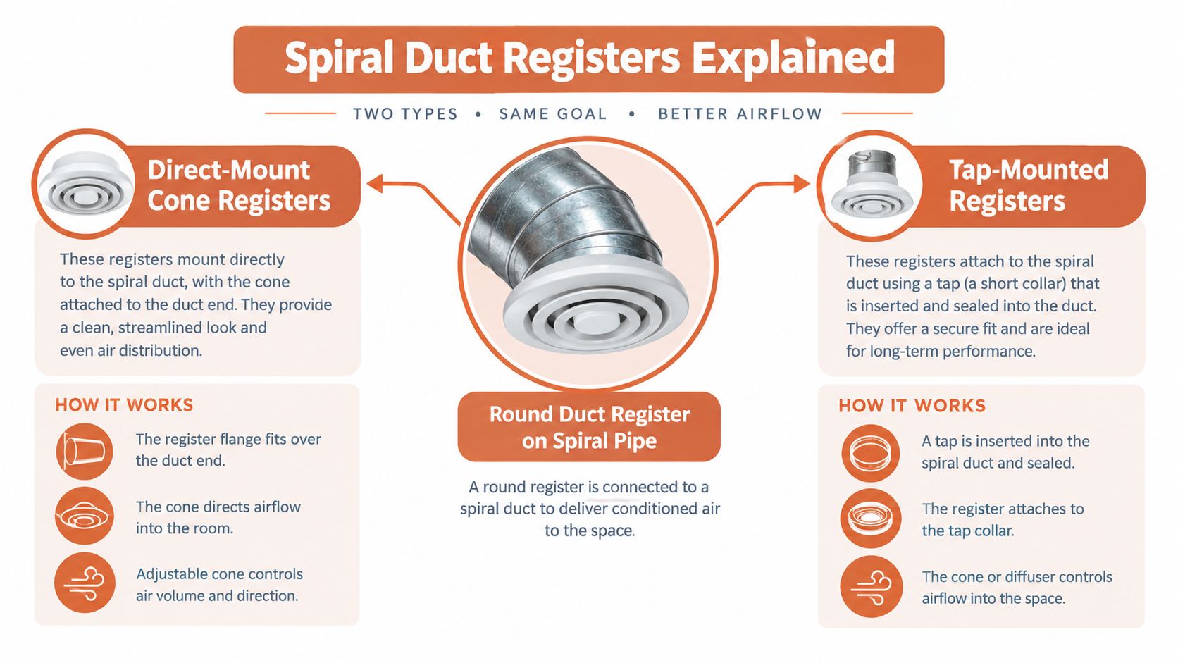
A spiral register and a rectangular diffuser may serve the same room, yet their connection geometries differ and their published throw and pressure-drop values are measured on different mounting arrangements. The same caution applies to generic round grilles: a catalog part only counts as a spiral duct register when it is engineered for the specified duct connection and operating conditions.
Why the round-duct standard matters
Spiral duct fabrication sits inside a long-standing sheet-metal standards framework. SMACNA's duct construction standards have governed this work for decades, and the industrial duct standard carries a dedicated spiral-duct chapter covering Classes 1 and 2 air systems. That framework matters on plan day because dimensional tolerances, leakage limits, fitting construction, and pressure class all define the conditions a register's performance data assumes. When a submittal lists throw and pressure drop, those figures trace back to a duct built to that standard.
For procurement, write descriptions that separate direct-mount from tap-mounted configurations and state the duct diameter and design conditions alongside the face size. A clear spec keeps engineers, installers, and buyers from treating a nominal dimension as a performance description. ATEK's heating, ventilation, and air-conditioning product category shows how suppliers organize these mounting configurations for project ordering.
Sizes, Materials, and Pressure Classes You Can Order
On plan day, a register that matches the spiral diameter can still land outside the operating envelope. Pressure class, material, temperature, reinforcement, and attachment method carry as much weight as the nominal connection size. A substitution that holds the face dimension while changing any one of those parameters needs technical review, not an automatic approval.
SMACNA construction guidance covers round long-seam and spiral duct from 4 inches through 60 inches in diameter, including reinforced and unreinforced construction. It addresses positive or negative pressures from 4 to 20 inches water gauge, with pressure classification driving material selection and reinforcement. The same guidance sets temperature limits by material (SMACNA construction guidance).
Spiral duct and register compatibility
| Parameter | Range | Notes |
|---|---|---|
| Duct diameter | 4 to 60 inches | The register's connection must match the scheduled spiral size and construction type. |
| Pressure | 4 to 20 inches water gauge, positive or negative | Establish the design pressure class first; diameter alone says nothing about suitability. |
| Carbon or stainless steel temperature | Ambient to 650°F | Check the register, gasket, and attachment ratings against the operating temperature. |
| Galvanized steel temperature | Up to 400°F | Don't assume a standard galvanized assembly is rated above its stated limit. |
| Aluminum temperature | Up to 120°F | Confirm material and temperature compatibility before specifying. |
The ordering takeaway is plain: a register chosen by neck or face size alone can end up fastened to duct running a pressure or temperature the assembly was never rated for. Negative pressure deserves the same scrutiny, because the register, gasket, and fastening method must suit the direction of flow along with the class.
A separate SMACNA industrial duct standard extends that envelope considerably, reaching deeper negative pressures, higher positive pressures, and spiral diameters well beyond the construction guidance above. Those figures describe the industrial standard's design scope, as the standards discussion earlier in this article established. They are not a rating for any register. Treat them as context for what the duct can be built to handle, then verify the register's own class and product documentation before assuming compatibility.
This matters downstream at TAB. The pressure class and material on the approved submittal are what the balancing technician compares against measured static pressure and throw at the scheduled CFM. If the installed register differs in class or construction from what was submitted, the catalog pressure-drop figures stop applying, and the balancing report loses its baseline.
Matching a Register to Your Duct Before You Cut the Opening
Before ordering or cutting, compare the schedule and submittal line by line. A catalog entry that appears to match the face dimension can still omit the pressure class, duct material, or airflow conditions needed to judge compatibility.
Review the connection and design conditions
Start by confirming the duct diameter at the exact register location, not just the main-run size. Check whether the terminal is direct-mounted or tap-mounted, and make sure the submittal describes the connection arrangement shown on the drawings. If the opening dimensions or fitting geometry aren't clear, resolve them before fabrication.
Next, identify the pressure class and operating environment from the project documents. Verify that the register assembly, gasket, and attachment method are suitable for the material, pressure direction, and temperature conditions. Don't infer a pressure rating from the product's face size or appearance.
Then review the performance information. Confirm scheduled CFM, airflow direction, discharge pattern, and the throw criterion used in the design. Ask whether the published data apply to the mounting arrangement and operating conditions on the job. Where information is absent or ambiguous, request clarification rather than treating the closest catalog option as equivalent.
Catch the mismatch before field work
The most common review gap is accepting a catalog match on face size without checking pressure class or material. Flag that gap in the submittal comments and require the supplier or manufacturer to document compatibility with the schedule. That simple review can prevent a cutout that leaves the installer trying to adapt a terminal that doesn't fit the duct or design.
For maintenance teams evaluating existing duct conditions before a repair or modification, this overview of signs your ductwork needs attention offers useful context. On a new installation, keep the focus on project-specific documents: the approved schedule, duct construction details, register data, and any required gasket or attachment information.
Installing the Register Without Leaking or Misaligning
Direct-mount registers can reduce transition hardware by eliminating a rectangular tap, but the advantage depends on a properly prepared opening. A distorted or inaccurately aligned cutout can leave gaps at the duct wall or prevent the register flanges from seating evenly.
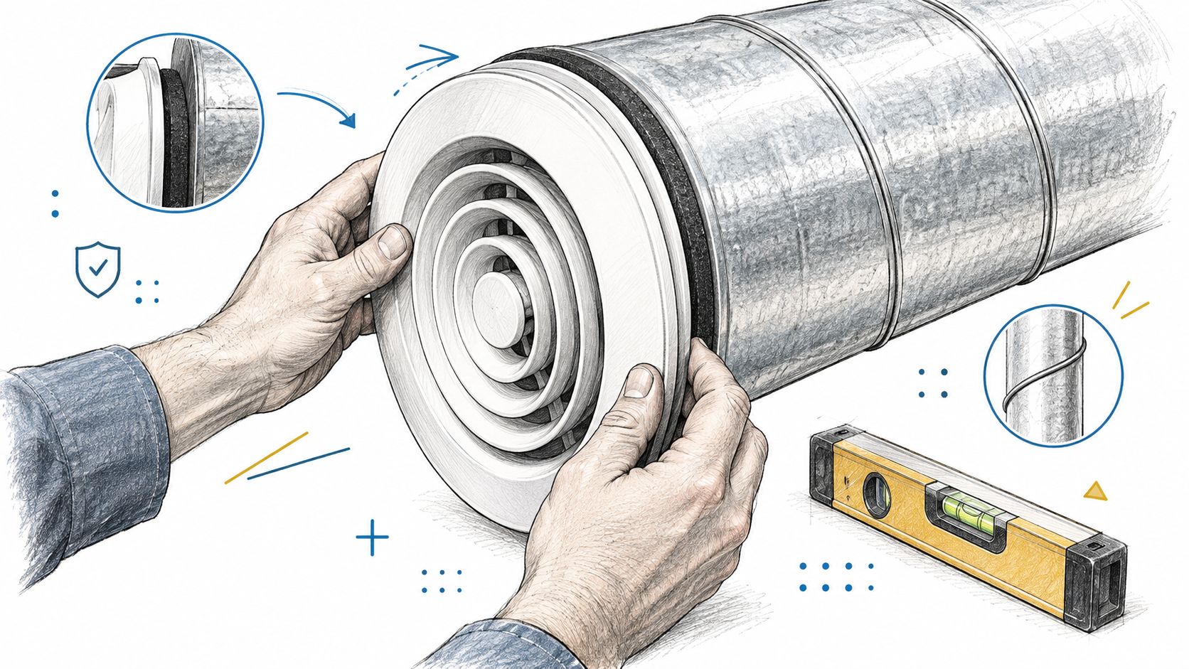
Inspect the opening for burrs, distortion, and edges that could interfere with the gasket or register. Remove debris and confirm the opening follows the approved dimensions. A rough edge or an uneven cut can compromise the connection even when the register itself is correctly sized.
Seat a continuous gasket against the duct wall, then fit the assembly so the upper and lower flanges sit flush. Secure it mechanically as specified for the product and installation. Check that fasteners hold the register evenly without pulling one side away from the duct. Before the ceiling or wall closes, inspect the full interface for visible gaps or movement.
Check the discharge orientation
Set extractors or adjustable vanes to the intended discharge pattern. Their orientation should follow the approved design, not an installer's assumption based on how the register looks from the floor. Record any field adjustment that changes the approved setup, so the TAB technician can test the actual configuration.
A direct-mount installation removes a transition, but it doesn't remove the need to inspect the airflow path. Confirm that nearby structure, insulation, or other services won't obstruct the outlet or make the intended pattern impossible. A short visual check before close-up can catch misalignment while the connection is still accessible.
The following installation video provides a visual reference for the assembly sequence:
Verifying Airflow, Throw, and Pressure Drop After Install
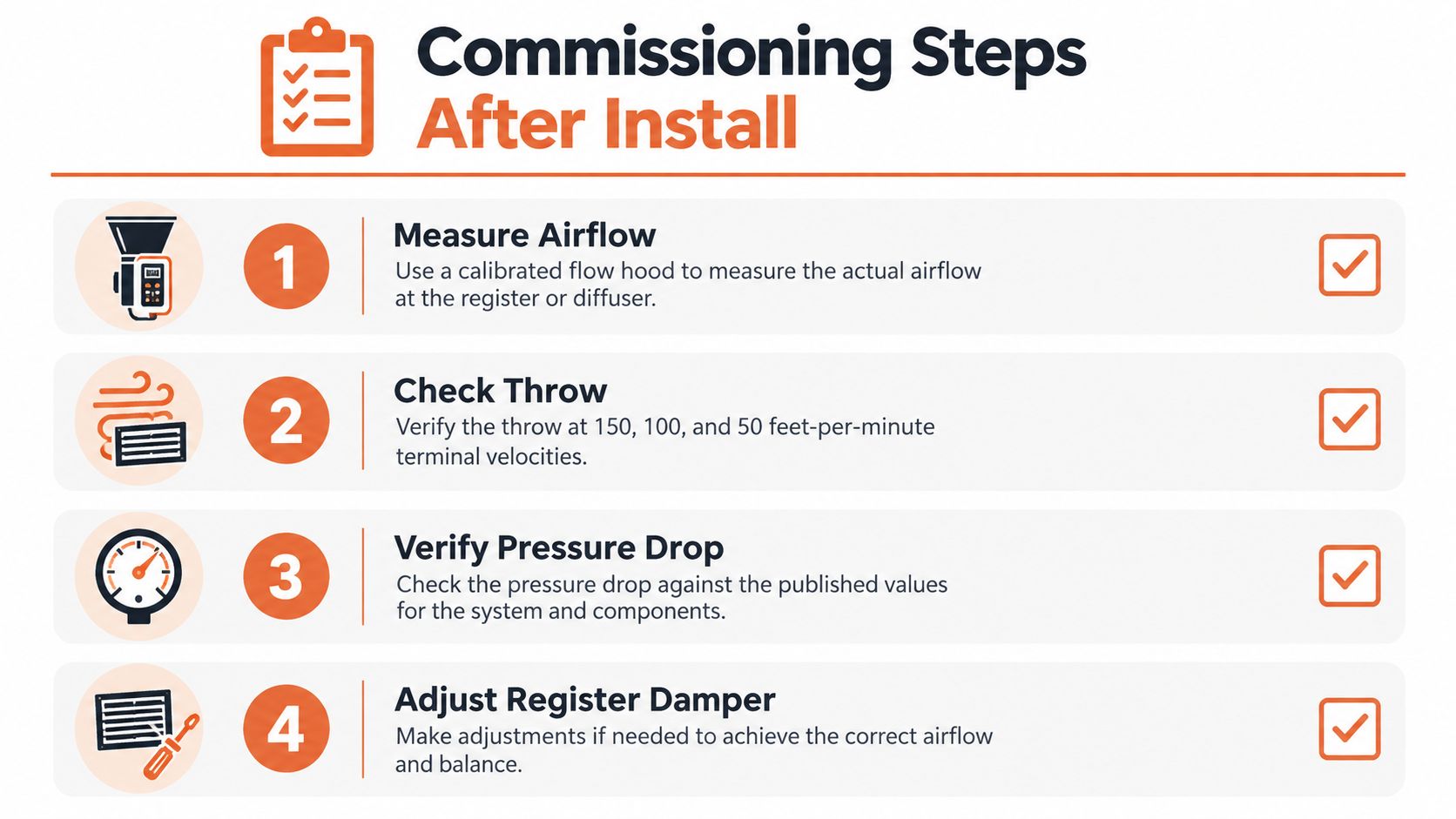
A register isn't commissioned when it's fastened in place. Verify the installed airflow after filters, dampers, grilles, and air-handler components are in position. A calibrated flow hood can measure terminal airflow under installed conditions; compare the reading with scheduled design CFM and record the result.
A practical acceptance benchmark is airflow within ±10% of scheduled design, as described in the RESNET verification reference (RESNET HVAC component verification). Some residential verification protocols permit the greater of ±20% or 25 CFM. Use the criterion required by the project or applicable verification protocol, and don't treat one benchmark as a universal replacement for the contract documents.
Read throw data in context
Published performance data for direct duct-mounted spiral grilles reports throw at terminal velocities of 150, 100, and 50 feet per minute under isothermal conditions (Nailor spiral grille performance data). These values describe progressively weaker air movement as the jet travels into the served space. Match the chosen throw to room geometry, mounting height, airflow volume, and acceptable drafts.
Isothermal data doesn't automatically describe heating or cooling operation. Temperature differences introduce buoyancy effects, so the actual discharge path may differ from catalog conditions. Adjustable-blade angle also changes effective outlet area and pressure-loss behavior. After adjusting vanes or register controls, measure airflow again instead of assuming a catalog curve predicts the installed result.
Pressure and airflow belong in the same TAB record. The ASHRAE Duct Fitting Database includes resistance information for more than 200 spiral, rectangular, and flat-oval fittings, supporting pressure-drop calculations for specified fitting sizes and airflow conditions (ASHRAE acoustics and duct-fitting research). Document measured CFM, static pressure, register setting, and any balancing adjustment. For a plain-language refresher on how system resistance affects design and testing, consult this static pressure guide for HVAC systems.
Acoustic, Cleanability, and IAQ Trade-Offs in Sensitive Spaces
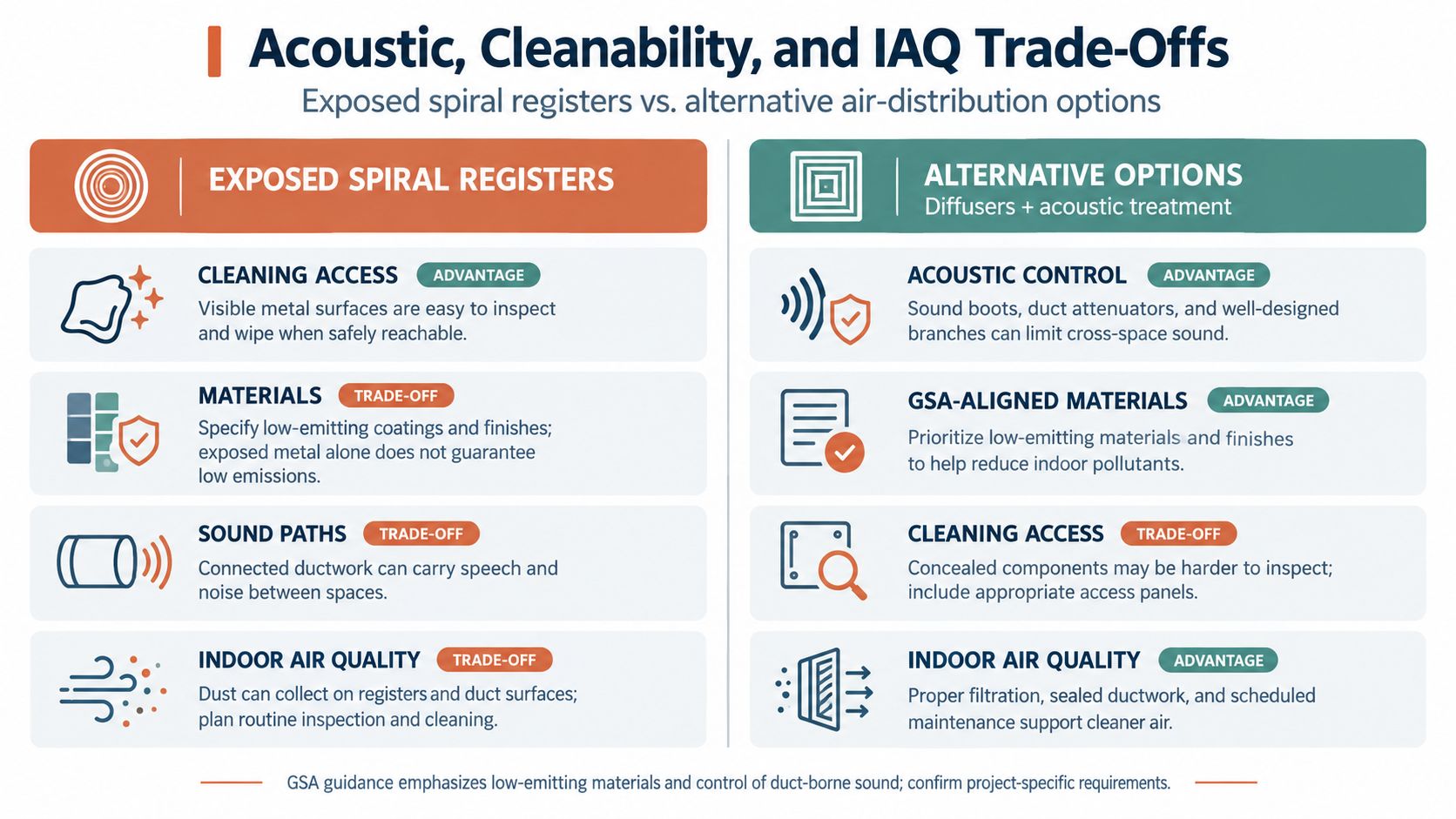
A classroom sits directly under an exposed spiral run, and the register that looked cleanest on the reflected ceiling plan is also the shortest sound path between the fan and thirty students. Exposed spiral duct with a simple metal register can suit a space visually while performing poorly on sound, hygiene, or maintenance. Ductwork transmits sound between rooms, and an outlet becomes a noticeable sound path when fan noise or high-velocity airflow reaches an occupied area.
The U.S. General Services Administration advises specifying quiet HVAC systems and limiting small, high-velocity ductwork where noise could produce unacceptable conditions and costly remediation. The acoustics and duct-fitting research cited earlier also measured transmission loss rising steeply with frequency in galvanized spiral steel duct, with enough spread between constructions that catalog values cannot predict what a given outlet will sound like in a finished room. Frequency, geometry, surface construction, and airflow resistance all matter. Treat published attenuation figures as evidence of that, never as a guarantee of installed performance.
Choose the configuration for the room
For classrooms, healthcare spaces, laboratories, and food-production environments, weigh occupancy, noise, cleaning access, condensation control, and hygiene requirements together before approving the submittal. A terminal box or silencer may be warranted when the design needs more acoustic control or a different connection arrangement. Internal acoustic lining can reduce sound along the run, provided it tolerates the facility's cleaning and contamination-control program. If the lining cannot survive the cleaning method or traps moisture, the acoustic gain turns into a maintenance and IAQ liability. Check whether the submittal specifies lined or unlined duct upstream of the register, because that one line item changes both the sound path and the cleaning procedure.
Spiral systems can be engineered for low leakage, though that answers only part of the selection question. Industry guidance reports properly engineered spiral duct leakage below 1%, while also identifying leakage as a concern for wasted energy and indoor air quality (ACHR News guidance on spiral duct). Leakage performance says nothing about whether an exposed register is quiet enough, cleanable enough, or appropriate for a sensitive space.
Coordinate rated penetrations and maintenance
Where ductwork crosses rated assemblies, coordinate the register location and duct route with required fire and smoke protection. UL states that fire dampers are tested as part of fire-resistance-rated vertical or horizontal assemblies under UL 555, while smoke dampers and combination products are evaluated under UL 555S and related standards (UL fire damper guidance). The required protection depends on the assembly and applicable project codes. A damper where none is required still adds static pressure and a maintenance point, so confirm placement rather than blanketing every register, and obtain listing and installation documentation before approving a substitution.
Keep the maintenance record tied to the installation. Remove registers as appropriate for the facility's cleaning program, inspect gaskets and connections, and file the approved submittal, installation photos, and TAB results together. That record lets the next technician distinguish a changed setting or damaged connection from a design issue, and it closes the loop between what was submitted and what was measured.
For a project with hard-to-source register sizes or submittals that need review against duct and operating conditions, contact ATEK Distribution. ATEK can assist with sourcing, manufacturer coordination, approved alternatives, and procurement documentation to help keep HVAC and electrical project requirements aligned.