Mega Lugs for PVC: Selection and Installation Guide

You're looking for “mega lugs for PVC,” but the first question isn't the pipe size. It's which PVC system you're working on. In water and wastewater construction, MEGALUG usually means a mechanical-joint restraint for PVC pressure pipe. In electrical work, PVC usually means conduit, and the required fittings are couplings, connectors, bodies, sweeps, adapters, or bushings. Those are different product categories with different installation methods.

That distinction matters before anyone orders material. A restraint gland for a mechanical-joint bell won't replace an electrical conduit fitting, and an electrical conduit accessory won't restrain a pressurized water main. The guide below focuses on EBAA Iron MEGALUG mechanical-joint restraint for PVC pressure pipe, including product families, pipe standards, sizing, gasket selection, torque, and field installation.

Table of Contents

What Mega Lugs for PVC Actually Are

MEGALUG is a registered EBAA Iron product family, not a generic name for every PVC lug or a fitting used with electrical conduit. The product is a mechanical-joint restraint gland designed for PVC pressure pipe used with compatible mechanical-joint bells. EBAA Iron's documentation identifies the Series 2000PV for C900, C905, and IPS OD PVC pipe, with product sizes extending from 3 inches through 36 inches and larger-diameter versions reaching 42 inches and 48 inches in the broader product family (Series 2000PV PVC MEGALUG specifications).

The fitting has a segmented gland ring, gripping wedges, and side bolts that engage the mechanical-joint flange bolt circle. Once assembled correctly, the wedges grip the pipe while the gland transfers axial force into the joint hardware. The restraint therefore addresses pipe movement at a joint, rather than sealing the joint against leakage.

The two PVC meanings buyers commonly mix up

A waterworks buyer is usually searching for restraint on:

  • AWWA C900 PVC pressure pipe
  • AWWA C905 PVC pressure pipe
  • IPS OD PVC pressure pipe
  • Compatible mechanical-joint fittings and appurtenances

An electrical contractor may instead be searching for a fitting for PVC conduit, cable routing, or a duct bank. That work uses conduit-specific components, not a pressure-pipe restraint gland. Mechanical-joint restraint also isn't a method for pulling wire through conduit or joining cement-welded conduit sections.

In practical terms, MEGALUG can reduce dependence on concrete thrust blocks where the design permits restrained joints. That can help on congested easements, inside casings, or in soils where excavation and bearing conditions complicate a conventional block. It doesn't eliminate engineering review. The pipe standard, outside diameter, bell dimensions, gasket, joint configuration, and installation instructions still control.

Practical rule: Start with the pipe print line and joint type. Don't start with the word “PVC” in a search box.

The remaining selection process is straightforward. Identify the pipe standard, verify the outside diameter, choose the matching Series 2000PV family, then confirm gasket and torque requirements before assembly.

The MEGALUG Product Families at a Glance

The Series 2000PV family scales with the pipe, but it isn't one universal gland that fits every PVC dimension. The key procurement mistake is treating nominal size as sufficient. Nominal size only becomes useful after it's matched to the pipe's outside-diameter basis and mechanical-joint configuration.

The published product information supports a range from 3 inches through 36 inches, with larger installations extending to 42 inches and 48 inches (EBAA Iron Series 2000PV product information). The broad selection logic looks like this:

Family Nominal Size Range Pipe Standards Bolt Size
Series 2000PV, smaller sizes 3 to 12 inches C900, C905, and IPS OD PVC where specified Published product data identifies smaller restraint hardware, including 3/4-inch T-bolts
Series 2000PV, mid-range sizes 14 to 36 inches Primarily larger-diameter C905 and compatible AWWA PVC applications Published product data identifies larger hardware, including 1-inch bolts in the mid-range
Mega Series, large diameter 42 to 48 inches Large-diameter C905 PVC applications Heavier hardware, with published torque ranges of 120 to 150 ft-lbs for these sizes (PVC MEGALUG data sheet)

The smaller range is where C900 and IPS OD PVC commonly overlap in nominal size. That overlap doesn't mean the pipes have identical dimensions. The gland body may be selected by nominal size, while the gasket and pipe OD determine whether the assembly is compatible.

The 14- to 36-inch range addresses larger PVC pressure pipe, particularly C905 dimensions that follow a ductile-iron-pipe-equivalent outside diameter. The 42- and 48-inch versions are intended for major transmission applications and require closer attention to hardware, torque, joint design, and field access.

Treat the product family as a system of matched components. The bell, gland, bolts, wedges, gasket, pipe OD, and installation procedure must agree. A correct nominal size paired with the wrong OD basis is still a wrong selection.

Pipe Standards MEGALUG Is Designed For

The pipe standard tells you more than the material. It also points to the dimensional system that the restraint must grip. For PVC pressure pipe, the important distinction is between C900, C905, and IPS OD dimensions.

Nominal Size Pipe Standard OD Basis MEGALUG Family
4 to 12 inches AWWA C900 PVC C900 outside diameter Series 2000PV smaller sizes
4 to 12 inches IPS OD PVC Iron-pipe-size outside diameter Series 2000PV IPS-compatible selection
14 to 48 inches AWWA C905 PVC Larger-diameter AWWA PVC, commonly aligned with ductile-iron-equivalent joint dimensions Series 2000PV mid-range or large-diameter Mega Series
Matching mechanical-joint fittings Ductile iron Mechanical-joint bell dimensions Compatible restraint selected for the actual pipe and joint

The transition between 12 inches and 14 inches deserves special attention. C900 and C905 aren't interchangeable dimensionally because both are PVC pressure-pipe standards. An IPS OD pipe in that area also shouldn't be assumed to match a restraint designed around a ductile-iron-equivalent outside diameter.

A MEGALUG must grip the actual spigot OD, and the bell must accept the selected joint hardware. The product documentation identifies compatibility with C900, C905, and IPS OD PVC, but the specific catalog size and gasket still need to match the pipe on the project (Series 2000PV PVC restraint documentation).

For electrical projects, use conduit-specific catalog categories instead. ATEK's PVC electrical conduit fittings cover the type of couplings, connectors, elbows, adapters, reducers, and bushings used to build conduit systems. Those products serve a different installation purpose and shouldn't be substituted for pressure-pipe restraint.

Sizing a MEGALUG to Your PVC Pipe

Order from the pipe, not from memory and not only from the purchase order. The installer should confirm three items before selecting a gland:

  1. Nominal pipe size
  2. Outside diameter at the spigot
  3. Pipe standard printed on the barrel

The print line is especially valuable because C900, C905, and IPS OD PVC can share nominal sizes while using different dimensional conventions. A tape measure helps verify the physical pipe, but it doesn't replace the standard, DR, or manufacturer identification.

A practical field check

Clean the area where the gland will seat, then inspect the pipe for gouges, raised material, dirt, or damage that could interfere with the wedges or gasket. Measure the barrel OD where the restraint will engage, rather than measuring a bell, coupling, or protective coating.

Nominal Size (in) Pipe Standard Series 2000PV Size Note
3 to 12 C900 or compatible PVC selection Matching nominal Series 2000PV size Confirm the exact OD and product listing
4 to 12 IPS OD PVC Matching nominal Series 2000PV IPS selection Transition gasket may be required
14 to 36 C905 PVC Matching Series 2000PV size Confirm C905 dimension and joint configuration
42 to 48 Large-diameter C905 PVC Matching Mega Series size Confirm large-diameter hardware and torque

Consider two nominally similar examples. An 8-inch DR18 C900 main maps to an 8-inch Series 2000PV restraint selected for the C900 dimension. An 8-inch IPS OD PVC service line may use the same nominal body size, but it requires the IPS-specific transition-gasket arrangement identified by the manufacturer.

That's why the size printed on the order isn't enough. The pipe that arrives on the truck controls the final check.

Gaskets, Torque, and Mechanical-Joint Assembly

Gasket selection comes before torque. A properly torqued gland with the wrong gasket is still an incorrect assembly. Standard MEGALUG arrangements use a standard SBR gasket for compatible C900 and C905 PVC applications, while IPS OD PVC requires a transition gasket because its outside diameter differs from the cast-iron-equivalent dimension.
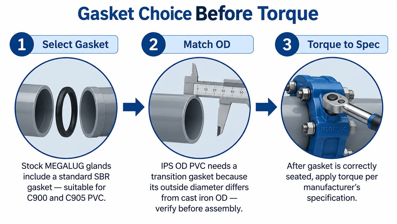
A three-step technical guide for selecting and installing the correct gasket for MegaLug pipe joints.

Assemble the joint in the right order

  • Clean the socket: Remove soil, debris, old gasket material, and anything that can prevent the gasket from seating.
  • Choose the gasket: Use the standard gasket for the listed compatible PVC dimension. Use the transition gasket for IPS plastic pipe where the instructions require it.
  • Seat the gasket: Place it evenly in the bell recess. A twisted or partially seated gasket can create leakage or interfere with insertion.
  • Insert the spigot: Bring the pipe into the bell to the required insertion mark or assembly position.
  • Position the gland: Slide the gland over the pipe and align it with the mechanical-joint flange.
  • Start the bolts: Hand-start the T-bolts and ensure the hardware engages without cross-threading.
  • Torque in a star pattern: Tighten progressively and evenly so the gland seats uniformly around the pipe.

For the large 42-inch and 48-inch installations, the published torque range is 120 to 150 ft-lbs (PVC MEGALUG installation data). Smaller sizes use lower torque values specified by the applicable product data. Use a calibrated torque wrench and follow the manufacturer's sequence rather than applying the large-diameter value across the entire range.

Field caution: Never treat an IPS gland, cast-iron-dimension bell, and standard gasket as interchangeable parts. The joint has to be specified as a complete assembly.

The most common failure is skipping the transition gasket on IPS PVC. Another is mixing an IPS restraint with a bell intended for a different OD basis. The joint might hold during an initial pressure check, yet still lack the intended behavior under deflection or axial loading.

For project hardware and related requirements, procurement teams can also review ATEK's fasteners and hardware category. The restraint itself must still be selected and installed from the applicable MEGALUG documentation.

Thrust Restraint Versus Thrust Blocks

A thrust block and a mechanical restraint solve the same broad problem, but they rely on different mechanisms. A concrete thrust block transfers fitting thrust into the surrounding soil through a bearing face. Its performance depends on the block geometry, concrete placement, soil bearing conditions, and available excavation space.

A MEGALUG transfers axial force through the gland, wedges, pipe wall, bolts, and mechanical-joint bell. The manufacturer's documentation describes restraint performance testing to ASTM F1674, use with AWWA C600 and AWWA D2774, FM approval for applicable fire-protection service, and full-deflection capability (EBAA Iron Series 2000PV documentation).

Factor MEGALUG Restraint Thrust Block
Load path Gland and joint hardware transfer axial force through the pipe system Concrete transfers force into surrounding soil
Soil dependence Less dependent on a concrete bearing face Strongly dependent on soil bearing and block placement
Excavation Can suit congested alignments and constrained tie-ins May require room for block excavation and placement
Installation timing Doesn't depend on concrete cure time Requires concrete placement and adequate curing
Deflection Manufacturer documentation addresses full-deflection performance A block doesn't itself create a restrained, deflectable joint
Design responsibility Must match pipe, bell, gasket, and restraint Must match fitting thrust, soil, and block design

This isn't an argument that thrust blocks are always wrong. They remain a valid design method where soil conditions, geometry, access, and project specifications support them. The practical advantage of active restraint appears when a project has unstable or disturbed soil, limited easement width, a casing, or a retrofit tie-in that would require disruptive over-excavation.

For new PVC mains, the decision should come from the engineer's restraint design and the manufacturer's compatible product data. For difficult tie-ins, mechanical restraint often gives the crew a more controllable installation than trying to create a reliable concrete bearing surface in a crowded excavation. Teams handling larger infrastructure scopes can also use design-build engineering services for infrastructure when the procurement package needs technical coordination.

Compatibility Nuances by Pipe Class and Diameter

Pipe class and DR affect wall thickness, pressure capability, and how the gasket and gripping components interact with the spigot. A restraint selected by nominal size alone can miss those details. For C900, common DR designations include DR14, DR18, and DR25. C905 documentation can include DR14, DR18, DR21, DR25, DR32.5, and DR41. The applicable MEGALUG body and installation instructions still need to be checked against the actual pipe and joint.

PVC Class DR Ratio Size Range (in) Matching Series 2000PV Service Note
C900 DR14, DR18, DR25 4 to 12 Smaller Series 2000PV selection Confirm C900 OD and pressure-pipe application
C905 DR14, DR18, DR21, DR25, DR32.5, DR41 14 to 48 Mid-range Series 2000PV or large-diameter Mega Series Confirm the C905 size and joint dimensions
IPS OD PVC Project-specific DR or dimension Commonly 4 to 12 IPS-compatible Series 2000PV selection Transition gasket required where specified
PVC appurtenance connection Matching listed pipe dimension Project-specific Restraint selected for the connection Confirm whether the joint is under continuous pressure service

Wall thickness changes the fit, not the basic selection logic

A thinner-wall pipe can present a different seating condition than a thicker-wall pipe of the same nominal size. The gland must fully seat, the wedges must engage without damaging the pipe, and the gasket must remain correctly positioned. Don't compensate for an uncertain fit by increasing torque. Excessive or uneven tightening can damage the assembly rather than improve restraint.

Pressure service deserves the most conservative review because the joint sees operating pressure, transient loads, and axial thrust over its service life. Appurtenance-only restraint may have a different role, but it still requires a compatible listed configuration. The product isn't automatically suitable for every fitting, repair, or transition.

The same selection discipline applies at the upper end. The standard Series 2000PV range ends at 36 inches, while larger installations extend to 42 inches and 48 inches through the Mega Series product family (PVC MEGALUG specifications). That change in diameter brings heavier hardware, different torque requirements, and a greater need for planned access around the joint.

What Mega Lugs Are Not Used For

MEGALUG isn't an electrical PVC conduit fitting. It isn't a cable-tray support, a conduit body, a sweep, or a cement-welded coupling. It also isn't a repair coupling for cracked pipe, and it shouldn't be applied to an HDPE fusion joint without a specifically engineered transition.

Some buyers search for EB-35 or DB-120 duct-bank categories while using “mega lug” as a broad term for PVC infrastructure hardware. That search path can lead to the wrong catalog entirely. Electrical conduit systems need fittings designed for conduit dimensions, pull access, bonding or grounding requirements where applicable, and the installation method specified for that raceway system.

A mechanical-joint restraint on a pressure pipe doesn't become conduit hardware because both products involve PVC.

If the job involves wire pulling, conduit bodies, sweeps, threaded adapters, cement-welded couplings, or duct-bank assembly, source from an electrical PVC conduit catalog. Don't attempt to route cable through a pressure-pipe restraint or treat the gland as a code-recognized conduit connection. The words “PVC” and “lug” overlap in search results, but the engineering functions don't.

Quick Reference Card for Selection and Torque

Use this card as a procurement checkpoint, not as a substitute for the manufacturer's installation sheet or the project engineer's approved submittal.

Series Size (in) PVC Standard Gasket Torque (ft-lbs)
Series 2000PV 3 to 12 C900 or compatible IPS OD PVC Standard gasket for listed C900 applications, transition gasket for IPS where specified Use the published value for the selected size
Series 2000PV 14 to 36 C905 Standard gasket for the listed application Use the published value for the selected size
Mega Series 42 to 48 Large-diameter C905 Gasket specified for the listed assembly 120 to 150, per published PVC data

Before placing the order, confirm the nominal size, pipe standard, outside diameter, bell type, gasket, and bolt hardware. For IPS plastic pipe, verify the transition gasket requirement. For large-diameter installations, plan access for the heavier hardware and use the specified torque range.

Torque values assume a clean, properly seated assembly. A torque wrench can't correct a twisted gasket, contaminated socket, damaged spigot, or mismatched gland.

Frequently Asked Questions About MEGALUG on PVC

Does full deflection mean the joint can move freely? No. It means the listed restrained assembly is designed to accommodate the manufacturer's published deflection without joint separation when installed correctly.

When does IPS PVC need a transition gasket? IPS OD PVC requires the transition gasket where the manufacturer's instructions identify the outside-diameter difference from the cast-iron-equivalent joint dimension.

Are MEGALUG restraints useful for retrofit tie-ins? They can be practical where a thrust block would require excessive excavation, provided the pipe, bell, gasket, and service conditions are compatible.

What documentation should procurement request? Request the applicable submittal sheet, installation instructions, restraint-performance documentation, FM approval information where relevant, and AWWA installation references.


ATEK Distribution can help source compatible PVC conduit fittings, fasteners, hardware, and project documentation when your scope includes both electrical and infrastructure work. Confirm the pipe standard and restraint requirements first, then visit ATEK Distribution to request product sourcing or technical procurement support.
Cable Ferrule Crimp Guide for Clean Terminations

You've just stripped a flexible conductor for a control panel terminal. The copper strands fan out, one slips under the clamp, and the finished connection looks acceptable until vibration or repeated heating exposes the weakness. A proper cable ferrule crimp prevents that failure by forming the strands into a controlled termination that the terminal can clamp consistently.

Appearance is only the first check. A reliable termination depends on the conductor, ferrule, die profile, crimp position, tool condition, and verification method working together. The useful question isn't whether the sleeve looks compressed. It's whether the connection matches the applicable requirements and withstands the pull force expected for its conductor size.

Table of Contents

Why Cable Ferrules Exist and When They Apply

A stranded conductor can fail at the terminal even when the insulation and copper look undamaged. Individual strands may spread under a screw or spring clamp, creating uneven pressure and leaving the connection vulnerable to movement and oxidation. A ferrule holds the strands in a metal sleeve, presenting the terminal with a defined contact area rather than a loose bundle.

Ferrules entered widespread European practice in the latter half of the twentieth century as manufacturers sought to protect stranded copper conductors at terminal screws. That purpose remains practical: the sleeve controls the conductor mechanically before the terminal applies clamping force. The relevant practice is reflected in the DIN 46228 series, along with EN 60999-1 and EN 60352-2, as outlined in Phoenix Contact's standards guidance.

Match the conductor before choosing the sleeve

Select the ferrule from the conductor's cross-section, not from color alone. Insulated ferrules use standardized dimensions and color identification under DIN 46228-1. Ferrules intended for fine-stranded conductors require the tighter dimensional considerations associated with DIN 46228-4. The sleeve should accept the entire strand bundle without folding strands, shaving copper, or leaving empty space inside the barrel.

Conductor construction also affects the termination. Fine-stranded cable contains more individual strands, so insertion and compression need closer control. A tinned end presents another condition because solder can stiffen the conductor near the clamp. Treat it differently from clean, flexible copper prepared for a ferrule.

Practical rule: Use a ferrule when a stranded conductor enters a screw or spring terminal rated to accept ferrules, especially in control, instrumentation, safety-related, or vibration-exposed work. Confirm the terminal manufacturer's instructions before making the method standard.

Ferrule families commonly cover conductor cross-sections from 0.5 to 50 mm², roughly AWG 20 to 1/0. The range describes the product family, not the capacity of one crimp tool. Check the ferrule and die ratings against the actual conductor size, then verify the finished termination with the applicable pull-force requirement. A sleeve that fits physically can still be the wrong choice if its dimensions, conductor class, or crimp profile do not match the terminal and tool.

Choosing a Ferrule Crimp Tool for the Job

The tool profile determines how the sleeve deforms, how evenly it compresses the strands, and how well the finished end fits the terminal. Three families cover most panel and harness work: square-profile ratcheting tools, trapezoidal-profile tools, and four-indent pneumatic or heavy-duty ratcheting crimpers.

A square-profile ratcheting tool is the practical daily choice for many control-panel benches. It's quick, relatively affordable, and the completed ferrule has flat sides that seat neatly in many spring and screw terminals. Its limitation is coverage. A die window may handle a useful group of conductor sizes, but it won't automatically make the tool suitable for every ferrule in the drawer.

Trapezoidal-profile tools produce a compact, repeatable deformation favored in many European panel-building environments. They can give a clean termination that inserts smoothly into spring terminals, but the tool and ferrule still need to be matched. A neat shape doesn't compensate for a die that's outside its rated range.

Four-indent tools compress the sleeve from multiple directions and can produce a strong, near-round termination for fine-stranded cable and demanding harness work. They cost substantially more than everyday hand tools, so the investment makes sense where the work involves production volume, fine-stranded conductors, or documented pull-force requirements. For occasional panel repairs, their capability may be unnecessary.

Tool family Typical AWG / mm² range Crimp profile Relative cost Best fit for
Square-crimp ratcheting hand tool Depends on the marked die window Square Lower General control-panel wiring and service work
Trapezoidal-crimp ferrule tool Depends on the selected die Trapezoidal Moderate Repeatable European-style panel wiring and spring terminals
Four-indent pneumatic or ratcheting tool Depends on the ferrule and die set Four-indent, near-round Higher Fine-stranded cable, harness production, and documented quality programs

Check more than the profile. The important details are the rated conductor range, handle force at that range, die marking, ratchet completion, and calibration basis. A tool that merely says “automatic” or “self-adjusting” isn't automatically compliant with a particular ferrule standard. Look for documentation connecting the tool and ferrule system to the required dimensions and test method.

For sourcing, ATEK Distribution's tools and testing selection is one place to compare crimping and verification equipment alongside the rest of a project's electrical requirements. The tool still has to be selected against the conductor, ferrule, terminal, and acceptance procedure.

Preparing the Conductor and Ferrule

A pull test can expose a preparation error before the ferrule ever reaches the terminal. Measure strip length from the ferrule collar and barrel depth, then adjust the stripper so insulation finishes where the collar can support it. The copper should extend only slightly beyond the sleeve shoulder. Phoenix Contact's technical guidance limits conductor protrusion to no more than 1 mm in its validation workflow.

Use a sharp, correctly adjusted stripper. A nicked strand reduces the conductor's strength, even when the defect disappears inside the barrel. After stripping, trim fanned strands cleanly. Do not twist them tightly or push loose filaments back into position.

Build the fit in a controlled sequence

Match the ferrule to the conductor cross-section and the specified ferrule family. DIN 46228-1 assigns a color band to each cross-section, and adjacent sizes such as 1.0 mm² and 1.5 mm² can look alike in poor light. Select from a labeled strip magazine or tray, then confirm the printed size against the manufacturer's documentation. For two conductors, use a twin ferrule rated for that arrangement rather than forcing both wires into a standard sleeve.

Inspect the barrel before insertion. It must be clean, undamaged, and free of deformation. The conductor should enter straight until the insulation meets the inside of the collar. Keep the fit dry: lubricants and flux can affect the termination, while residue or visible oxidation can interfere with reliable contact.

A strand folded backward inside the barrel creates a hidden void or stress point that may reduce measured pull force. ATEK Distribution's wire and cable range can help source the conductor alongside the ferrule specification when the materials need to remain under one controlled purchasing process.

Crimping the Ferrule End to End

Insert the prepared conductor fully into the sleeve. Check the collar first. The insulation should approach the collar without being trapped beneath the metal barrel, and no stray strand should escape at the entry. If the conductor doesn't slide in straight, stop and correct the strip or ferrule selection before applying pressure.

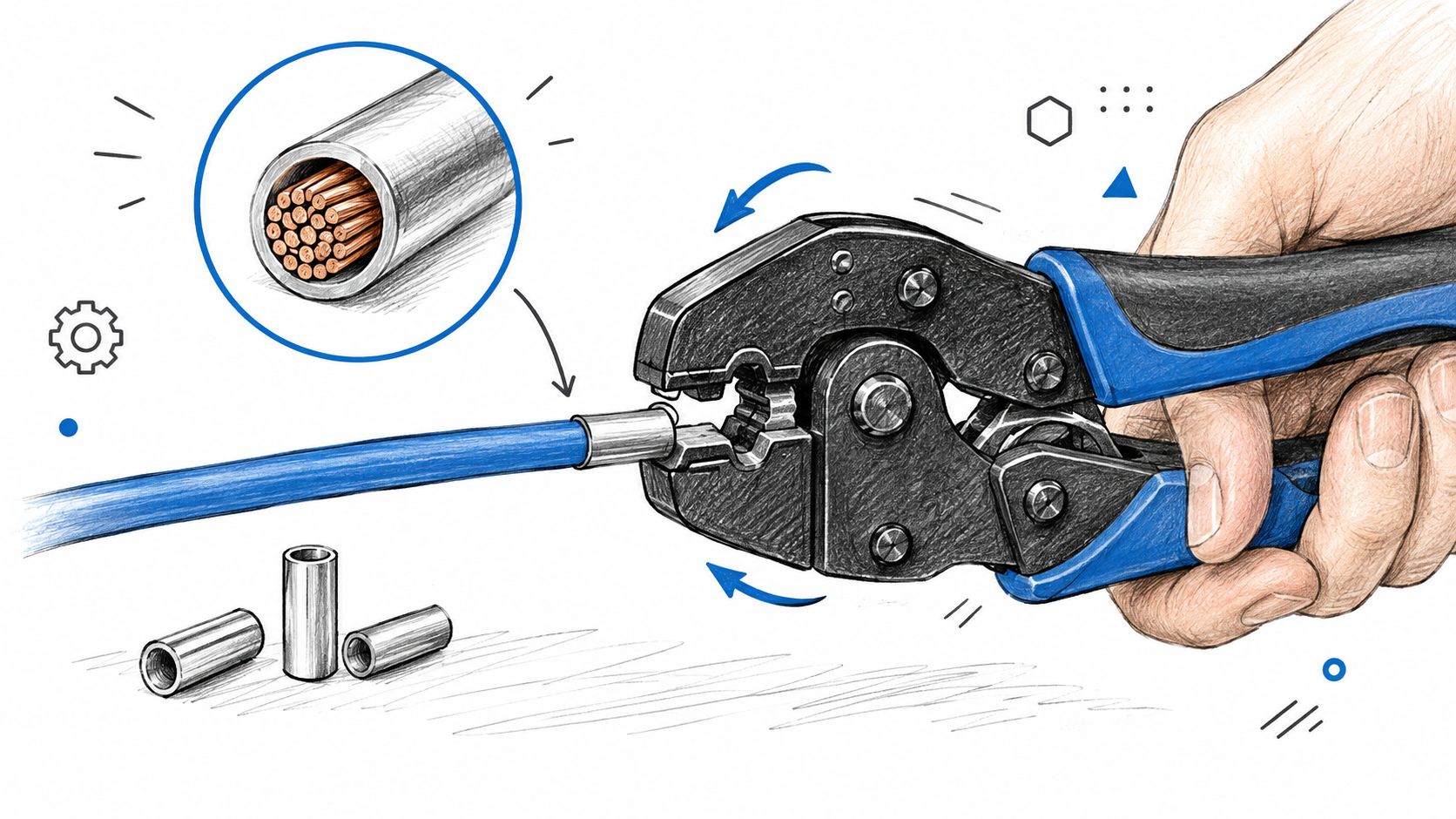
A hand using a specialized crimping tool to secure a metal ferrule onto the end of a blue electrical cable.

Place the ferrule in the die with the collar facing the correct direction and the sleeve centered in the rated crimp zone. The die should land close to the sleeve shoulder without crushing the plastic collar. Keep the crimp axis aligned with the conductor. A rotated or off-axis indentation can leave one side compressed while another side remains loose.

Close the tool through its complete cycle. With a ratcheting tool, don't reopen the handles halfway through and call the result finished. The ratchet exists to prevent partial compression, and the final release confirms that the designed stroke has been completed.

Control the compression across the sleeve

For larger sleeves or tools designed for multiple compression points, follow the manufacturer's sequence from the rear zone toward the front. The sleeve needs continuous support along its working length, not a single deep mark that leaves the rest of the barrel loose. Keep successive indentations in the same plane and re-square the ferrule before each compression when the tool requires repositioning.

A finished profile may be square, trapezoidal, or multi-indent depending on the tool. The profile should be even, with no fish-mouth opening, copper flash, split sleeve, or damaged collar. The wire should exit straight rather than bending sharply at the sleeve edge.

The Phoenix Contact crimping test guidance describes a validation approach in which the ferrule remains fixed under a target tensile load before the pull continues to failure. That is the standard to keep in mind while crimping. A clean shape is useful evidence, but it isn't the acceptance test.

A practical video demonstration can help operators see tool positioning and complete-stroke technique:

Inspecting the Crimp Against Pull Force

A pull test answers the question visual inspection can't. Does the conductor remain fixed in the ferrule under axial load, or does it slide before the connection reaches its expected strength? Standards-based ferrule practice ties quality to dimensions, tensile performance, and reliable contact formation, not to a crimp that merely looks symmetrical.

Published Weidmüller crimp tables provide these minimum pull-force values for selected conductor sizes: 10 N at 0.5 mm², 40 N at 1.5 mm², 60 N at 4 mm², 80 N at 6 mm², 100 N at 16 mm², 135 N at 25 mm², and 190 N at 35 mm². These values appear in Weidmüller's crimping documentation. Don't interpolate a value for an unlisted size and treat it as an approved requirement. Use the ferrule and tool manufacturer's table for the exact combination.

Conductor Size Minimum Pull Force (N) Typical Failure Mode Below Threshold
0.5 mm² 10 Conductor slips from an under-compressed sleeve
1.5 mm² 40 Strand bundle moves inside the ferrule
4 mm² 60 Partial compression or oversized die leaves a loose joint
6 mm² 80 Sleeve deformation doesn't retain the conductor
16 mm² 100 Incomplete compression or poor die match
25 mm² 135 Large-conductor sleeve slips or fractures at the exit
35 mm² 190 Insufficient full-length compression or tool mismatch

Run the test as a controlled check

Clamp the ferrule or its test fixture without damaging the sleeve. Apply axial force with a pull gauge or load cell, hold the target load for the specified duration, and then continue at the prescribed rate until failure. The technical workflow described by Phoenix Contact holds the target load for 60 seconds and then increases the pull speed to about 25 mm/min. A passing connection remains fixed at the target load, while the conductor shouldn't pull out before the intended failure condition.

Visual inspection still matters. Check that the collar is intact, the indentation is symmetric, insulation isn't trapped beneath the barrel, and no copper has been shaved or pushed outside the sleeve. A crimp that looks excellent but falls below the applicable pull-force requirement is scrap.

NASA ultrasonic inspection research also shows why production teams shouldn't rely on appearance alone. One NASA study detected under-crimped terminations at a 97% detection rate, 93 of 96 samples, with a 1% false-call rate, 1 of 96, when ultrasonic transmission exceeded a threshold amplitude. The NASA report also connects ultrasonic amplitude changes with destructive pull-test outcomes. For routine bench work, calibrated tooling and destructive sampling may be sufficient. For higher-volume production, ultrasonic verification can add a non-destructive quality control layer.

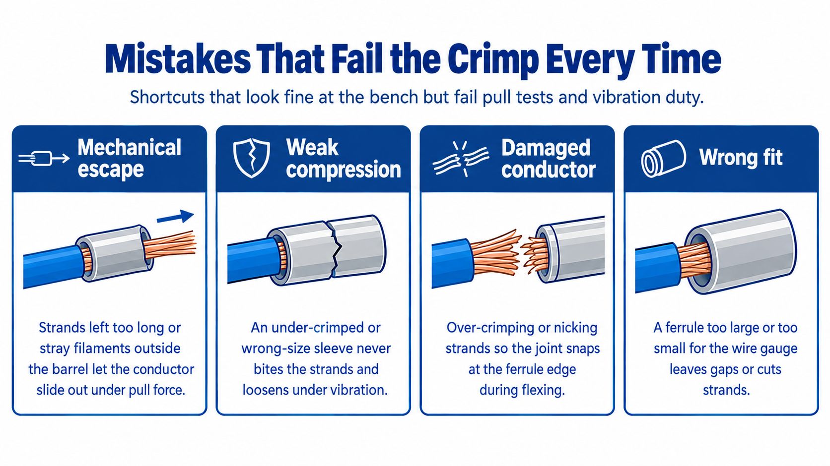
Mistakes That Fail the Crimp Every Time

The failures that cause trouble are usually small and repeatable. A wrong strip length, mismatched die, or incomplete tool stroke can produce a termination that passes a casual visual check while failing under pull or vibration.

An educational infographic illustrating four common crimping mistakes that lead to electrical connection failures.

Start with the mechanical escape paths

A short strip leaves a gap between the conductor end and the sleeve nose. That reduces the supported length and gives the strand bundle room to move. An excessively long strip exposes copper beyond the sleeve, which can interfere with terminal clearance and create an avoidable electrical hazard.

A mismatched die fails in two directions. An oversized die leaves the strands insufficiently compressed, while an undersized die can shave strands, crush the collar, or force copper out of the barrel. The correct die window is the one specified for the ferrule and conductor, not the closest opening that happens to accept the part.

Look for compression defects

Rotated indents, partial handle closure, and skipped compression zones leave gaps in the sleeve. Those gaps may allow movement and oxidation, increasing contact resistance over service life. A complete ratchet cycle and consistent die alignment remove much of that operator variation.

Tool condition matters just as much. Worn jaws, loose pivot pins, contamination in the die, or a ratchet mechanism that no longer completes its designed stroke can produce weak crimps even when the operator follows the sequence. Inspect the tool when a pull test fails. Replacing the ferrule without correcting the tool only repeats the defect.

Protect the conductor before it enters the sleeve

A dull stripper can nick strands. Insulation left under the barrel prevents the sleeve from gripping the intended copper length. Pre-tinned conductors bring solder creep and a rigid transition into a termination designed for flexible strands. Tinning isn't a substitute for a ferrule in a screw or spring terminal.

A two-wire shortcut isn't a standard termination. If two conductors need to enter one terminal, use a correctly specified twin ferrule and matching tool, or use an approved terminal arrangement.

A standard ferrule isn't a license to cram two wires into one sleeve. The barrel, collar, conductor combination, and tool must be designed for that configuration. If the terminal needs separate conductors, use separate ferrules or an approved bridging method. If the application calls for a ring, fork, or specialized connector, use that termination instead of forcing a ferrule into the wrong hardware.

When a Ferrule Is the Right Termination

The decision starts with the terminal, not the tool drawer. A ferrule is usually the right choice when a stranded conductor enters a screw or spring-clamp terminal rated for ferrules, especially where vibration, repeated service, or consistent insertion matters. The terminal manufacturer's instructions remain decisive because some terminals specify a particular ferrule profile, conductor class, or insertion length.

Ferrules are particularly useful for flexible control wiring and fine-stranded conductors because they contain the strands before clamping. They're also preferable to solder-tinning a stranded end. Tinning creates a rigid section that can fracture or deform under clamp pressure, while a correctly selected ferrule preserves a controlled mechanical termination.

Use the application as the decision filter

Do not add a ferrule automatically to every electrical connection. A ring or fork terminal is the proper choice for a stud or screw designed for that lug. A direct termination may be specified for a connector that doesn't accept ferrules. A PCB pigtail may need a connector or soldered joint designed for that board, not a ferrule selected from a panel-wiring kit.

Termination Method Best Application Standards Reference Key Limitation
Insulated ferrule Stranded conductor in an approved screw or spring terminal DIN 46228-1, EN 60999-1 Must match conductor size, terminal, and tool
Fine-stranded ferrule Flexible or fine-stranded conductor requiring controlled clamping DIN 46228-4, EN 60352-2 More sensitive to sleeve and tooling mismatch
Twin ferrule Two conductors entering a terminal approved for that arrangement Applicable ferrule and terminal manufacturer requirements Requires a correctly sized twin sleeve and die
Ring or fork terminal Stud, busbar, or screw connection designed for a lug Equipment and terminal requirements Not a substitute for a ferrule in a cage or spring terminal
Direct conductor termination Terminal specifically rated for the conductor without a sleeve Terminal manufacturer's instructions Strands can splay if the terminal isn't designed for them
Soldered pigtail Board or component connection designed for solder Product and assembly requirements Not a replacement for a ferrule under a clamping terminal

Standards guidance links ferrule quality to dimensions, test methods, and tensile performance. The Weidmüller ferrule reference is useful when translating that logic into a selection decision, but the equipment maker's terminal data should control the final choice.

For buyers, ATEK Distribution's wire termination and supplies can help consolidate ferrules, crimp tools, wire, and related termination products around a defined specification. Confirm the conductor cross-section, ferrule family, crimp profile, terminal model, and inspection requirement before placing a project-wide order.

A dependable cable ferrule crimp program is simple to state: match the sleeve, prepare clean copper, complete the correct die cycle, inspect the geometry, and verify pull performance against the applicable table. ATEK Distribution supplies electrical products and procurement support for contractors, industrial teams, facilities, utilities, and government buyers, including sourcing help for wire, cable, tools, and termination requirements. Visit ATEK Distribution to discuss the ferrules, crimping equipment, and project documentation your installation needs.

Guide to Types of Fuses

TECHNICAL GUIDE

Types of Fuses: A Complete Guide to Fuse Types, Ratings, Sizes and Selection

There is no official list of fuse types. Fuses are classified by physical form, by application, and by speed at once — which is why sources disagree on the number. A practical guide to the main families, what actually drives selection, and the ratings that matter.

ATEK Distribution · 10 September 2026 · 18 min read
Cartridge, blade, plug and glass fuses of different types arranged on a steel workbench

A fuse is a sacrificial overcurrent protection device: a calibrated metal element that melts and opens the circuit when current exceeds a safe level for long enough. There is no single official list of fuse types. Fuses are classified several different ways at once — by physical form (cartridge, blade, plug, glass), by application (branch circuit, supplemental, semiconductor, automotive), and by speed (fast-acting or time-delay). That is why one source says three types, another says five, and both can be right.

QUICK ANSWER

How many types of fuses are there? There is no fixed number. The count depends entirely on which classification system you are using.

By physical form, the common families are cartridge, blade, plug (screw-in), glass or small-dimension, and specialty types such as semiconductor and high-voltage fuses.

By application in the US, the distinction that carries legal weight is branch circuit versus supplemental. A supplemental fuse cannot be used as branch-circuit protection.

By speed, every family divides into fast-acting and time-delay.

Selection is never based on physical size. A fuse is chosen on current rating, voltage rating, interrupting rating, and time-current characteristic — then checked for physical fit.

What is a fuse?

Inside every fuse is a fuse element — a strip, wire or ribbon of metal sized so that it melts at a predictable current and time. Under normal load the element carries current with negligible heating. When current rises beyond the element’s design point, the metal heats, melts, and an arc forms across the gap. The fuse body extinguishes that arc and the circuit opens.

That mechanism explains two things people get wrong. A fuse is single-use — once it operates the element is gone, and replacing it with a larger one removes protection rather than restoring it. And a fuse that opens is doing its job. The useful question is never “why did the fuse blow” but “what caused the current.” A blown fuse is evidence of an overload, a short circuit, a ground fault or a failing motor. Fitting a bigger fuse hides the evidence and leaves the fault.

How many types of fuses are there?

Search for this and you will find pages confidently stating three types, four types, or five types. None of them is quoting a standard, because no standard defines a master list. Fuses are sorted along several independent axes, and each axis produces a different count.

Classification axis Typical categories What it tells you
Physical form Cartridge, blade, plug, glass/small-dimension, bolt-in Whether it fits your holder
Application / listing Branch circuit, supplemental, semiconductor, automotive Whether it is legal for the job
Speed Fast-acting, time-delay Whether it survives normal inrush
Voltage class Low-voltage, medium/high-voltage Which system it belongs in
Current-limiting behavior Current-limiting, non-current-limiting How much energy passes during a fault

The “five types” lists you see are usually describing physical form. The three-type lists usually collapse everything into cartridge, plug and blade. Neither is wrong. They are answering different questions.

For anyone actually specifying a fuse in the United States, the axis that matters most is not form. It is listing category, because that determines what the fuse is permitted to protect.

Branch circuit vs supplemental: the distinction that gets missed

Low-voltage fuses in North America are listed under the UL 248 standard series, with each category in its own part.

A branch circuit fuse is listed to protect branch-circuit conductors and equipment. Eaton’s Bussmann literature states the defining requirements plainly: a minimum interrupting rating of 10,000 A and a minimum voltage rating of 125 V, plus standardized rejection dimensions. These are the Class R, J, T, CC, L, G, H and K fuses.

A supplemental fuse is covered by UL 248-14, whose scope limits it to fuses “rated 60 A or less intended only for supplementary overcurrent protection where branch circuit or equivalent applications are not involved.” Most glass and small panel-mount fuses fall here, and a supplemental fuse cannot serve as the branch-circuit overcurrent device.

SIZE DOES NOT REVEAL LISTING CATEGORY

A midget-style fuse of identical dimensions may be supplemental or a Class CC branch-circuit fuse depending on how it is listed. The markings tell you; the shape does not.

The main fuse types

Type Typical use Form Notes
Cartridge Industrial, commercial, HVAC, motor circuits, disconnects Cylindrical ferrule or knife-blade The dominant branch-circuit format; organized by UL class
Blade Vehicles, boats, trailers, 12/24 V DC systems Flat plastic body, two spade terminals Color-coded by ampere rating; several size families
Plug (screw-in) Legacy residential panels Edison or Type S screw base 125 V, 30 A max; largely superseded by breakers
Glass / small-dimension Electronics, control circuits, appliances, instruments Glass or ceramic tube with metal end caps Usually supplemental, not branch-circuit rated
Semiconductor (high-speed) Drives, rectifiers, power electronics Usually bolt-in or specialized cartridge UL 248-13; explicitly not branch-circuit protection

Cartridge fuses

Cartridge fuses are the workhorse of commercial and industrial overcurrent protection. Two broad constructions dominate:

  • Ferrule type — metal caps at each end, gripped by spring clips. Common at lower ampere ratings, typically up to around 60 A depending on class.
  • Knife-blade type — flat blades extending from each end, clamped or bolted. Used at higher ampere ratings where a ferrule cannot carry the current or the mechanical load.

What separates one cartridge fuse from another is not the shape but the UL class. The class fixes the dimensions, the voltage rating, the interrupting rating, and the rejection features that prevent a lower-rated fuse from being installed in its place. Class R, J, T, CC, L, G, H and K each occupy their own part of UL 248.

Those classes carry real differences in protection — a Class H fuse and a Class J fuse of the same ampere rating are not equivalent devices. We cover the class-by-class detail, including why RK1 and RK5 are not interchangeable despite fitting the same holder, in our industrial fuse selection guide.

Blade fuses

Blade fuses are the standard for low-voltage DC systems in vehicles, boats and trailers. A colored plastic body carries the element between two flat blades that push into a socket.

They come in several size families — micro2, micro3, low-profile mini, mini, regular and maxi — and, importantly, they are not all governed by the same standard. SAE J1284 covers the regular (ATO/ATC) size; the mini format sits under SAE J2077 and the maxi under SAE J1888. Internationally, ISO 8820-3 covers blade-type fuse-links for road vehicles as Type C, E and F, rated 32 V or 58 V, up to 100 A, with a 1,000 A breaking capacity.

The color coding is genuinely standardized for the smaller families:

1 A
Black
2 A
Grey
3 A
Violet
4 A
Pink
5 A
Tan
7.5 A
Brown
10 A
Red
15 A
Blue
20 A
Yellow
25 A
Clear / natural
30 A
Green
40 A
Orange

Above 40 A the maxi family diverges from this map, and ISO 8820-3 itself assigns different colors to different type designations. Treat color as a quick visual check. The printed ampere rating on the fuse body is what counts.

Plug fuses

Plug fuses screw into a socket like a light bulb and belong to older residential and light commercial panels. The NEC treats them carefully because they were, historically, the easiest overcurrent device in the world to defeat.

  • 240.51 classifies Edison-base plug fuses at not over 125 volts and 30 amperes, and permits them only as replacements in existing installations where there is no evidence of overfusing or tampering.
  • 240.52 requires Edison-base fuseholders to be fitted with adapters that make them accept Type S fuses.
  • 240.53 covers Type S fuses: not over 125 volts, in three ampere classifications — 0–15 A, 16–20 A and 21–30 A — which are not interchangeable with one another.
  • 240.54 requires that a Type S adapter, once installed, cannot be removed.

The logic is straightforward. With an Edison base, any fuse fits any socket, so a 15 A fuse protecting 14 AWG wire can be swapped for a 30 A fuse by anyone with a spare in a drawer. Type S makes each ampere classification a different physical size, and the adapter locks the socket to it permanently.

NEC 240.50 adds the general rules: plug fuses are permitted on circuits not exceeding 125 volts between conductors, or on grounded-neutral systems where no conductor exceeds 150 volts to ground; fuses 15 A and below must be identifiable by a hexagonal window; and the screw shell must connect to the load side.

Glass and small-dimension fuses

Glass fuses protect electronics, control circuits, appliances and instruments. The transparent body is genuinely useful — you can often see whether the element is intact without pulling the fuse — though one that cleared a heavy fault may be blackened and unreadable.

Two form factors dominate, and they are not interchangeable:

  • US size: 1/4 inch × 1-1/4 inch, commonly sold as the 3AG family, which measures roughly 6.3 × 32 mm.
  • Metric / IEC size: 5 × 20 mm.

A common misconception is that UL and IEC are competing alternatives here. They are not — the same 5 × 20 mm fuse is routinely UL 248-14 Recognized and approved to EN/IEC 60127. UL 248-14 defines the listing category; IEC 60127 defines the dimensional and performance series.

Speed markings differ. US practice says fast-acting or time-delay; IEC 60127-1 uses letter codes — FF very quick acting, F quick acting, M medium time-lag, T time-lag, TT long time-lag.

NEVER SUBSTITUTE ON PHYSICAL FIT ALONE

Two glass fuses of identical length and diameter can differ in voltage rating, interrupting rating and speed. The holder will accept both. The circuit will not treat them the same.

Electrician comparing fuse markings against equipment documentation at a workbench

Fuse types and sizes: what actually determines selection

Physical size is the last thing you check, not the first. A fuse is defined by four electrical parameters plus its characteristic.

Parameter What it means What happens if it is wrong
Current rating The current the fuse carries continuously without opening Too low: nuisance operation. Too high: the circuit is unprotected
Voltage rating The maximum system voltage the fuse can safely interrupt The arc may not extinguish; the fuse can fail violently
Interrupting rating The maximum fault current the fuse can safely clear Rupture of the fuse and its holder under fault
Time-current characteristic How quickly it opens at a given overcurrent Fails to start motors, or fails to protect electronics
Physical format Dimensions, mounting, rejection features It does not fit, or the wrong class fits where it should not

Voltage rating is the one non-electricians misread most often. A fuse may be applied at or below its voltage rating, never above. A 250 V fuse does not belong in a 480 V circuit no matter how well the ampere rating matches.

Interrupting rating is the one professionals overlook in legacy equipment. NEC 110.9 requires equipment intended to interrupt current at fault levels to have an interrupting rating at least equal to the current available at its line terminals. NEC 240.60(C) requires fuses to be marked with ampere rating, voltage rating, interrupting rating where other than 10,000 amperes, current-limiting designation where applicable, and the manufacturer’s name or trademark — which means a fuse with no interrupting rating marked on it is a 10,000 A fuse. Available fault current at many modern services is well beyond that.

The 2026 edition expanded the related equipment marking obligations, including field marking of available fault current. We cover those changes in our guide to the 2026 NEC arc flash labeling requirements.

Fuse rating formula and selection calculation

There is no single equation that selects a fuse for every system. Anyone presenting one is oversimplifying. What does exist is a sequence: calculate the load, apply the code rules for the circuit type, then check the fuse against the conductor and the equipment.

1

Calculate load current

From power and voltage:

  • Single-phase: I = P ÷ V
  • Single-phase with power factor: I = P ÷ (V × PF)
  • Three-phase: I = P ÷ (√3 × V × PF)

For motors, do not calculate from nameplate horsepower. Use the applicable NEC full-load current tables, which is what the code sizing rules are written against.

2

Apply the continuous load rule

NEC 210.20(A) for branch circuits and 215.3 for feeders require the overcurrent device rating to be not less than the noncontinuous load plus 125 percent of the continuous load. A continuous load is one expected to run for three hours or more. An exception applies where the assembly, including the overcurrent devices, is listed for operation at 100 percent of its rating.

You will also see the reciprocal guidance that fuses should not be loaded above 80 percent of rating continuously. Both express the same relationship — 100 A × 1.25 = 125 A, and 100 A is 80 percent of 125 A — and the reason is heat inside an enclosure, not weakness in the fuse element.

Manufacturers frame it differently and both positions are worth knowing. Mersen states that continuous load should not exceed 80 percent of fuse ampere rating, excepting Class L and E-rated fuses. Eaton argues the limitation is the switch and terminations rather than the fuse, noting UL-listed fuses 600 A and below undergo a 100 percent test. Either way the installation is governed by the NEC rules above, and any 100 percent application requires a listed assembly.

3

Select a standard rating

NEC 240.6(A) sets the standard ampere ratings: 15, 20, 25, 30, 35, 40, 45, 50, 60, 70, 80, 90, 100, 110, 125, 150, 175, 200, 225, 250, 300, 350, 400, 450, 500, 600, 700, 800, 1000, 1200, 1600, 2000, 2500, 3000, 4000, 5000 and 6000 amperes — plus, for fuses only, 1, 3, 6, 10 and 601 amperes. That fuse-only addition is routinely omitted from online summaries.

4

Check the conductor

NEC 240.4 requires conductors to be protected in accordance with their ampacities. Two provisions come up constantly:

  • 240.4(B) permits the next higher standard device rating where the conductor ampacity does not match a standard rating, subject to conditions — including that the circuit does not supply more than one receptacle for cord-and-plug-connected portable loads, and that the next higher rating does not exceed 800 amperes.
  • 240.4(D) limits small conductors after applying correction and adjustment factors: 15 A for 14 AWG copper, 20 A for 12 AWG copper, 30 A for 10 AWG copper, 15 A for 12 AWG aluminum and 25 A for 10 AWG aluminum. Note that 240.4(D) is subject to the exceptions in 240.4(E) and 240.4(G), which cover tap conductors, motor circuits, air-conditioning equipment and more.
5

Account for inrush

Motors, transformers and other inductive loads draw heavy starting current. A fast-acting fuse sized for running current will open on every start. For motor branch circuits, NEC Table 430.52 sets maximum sizing for AC polyphase squirrel-cage motors at 300 percent of full-load current for non-time-delay fuses and 175 percent for dual-element time-delay fuses.

Those percentages size the device for short-circuit and ground-fault protection. Motor overload protection is a separate requirement and a separate device.

6

Verify voltage, interrupting rating and fit

Confirm the fuse voltage rating is at or above system voltage, that the interrupting rating covers available fault current per 110.9, and only then check that the fuse physically fits the holder and that the holder’s rejection features match the class you specified.

WORK FROM YOUR ADOPTED EDITION

Code citations here are given by article number because adopted editions vary by state. Minnesota moved to the 2026 NEC in August 2026, while many states remain on earlier editions — always work from the edition your jurisdiction has adopted.

Fast-acting vs time-delay fuses

  Fast-acting Time-delay
Behavior on overload Opens quickly Tolerates a temporary overload before opening
Suits Resistive and non-inductive loads: heaters, lighting, ovens; sensitive electronics Motors, transformers, capacitive and inductive loads with startup inrush
Construction Single element Often dual-element
Failure mode if misapplied Nuisance opening on every motor start Slow response where fast clearing was needed

Swapping one characteristic for the other because it was what the parts drawer held is a common and consequential mistake. A time-delay fuse in a circuit that needed fast clearing lets more energy through before the fault is interrupted.

Semiconductor and drive circuits need a further step again. High-speed fuses covered by UL 248-13 are selected by matching let-through I²t against the semiconductor’s I²t withstand rating, and per Eaton’s technical literature they are not considered branch circuit protection under the NEC. A general-purpose fast-acting fuse is not a substitute.

Types of fuses for home use

Most US homes built or rewired in recent decades use circuit breakers rather than fuses. Fuse panels still exist in older housing stock, and they are not automatically unsafe — a properly fused panel in good condition protects a circuit perfectly well.

Where fuses remain, you will typically find:

  • Plug fuses in Edison or Type S bases, protecting 120 V lighting and receptacle circuits at 15, 20 or 30 A.
  • Cartridge fuses in pull-out blocks for 240 V circuits such as ranges, dryers and the main disconnect.
  • Small glass or supplemental fuses inside appliances and equipment, which are not branch-circuit protection.

Two points matter most. Never install a fuse rated higher than the circuit was designed for — the wiring, not the fuse, sets the limit, and overfusing is exactly the hazard Type S was created to prevent. And treat a repeatedly blowing fuse as a fault to diagnose, not a fuse to upsize.

WHO SHOULD DO THIS WORK

Work inside a panel, and any modification to fixed wiring, belongs to a licensed electrician. Replacing a plug fuse of the same rating is a homeowner task; anything beyond that is not.

Fuse holders

A fuse holder retains the fuse and connects it into the circuit. It carries the same current as the fuse, must be rated for the same voltage, and its rejection features are what prevent the wrong class being fitted later.

  • Panel-mount holders — screw or bayonet holders for glass and small-dimension fuses in equipment.
  • Fuse blocks and clips — DIN-rail or panel-mounted bases for cartridge fuses in control panels and distribution equipment.
  • Inline holders — a fuse carrier spliced into a conductor run, common in DC and automotive work.
  • ANL and high-current holders — bolt-down bases for large DC loads.
  • Fused disconnects and switches — combining a switching means with cartridge fuse mounting for branch-circuit and feeder protection.

Three rules apply regardless of type: the holder’s ratings must equal or exceed the fuse’s; it must accept the class you specified (a Class R rejection holder will not take a Class H fuse, deliberately); and terminations must be sized and torqued for the conductor, because a loose clip generates heat that will eventually open a perfectly good fuse.

Fused disconnect switch and fuse blocks inside an industrial control panel

Fuse installation: the safety essentials

General guidance, not an installation procedure. Fixed wiring, panels and mains-voltage work belong to qualified electrical professionals working to the code adopted in your jurisdiction.

  • De-energize first. Isolate the circuit, follow lockout/tagout where applicable, and verify absence of voltage with a tester you have proven on a known live source.
  • Replace like with like. Same ampere rating, same voltage rating, same interrupting rating, same class, same speed characteristic.
  • Investigate before replacing. A fuse that opened was responding to something.
  • Match the holder. Use a holder rated for the fuse and the circuit, with terminations sized for the conductor.
  • Position inline protection close to the source. An inline fuse protects the conductor downstream of it; the length of unprotected cable upstream is exposed.
  • Follow the manufacturer’s instructions. Listed equipment must be installed as listed.

Common fuse selection mistakes

Choosing on ampere rating alone and ignoring voltage, interrupting rating and characteristic.
Assuming identical size means identical specification. It frequently does not.
Fitting a higher-rated fuse to stop repeat operation, which removes protection instead of finding the fault.
Using a supplemental fuse as branch-circuit protection — not permitted, regardless of physical fit.
Ignoring available fault current and leaving a 10,000 A fuse in a service that exceeds it.
Swapping time-delay for fast-acting or the reverse because of what was in stock.
Overlooking ambient temperature, which shifts performance in hot enclosures and outdoor equipment.
Sizing without checking conductor ampacity under NEC 240.4.
Defeating a holder’s rejection feature to make a fuse fit.

How to choose the right fuse

A working sequence, in order:

  1. Application — what is being protected, and is this branch-circuit, supplemental or specialty duty?
  2. Load — calculate current; identify continuous versus noncontinuous.
  3. Voltage and AC/DC — a DC rating is not implied by an AC rating.
  4. Inrush — does the load start hard?
  5. Conductor — check ampacity and small-conductor limits.
  6. Interrupting rating — from a short-circuit study or the utility, not an assumption.
  7. Characteristic — fast-acting, time-delay, or semiconductor-rated.
  8. Class and format — which UL class, which physical size, which rejection feature.
  9. Holder compatibility — rated to match, and matching the class.
  10. Code and manufacturer requirements — the adopted NEC edition and the equipment listing.

Frequently asked questions

What are the 5 types of fuses?

When a source lists five types of fuses it is usually describing physical form: cartridge, blade, plug (screw-in), glass or small-dimension, and specialty types such as semiconductor or high-voltage fuses. No standard fixes that number at five. Fuses are also classified by application, speed, voltage class and current-limiting behavior, and each of those produces a different count.

What are the 3 types of fuses?

Three-type lists typically mean cartridge, plug and blade fuses — the three most recognizable physical formats. It is a reasonable simplification for a general audience, but it leaves out glass and supplemental fuses in electronics and specialty types such as semiconductor fuses, so it is not a complete picture for anyone specifying protection.

How many types of fuses are there?

There is no fixed number, because fuses are classified along several independent axes at once. By physical form there are roughly five common families. By UL listing category in North America there are more than a dozen, since UL 248 devotes a separate part to each fuse class. By speed there are two. The useful question is not how many types exist but which classification matters for the job in front of you.

What is a cartridge fuse?

A cartridge fuse is a cylindrical fuse with contacts at each end — either ferrule caps gripped by clips, or flat knife blades that clamp or bolt in. Cartridge fuses are the standard format for branch-circuit and feeder protection in commercial and industrial systems, and they are organized by UL class (R, J, T, CC, L, G, H, K), which fixes their dimensions, voltage rating, interrupting rating and rejection features.

What are glass fuse types?

Glass fuses are small cartridge fuses with a transparent body, used in electronics, appliances, instruments and control circuits. Two dimensional families dominate: the US 1/4 inch × 1-1/4 inch size (the 3AG family, about 6.3 × 32 mm) and the metric 5 × 20 mm size. Each comes in fast-acting and time-delay versions, and most are supplemental fuses under UL 248-14 rather than branch-circuit fuses.

What is the fuse rating formula?

There is no single universal formula. Load current is calculated as I = P ÷ V for single-phase, or I = P ÷ (√3 × V × PF) for three-phase. The fuse is then sized according to the applicable code rules — for example, NEC 210.20(A) requires the overcurrent device to be rated at not less than the noncontinuous load plus 125 percent of the continuous load — and checked against conductor ampacity, inrush requirements, voltage rating and interrupting rating.

Can I replace a fuse with a higher amp rating?

No. The fuse rating is set by the conductor and equipment it protects, not by how often the fuse operates. Fitting a higher-rated fuse allows more current through wiring that was never sized for it, which is a fire risk, and it removes the evidence of whatever fault caused the original operation. A fuse that keeps opening is reporting a problem that needs diagnosis.

What is the difference between fast-acting and time-delay fuses?

A fast-acting fuse opens quickly on overcurrent and suits resistive loads and sensitive electronics. A time-delay fuse tolerates a brief overload before opening, which lets motors and transformers start without nuisance operation while still protecting against sustained overload and short circuit. Substituting one for the other changes the protection even when the ampere rating and physical size match.

How does a fuse holder work?

A fuse holder mechanically retains the fuse and connects it into the circuit through spring clips, screw terminals or bolted connections, carrying the same current as the fuse itself. It must be rated for at least the circuit’s voltage and current, and its rejection features are what stop an incorrect fuse class being fitted later. A loose or corroded holder generates heat and can cause a correctly sized fuse to open.

What interrupting rating does a fuse need?

NEC 110.9 requires equipment intended to interrupt fault current to have an interrupting rating at least equal to the current available at its line terminals — a figure that comes from a short-circuit study or the utility, not an estimate. NEC 240.60(C) requires the interrupting rating to be marked only where it differs from 10,000 amperes, which means an unmarked fuse is a 10,000 A device.

Is HRC a type of fuse?

HRC, meaning high rupturing capacity, is British and IEC terminology and a formal classification in Canada under CSA C22.2 No. 106. It is not a term used by the NEC or UL 248. The equivalent US concept is a current-limiting fuse, identified in practice by its UL class — J, R, L, T, CC or G — which carries the interrupting rating and current-limiting performance.

Are fuses better than circuit breakers?

Neither is universally better. Fuses are single-use, generally offer very fast current-limiting performance, and cannot be reset or defeated once correctly specified. Breakers are resettable, provide a switching means, and are easier to restore after a trip. Modern residential and most commercial construction uses breakers; fuses remain standard for many industrial, motor and semiconductor applications where their clearing characteristics are an advantage.

Getting the right fuse for your application

Most fuse problems are specification problems, not product problems. The fuse that fits is not always the fuse that protects, and the difference usually comes down to class, characteristic and interrupting rating rather than ampere rating.

ATEK Distribution is an SDVOSB-certified electrical distributor and GSA contract holder based in Minneapolis, supplying fuses, fuse blocks and fuse holders alongside circuit breakers, power distribution equipment and wire and cable to contractors, industrial facilities and government buyers nationwide.

Send the application details — voltage, current, load type, equipment nameplate, and a photograph of the existing fuse and holder if you have one.

Sources and technical references

This guide is general reference information for specification and procurement planning. It is not a substitute for the National Electrical Code as adopted in your jurisdiction, a short-circuit or coordination study, the equipment manufacturer’s instructions, or the judgment of a qualified electrical professional. Verify all ratings against the manufacturer’s current datasheet for the specific part before installation.

Minnesota Has Adopted the 2026 NEC: What Changed and What It Costs You

CODE UPDATE

Minnesota Has Adopted the 2026 NEC: What Changed and What It Costs You

A procurement-focused read of the changes that alter what you specify, order and install — not the full 700-page revision.

ATEK Distribution  ·  Published 4 September 2026  ·  7 min read
Electrical code reference book, dielectric gloves and multimeter on a workbench

Minnesota moved to the 2026 National Electrical Code on 17 August 2026. Permits pulled before that date follow the 2023 NEC; permits after it follow the 2026 edition. Minnesota licensing exams switch to the 2026 NEC on 8 September 2026.

If you are pulling permits in Minnesota this month, you are already working under a code that most of the country has not adopted yet. This guide covers the changes that affect what you specify, order and install — not the full 700-page revision, but the parts that change a purchase order.

The dates that matter

ISSUED
20 August 2025
2026 NEC issued
The NFPA Standards Council issued the 2026 NEC, superseding the 2023 edition.
IN EFFECT
17 August 2026
Minnesota adoption effective
Permits issued before this date follow the 2023 NEC. Permits issued on or after it follow the 2026 NEC.
NEXT MILESTONE
8 September 2026
Licensing exams switch
Minnesota electrical licensing examinations begin testing on the 2026 NEC.

READ THE STATE RULE, NOT THIS SUMMARY

Minnesota adopts the NEC through Minnesota Rules Chapter 1315, and the state’s rulemaking record confirms adoption “with any Minnesota amendments.” Those state-specific amendments are not reproduced in this article. Minnesota amendments are exactly the detail an inspector will hold you to, and we are not going to paraphrase them second-hand — get the adopted rule text from the Department of Labor and Industry or contact the Board of Electricity directly.

The four changes most likely to change what you order

1

Arc flash labels are now required on nearly all commercial and industrial equipment

Section 110.16 previously tied expanded arc flash labelling to equipment rated 1,000 A and above. The 2026 edition removes that threshold for non-dwelling installations. Switchboards, switchgear, enclosed panelboards, industrial control panels, meter socket enclosures and motor control centres in commercial and industrial occupancies now fall in scope.

The label content expanded too. Documented requirements include nominal system voltage, the arc flash boundary, available incident energy or the required PPE level, and the date the arc flash assessment was determined — bringing the NEC into line with NFPA 70E.

What this means on site: a label without an assessment date behind it is not a compliant label. This is a study-and-documentation requirement wearing a labelling requirement’s clothes.

We have covered the labelling changes in detail in the 2026 NEC’s expanded arc flash and fault-current marking requirements.

Electrical code reference book, dielectric gloves and multimeter on a workbench
2

Available fault current must be field-marked on switchboards and panelboards

New section 408.6 requires field marking of the available fault current and the short-circuit current rating on switchboards and panelboards in non-dwelling installations.

That figure has to come from somewhere — a short-circuit study, or the utility. It is also the number that determines whether the overcurrent devices in the enclosure are legal under 110.9. Plenty of existing gear carries devices sized for a fault current nobody has recalculated since the service was upgraded.

3

Cable ties used for support must be listed for the purpose

New section 300.13 requires that cable ties used for securement and support be listed and identified for that use.

This is the change most likely to catch a job out on a technicality, because generic ties are everywhere and cost almost nothing. If your standing order includes bulk cable ties for support applications, that line needs checking against the listing rather than the price.

Gloved hands securing bundled cable to a cable tray with a listed cable tie
4

Receptacles used for EV charging must be listed for EVSE use

Section 625.44 requires that 30 A, 50 A and 60 A receptacles used for electric vehicle charging be listed for EVSE use. An ordinary receptacle of the same rating no longer satisfies the requirement.

Article 625 changed substantially in other ways as well — including a new emergency shutoff requirement for non-dwelling installations. We have covered those separately in EV charging under the 2026 NEC.

Structural changes that will break your bookmarks

The 2026 edition reorganised several article numbers. If you cite code sections in submittals, specifications or training material, these need updating:

Was Now Subject
Article 220 Article 120 Branch-circuit, feeder and service load calculations
Article 750 Article 130 Energy management systems
Article 235 Articles 265–270 Medium-voltage branch circuits, feeders, services and grounding, split across five new articles

Medium-voltage requirements were restructured more broadly, with over-1000-volt content consolidated into dedicated articles rather than scattered through the general chapters.

Other changes worth knowing

300.4
Damaged conductors must be replaced
Conductors and wiring methods that are overheated, fire-damaged or water-damaged must be replaced. Previously a judgement call, now explicit.
110.26
Working space clarified
Obstruction of access and egress is now assessed with equipment doors open at 90 degrees, which is the realistic worst case rather than the convenient one.
110.3(B)
Manufacturer instructions
Installation instructions may exceed Code requirements but cannot reduce them. A new informational note addresses cybersecurity for network-connected equipment.
230.70(A)
Service disconnect location
For one- and two-family dwellings, the service disconnect must be outdoors, on or within sight of the dwelling. Remote-control devices are explicitly prohibited as the service disconnecting means.
GFCI
New device classifications
The traditional GFCI is now formally a Class A device, and new special-purpose classes have been introduced along with high-frequency-tolerant types intended to address nuisance tripping around drives and inverters. Compliance dates vary by provision; check the code text for the specific application rather than relying on a summary.

What a distributor can actually help with

Code adoption creates three procurement problems, and they arrive in this order.

01
No longer compliant for a given use
EVSE-listed receptacles and listed cable ties are the clearest examples in this cycle. The part still exists and still works; it is the application that changed. Standing orders and stock lists written under the 2023 NEC need reviewing line by line.
02
Now required and were not before
Arc flash and fault-current labelling on equipment that previously fell below the threshold. Surge protection scope expanded in several occupancy types.
03
Documentation
Listings, cut sheets and ratings are what an inspector accepts. Assembling them after delivery, from packaging, is avoidable work.

Quoting against the 2026 NEC

ATEK Distribution supplies power distribution equipment, circuit breakers, industrial safety equipment and wire, cable and cable support to contractors, facilities and government buyers from Minneapolis. Send a list or a takeoff and we will quote against it with ratings and listings stated per line.

Frequently asked questions

When did Minnesota adopt the 2026 NEC?

Minnesota’s 2026 NEC adoption took effect on 17 August 2026. According to the Minnesota Department of Labor and Industry, permits issued before that date are governed by the 2023 NEC, and permits issued on or after it are governed by the 2026 NEC. Minnesota adopts the code through Minnesota Rules Chapter 1315, with state amendments.

When do Minnesota electrical licensing exams switch to the 2026 NEC?

Minnesota electrical licensing examinations begin testing on the 2026 NEC on 8 September 2026. Candidates sitting exams on or after that date should be studying the 2026 edition.

What is the biggest 2026 NEC change for commercial buildings?

For commercial and industrial work, the expansion of arc flash labelling under 110.16 is the change with the broadest reach. The previous 1,000 A threshold was removed for non-dwelling installations, so switchboards, switchgear, enclosed panelboards, industrial control panels and motor control centres now require labelling that includes the date the arc flash assessment was determined. Alongside it, new section 408.6 requires field marking of available fault current and short-circuit current rating on switchboards and panelboards.

Does the 2026 NEC change what receptacles can be used for EV charging?

Yes. Section 625.44 requires that 30 A, 50 A and 60 A receptacles used for EV charging be listed for EVSE use. A standard receptacle of the same ampere rating no longer satisfies the requirement, which affects both new installations and replacement parts.

Where can I find Minnesota’s amendments to the 2026 NEC?

Minnesota adopts the NEC with state amendments through Minnesota Rules Chapter 1315. The adopted rule text and current guidance are published by the Minnesota Department of Labor and Industry. Because amendments are what local inspectors enforce, work from the state’s own published rule rather than from a summary — including this one.

Which edition of the NEC applies to a job that started before 17 August?

The Minnesota Department of Labor and Industry ties the applicable edition to the permit. Permits issued before 17 August 2026 follow the 2023 NEC; permits issued on or after that date follow the 2026 NEC. On long-running projects this means two editions can apply across different phases, so confirm the permit date rather than assuming the current code applies to everything on site.

Sources. NFPA 70 (2026) issuance confirmed via UL Solutions and the Massachusetts electrical code regulation. Minnesota dates from the Minnesota Department of Labor and Industry. Code change summaries from EC&M and IAEI. This article is a summary for procurement planning, not a substitute for the code text, the state amendments, or the authority having jurisdiction.

Industrial Fuse Selection Guide: Classes, Ratings and How to Specify the Right Fuse

Choosing an industrial fuse comes down to four things, in this order: voltage rating, ampere rating, interrupting rating, and fuse class. Get the first three wrong and the fuse is unsafe. Get the class wrong and it will physically fit, pass inspection, and quietly protect less than the fuse it replaced.

That last failure is the common one. A Class R fuseholder accepts both RK1 and RK5 fuses. They are the same size, carry the same voltage and ampere markings, and cost differently enough that substitution happens on availability rather than on specification. The equipment still runs. The protection is not the same.

This guide covers the low-voltage fuse classes defined under the UL 248 standard series, what separates them, what the markings legally mean, and what to confirm before you order a replacement. It is written for people specifying and buying fuses for commercial and industrial equipment. If you are trying to understand fuses in general — the physical families, home fuse boxes, blade fuses, how a fuse works — start with our broader guide to types of fuses and come back here when you need the specification detail. Buying for a plant or facility? See ATEK’s industrial electrical supply page.

Quick answer

  • Four ratings decide the fuse: voltage, ampere, interrupting rating, and class. The class is last, not first.
  • Class H is the one to watch. It is rated 10,000 A interrupting and it is not current-limiting. Modern services routinely exceed that.
  • RK1 and RK5 both fit the same holder and both carry 200 kA. RK1 lets through less energy. Substituting changes the protection without changing the fit.
  • Class K is current-limiting but is not allowed to be marked "current limiting" — because it has no rejection feature. This is the single most misreported fact in fuse selection.
  • Rejection features exist to keep the wrong fuse out. Classes R, J, T, CC, CD, CF and G have them. Classes H, K and L do not.
  • Sizing for motors is about dual-element construction, not class. A dual-element time-delay fuse sizes at roughly 125–150% of motor full-load current; a single-element fuse may need 300% just to survive starting.

Start with the three ratings, before the class

Fuse class describes a body style and a performance envelope. It does not replace the three ratings that determine whether the fuse is legal and safe in the circuit.

  • Voltage rating. A fuse may be applied at or below its voltage rating, never above. A 250 V fuse does not belong in a 480 V circuit, regardless of ampere rating.
  • Ampere rating. Set by the conductor, the load, and the applicable NEC article — not by what was in the holder when you opened the panel.
  • Interrupting rating. The fault current the fuse can safely clear. NEC 110.9 requires overcurrent devices intended to interrupt fault current to have an interrupting rating at least equal to the fault current available at their line terminals.

Interrupting rating is where legacy equipment causes problems. Class H fuses carry a 10,000 A interrupting rating. Available fault current at a modern service can be several times that. A Class H fuse left in place through a service upgrade is a code violation that nothing on the panel will announce.

Low-voltage fuse classes compared

All figures below are the class definitions under UL 248. Individual manufacturers publish higher interrupting ratings on some lines — 300 kA is common on Class J, L and R product — so confirm against the datasheet for the part you are actually buying.

ClassAmpere rangeVoltageInterrupting ratingRejectionCurrent-limitingUL 248 part
Hup to 600 A250 / 600 V10 kANoNo248-6, 248-7
K (K1, K5, K9)up to 600 A250 / 600 V50 / 100 / 200 kANoYes, but may not be marked248-9
R (RK1, RK5)up to 600 A250 / 600 V200 kAYesYes248-12
Jup to 600 A600 V200 kAYesYes248-8
Tup to 1200 A300 / 600 V200 kAYesYes (high degree)248-15
CCup to 30 A600 V200 kAYesYes248-4
CD35–60 A600 V200 kAYesYes248-18
CFup to 400 A600 V ac / 300 V dc300 kA to 100 A; 200 kA aboveYesYes248-17 (Outline)
Gup to 60 A600 V to 20 A; 480 V, 25–60 A100 kAYes (by length)Yes248-5
L601–6000 A600 V200 kANoYes248-10

Classes H and K share dimensions and are interchangeable in the same holders. That is precisely the problem with them: nothing physically stops a 10 kA Class H fuse going into a holder that was carrying a 200 kA Class K fuse. Classes R, J, T, CC, CD, CF and G all carry rejection features that prevent a lower-rated fuse being installed in their place.

Class L is the exception at the top end. It is bolt-in construction and its dimensions vary with ampere rating, so it has no defined rejection element in the way Class R or J does — the physical mounting is what constrains the fit.

What "current limiting" actually means, and why Class K cannot say it

A current-limiting fuse clears a fault in less than half a cycle, so the prospective peak current is never reached. The NEC definition is a device that, when interrupting currents in its current-limiting range, reduces the current in the faulted circuit to a magnitude substantially less than would flow if the device were replaced by a solid conductor of comparable impedance.

Manufacturer-published figures show the size of the effect. Mersen gives an example where 35,000 A rms available fault current — which would otherwise produce an 80,500 A peak — is limited by a 200 A Class J fuse to 12,000 A peak let-through. Eaton's cable-whip demonstration shows a 200 A fuse limiting peak current to 10.2 kA against 48.1 kA unlimited.

Here is the fact that most fuse guides get wrong. Class K fuses are current-limiting in performance — K1 to a high degree, K5 to a moderate degree. But they are not permitted to carry the "Current Limiting" marking, because NEC 240.60(B) requires that fuseholders for current-limiting fuses reject fuses that are not current-limiting. A Class K fuse fits an unmodified Class H holder, so allowing the marking would defeat the rule the marking exists to support.

Class H is the class that genuinely is not current-limiting. If you read a page that says "Class K is not current-limiting," it has confused the marking rule with the physics.

What the label has to tell you

NEC 240.60(C) requires cartridge fuses and fuseholders to be plainly marked with the ampere rating, the voltage rating, the interrupting rating where it is other than 10,000 A, the words "current limiting" where applicable, and the manufacturer's name or trademark. Manufacturers additionally mark the UL/CSA class.

That class marking is how you know the fuse is branch-circuit rated at all. A fuse with no UL class designation is a supplemental fuse under UL 248-14, and a supplemental fuse cannot be used as branch-circuit protection. It is intended to protect a component inside a listed assembly, downstream of something that already provides branch-circuit protection.

RK1 vs RK5: the substitution worth understanding

RK1 and RK5 are both Class R. Both are 200 kA. Both fit the same rejection holder. The difference is how much energy they let through while clearing a fault.

RK1 fuses are more current-limiting than RK5. They clear faster under high fault current, producing lower peak let-through current and lower let-through energy. RK5 fuses let more energy through before the fault clears.

That matters in three places:

  • Equipment short-circuit current ratings. A series-rated or component-protected assembly may have been evaluated with a specific fuse class. Substituting a less current-limiting fuse can invalidate the rating the assembly was labelled with.
  • Arc-flash studies. Incident energy calculations depend on the clearing characteristics of the device. Change the device, and the study no longer describes the installation the labels are attached to. We cover this in more detail in our guide to the 2026 NEC arc flash labeling requirements.
  • Selective coordination. Where the design required upstream and downstream devices to coordinate, the time-current curves were chosen deliberately. A substitution changes the curve.

If the equipment label or the drawing specifies RK1, order RK1. If nobody knows why the original was RK1, that is a question for the engineer of record before it is a purchasing decision.

How much more energy: the UL 248 limits

"More current-limiting" is worth putting a number on. UL 248 sets the maximum clearing I²t each class is allowed at a given ampere rating. At 50,000 A available fault current:

Fuse sizeClass RK1 max I²t (A²s)Class RK5 max I²t (A²s)Full half-cycle (no limiting)
30 A10,00050,00020,833,333
80 A40,000200,00020,833,333
100 A100,000500,00020,833,333
200 A400,0001,600,00020,833,333
400 A1,200,0005,000,00020,833,333
600 A3,000,00010,000,00020,833,333

The RK5 allowance is three to five times the RK1 allowance at every size. Both are a large improvement on no limiting at all — a 600 A RK1 is permitted under 15% of the energy of a full half-cycle, and at 30 A the RK1 limit is below 0.05% of it. But between the two classes the gap is real, and it is the gap that disappears when a fuse is substituted on availability rather than on specification.

Two cautions. These are standard limits, not product data — a specific catalogue number may perform better than its class requires, so specify from the manufacturer's published let-through curves when the design depends on it. And the classes diverge below 50 kA too: Mersen publishes a comparison at 8,500 A available fault current in which a 400 A RK5 takes one to two cycles to clear while the equivalent RK1 clears in under 0.01 seconds, because the RK1 is still current-limiting at that level and the RK5 is not.

What the difference is worth in an arc-flash study

Clearing time drives incident energy, so the let-through gap shows up directly in an IEEE 1584 calculation. Mersen's published 480 V examples:

  • 600 A fuse, 19,800 A available fault current. RK5: incident energy at 18 inches above 4 cal/cm² — PPE Category 2. RK1: approximately 0.3 cal/cm² — Category 0.
  • 400 A fuse behind a 1200 A breaker, 28.8 kA available fault current. As found, with a 6-cycle breaker delay: roughly 10.2 cal/cm² at 18 inches, Category 3, flash boundary 65 inches. With an RK1 fitted and the breaker delay removed: roughly 2.9 cal/cm², Category 1, boundary 30 inches.

These are the manufacturer's worked examples on specific systems, not a general promise. Incident energy depends on available fault current, working distance, electrode configuration and clearing time at your fault level, and the real number has to come out of a study on the actual installation. What the examples show is the size of the effect: changing fuse class, with no other equipment change, can move a task down a PPE category.

Check selectivity before you upgrade

Fitting a lower-let-through fuse changes how the system coordinates. A fuse that clears faster can clear instead of the device you wanted to open, so a nuisance outage moves upstream or a downstream device never sees the fault.

For fuse-to-fuse selectivity, Mersen states that its Class RK1 line maintains selectivity at a 2:1 ratio between upstream and downstream ampere ratings. Ratios are manufacturer- and class-specific — do not carry a 2:1 assumption across brands or across classes, and where a fuse sits below a breaker, or a breaker below a fuse, check the combination against the manufacturer's published coordination tables.

Mersen also states its RK1 line is certified by starter manufacturers for Type 2 "no damage" short-circuit protection on NEMA starters, which is usually the reason an RK1 was specified in a motor circuit in the first place. If a drawing, equipment label or coordination study names RK1, treat it as a specified item rather than a preference.

Class R fuse dimensions

Class R dimensions are set by the standard, so they are the same across manufacturers for a given voltage and ampere band. The table below is from Littelfuse FLSR (600 V) and FLNR (250 V) datasheets and applies to Class H, K and R bodies alike.

Ampere range600 V length × diameter250 V length × diameter
up to 30 A5.00 in × 0.76 in2.00 in × 0.50 in
35–60 A5.50 in × 1.00 in3.00 in × 0.76 in
70–100 A7.88 in × 1.24 in5.88 in × 1.00 in
110–200 A9.63 in × 1.74 in7.13 in × 1.50 in
225–400 A11.63 in × 2.50 in8.63 in × 2.00 in
450–600 A13.38 in × 3.00 in10.38 in × 2.50 in

Note what that table shows: a 30 A Class R fuse is 5.00 inches long at 600 V and 2.00 inches at 250 V. The voltage rating changes the physical size, so 250 V and 600 V Class R fuses cannot be interchanged even before the rejection groove is considered. If you are measuring a fuse to identify it, measure length and diameter together and note the voltage marking.

Time-delay and fast-acting: match the fuse to the load

Time-delay fuses tolerate a temporary overload before opening. Fast-acting fuses do not. The choice follows the load, not preference.

  • Motors, transformers and other inductive loads draw high inrush at start. A fast-acting fuse sized for running current will open on every start. Time-delay fuses ride through inrush and still protect against sustained overload and short circuit.
  • Resistive and non-inductive loads — heaters, lighting, ovens — have no meaningful inrush, so fast-acting protection is appropriate.
  • Semiconductor and drive applications need fuses specifically rated for that duty. See the section below.

"Dual-element" and "time-delay" are not the same word

These get used interchangeably and they should not be. Dual-element describes construction — a fuse with two current-responsive elements in series, one for overload and one for short circuit. Time-delay describes the curve — the fuse tolerates temporary overload before opening.

Every dual-element fuse is time-delay. Not every time-delay fuse is dual-element: Eaton's Limitron KLU, for example, is a single-element fuse with a time-delay characteristic. When both apply, manufacturers write "dual-element, time-delay," and that is the phrase to use on a purchase order.

Sizing for motor circuits

NEC Table 430.52 sets the maximum sizing for branch-circuit short-circuit and ground-fault protection on AC polyphase squirrel-cage motors: 300% of full-load current for non-time-delay fuses and 175% for dual-element time-delay fuses, against 250% for an inverse time breaker. Where the calculated value does not land on a standard fuse size, the next higher standard rating is permitted. Where the motor will not start on the calculated size, 430.52(C)(1) Exception No. 2 permits up to 400% for non-time-delay fuses at 600 A or less, and up to 225% for time-delay fuses.

Those are the code maximums. For optimal protection rather than maximum permitted protection, manufacturers publish much tighter numbers. Eaton's Bussmann motor circuit selection tables give 125% of motor full-load amps for RK5 Fusetron, 130% for RK1 Low-Peak, and 150% for Class J and Class CF Low-Peak. Mersen's general guidance is that sizing time-delay fuses between 125% and 150% of motor full-load current provides advantages.

Read those figures carefully, because there is a persistent claim online that Class J can be sized closer to full-load current than RK5 for high-inrush loads. Eaton's own tables show the reverse — RK5 at 125%, Class J at 150%. The real comparison worth making is not between classes but between constructions: a dual-element time-delay fuse sizes at 125–150% of motor FLA, where a single-element fuse may need 300% simply to hold the starting current. That is where the sizing advantage lives.

Note what all those percentages do: they size the device for short-circuit and ground-fault protection. Motor overload protection is a separate requirement and a separate device — normally an overload relay in the starter. Our guide to Sprecher + Schuh motor control components covers overload relay selection and starter coordination.

When a smaller class earns its place

Class J, T, CC, CD and CF exist largely because Class R is physically large.

  • Class J delivers Class R performance in a smaller body, with its own rejection dimensions. Mersen states its AJT Class J fuses require only half the mounting space of 600 V Class RK fuses. Common on feeders and branch circuits in newer equipment where panel space was designed around it.
  • Class T is the most compact of the group and reaches 1200 A. Used where a high interrupting rating is required and enclosure depth is limited — meter stacks, compact switchboards, control assemblies.
  • Class CC covers up to 30 A in the smallest body of any 200 kA class. Standard for control circuits, transformer primaries and short-circuit protection on IEC-style motor starters. Class CD extends the same concept from 35 A to 60 A.
  • Class L starts where the others stop, at 601 A, and runs to 6000 A. Bolt-in construction for service entrance equipment and large feeders.

These are not interchangeable with each other. Each rejection profile exists to keep the wrong fuse out.

Class CF: the one most guides leave out

Class CF is a finger-safe, rectangular, current-limiting dual-element fuse rated up to 400 A at 600 V ac, with a 300 kA interrupting rating at 100 A and below. It delivers Class J electrical performance in a package Eaton describes as requiring up to 70% less space than comparable Class CC, J or RK solutions, and its holders and switches carry an ampere-rating rejection feature that helps prevent overfusing.

Two details worth knowing, because almost nothing published online gets them right:

  • Class CF is defined by UL 248-17, which is an Outline of Investigation rather than a full ANSI/UL standard — Edition 5, published September 2018. That is a real distinction. It is a recognised evaluation basis, not a consensus standard in the way UL 248-8 or 248-12 are.
  • "CUBEFuse" is Eaton's trademark, not the class name. Class CF is an open class — Littelfuse builds to it too and publishes a Class CF to Class J cross-reference. If a specification says CUBEFuse, it is naming a product line; if it says Class CF, it is naming the class.

Semiconductor and high-speed fuses

Power semiconductors — diodes, SCRs, IGBTs, GTOs — cannot withstand heavy short-circuit current. Their silicon has very low transient thermal capacity, and damage occurs faster than a general-purpose branch-circuit fuse can clear. Protecting them requires ultra current-limiting fuses selected on low I²t and low peak let-through, covered by UL 248-13 (Semiconductor Fuses, Edition 3, 2022) and internationally by IEC 60269-4 with its aR (short-circuit only) and gR (full-range) classes.

There is one point here that is regularly missed and that will fail an inspection. Traditional high-speed fuses are UL and CSA Recognized to 248-13 but are not considered branch-circuit protection under the NEC. They protect the semiconductor; something else has to protect the branch circuit.

The exception is dual-listed product. Eaton's Bussmann DFJ drive fuse meets UL listing requirements for Class J fuses as well, so it provides both semiconductor and branch-circuit protection in one device. Mersen's HSJ is the equivalent approach. If you are specifying fuses for a VFD or a rectifier, that dual listing is the thing to check on the datasheet — not the catalogue description.

Replacing a fuse you cannot identify

Legacy equipment and discontinued lines are where fuse orders stall. The label is unreadable, the manufacturer has been absorbed by another, or the catalogue number returns nothing.

Before you order, gather:

  • A photograph of the fuse body, including every marking on the label, and of the holder or block it sits in
  • Overall length and body diameter, measured — the dimension table above will narrow the class and voltage immediately
  • The equipment nameplate, and the panel schedule if there is one
  • The circuit voltage and the load being protected
  • Any equipment short-circuit current rating shown on the assembly label
  • The quantity, and whether this is a one-off replacement or a stocking item

That set is usually enough to identify the original and confirm a current equivalent. Manufacturer consolidation is common in this category — Mersen, whose fuses ATEK distributes, carries the former Ferraz Shawmut line, so a discontinued catalogue number frequently has a direct successor rather than no answer at all.

Five mistakes that cost the most

  1. Leaving Class H in place after a service upgrade. 10 kA interrupting rating against a fault current that has grown. Nothing on the panel warns you.
  2. Swapping RK1 for RK5 on availability. It fits, it runs, and it invalidates the arc-flash study and possibly the equipment SCCR.
  3. Treating a supplemental fuse as branch-circuit protection. No UL class marking means it is not branch-circuit rated, whatever the ampere rating says.
  4. Using a high-speed semiconductor fuse as the only protection on a drive circuit. Unless it is dual-listed to a branch-circuit class, it is not branch-circuit protection.
  5. Sizing a single-element fuse for motor running current. It will open on the first start. Dual-element time-delay is the answer, not a bigger fast-acting fuse.

Frequently asked questions

What is the difference between RK1 and RK5 fuses?

RK1 and RK5 are both Class R fuses rated 200 kA and both fit the same Class R rejection holder. RK1 is more current-limiting: it clears high fault current faster and lets through less peak current and less energy than RK5. Where an equipment short-circuit current rating, an arc-flash study or a coordination study assumed RK1, substituting RK5 changes the protection even though the fuse fits.

Can I replace a Class H fuse with a Class R fuse?

Not directly. Class R fuses carry a rejection feature that Class H holders do not accept, so a Class R fuse will not fit an unmodified Class H holder. Upgrading requires Class R rejection holders or a fuse block change. The upgrade is usually worth doing: Class H is rated 10,000 A interrupting, and available fault current at many services exceeds that.

Which fuse class do I need for a motor circuit?

Motor branch circuits normally use dual-element time-delay fuses so the fuse rides through starting inrush. Class RK5 and RK1 are common in North American equipment, Class J where the panel was designed for it, and Class CC for short-circuit protection on smaller IEC starters. NEC Table 430.52 caps dual-element time-delay fuses at 175% of motor full-load current, with 225% permitted under 430.52(C)(1) Exception No. 2 if the motor will not start. Manufacturer tables for optimal protection are tighter — typically 125–150% of full-load amps.

What interrupting rating do industrial fuses need?

The interrupting rating must be at least equal to the fault current available at the fuse's line terminals, per NEC 110.9. That figure comes from a short-circuit study or from the utility, not from an assumption. Most modern classes — R, J, T, CC, CD, CF and L — are rated 200 kA or higher, which covers the majority of commercial and industrial services. Class H at 10 kA and Class G at 100 kA do not.

Is Class K current limiting?

Yes in performance, no on the label. Class K1 provides a high degree of current limitation and K5 a moderate degree, but Class K fuses are not permitted to be marked "Current Limiting" because they have no rejection feature. NEC 240.60(B) requires holders for current-limiting fuses to reject non-current-limiting fuses, and a Class K fuse fits a Class H holder. The class that genuinely is not current-limiting is Class H.

What ampere ranges do the fuse classes cover?

Class CC up to 30 A; Class CD 35–60 A; Class G up to 60 A; Classes H, K, R and J up to 600 A; Class CF up to 400 A; Class T up to 1200 A; Class L from 601 A to 6000 A. Voltage ratings vary: Class G is 600 V up to 20 A and 480 V from 25 to 60 A, while Classes H, K, R and T are available at both 250 V and 600 V.

What does UL 248 cover?

UL 248 is the standard series for low-voltage fuses. Each class sits in its own part: Class CC in UL 248-4, Class G in 248-5, Class H in 248-6 and 248-7, Class J in 248-8, Class K in 248-9, Class L in 248-10, Class R in 248-12, semiconductor fuses in 248-13, supplemental fuses in 248-14, Class T in 248-15, Class CF under Outline 248-17, and Class CD in 248-18. The standard is what makes class markings mean the same thing across manufacturers. UL 248-19, covering photovoltaic fuses, was first published in November 2024 and is the newest part of the series.

Are fuse classes interchangeable between manufacturers?

Within a class, yes — dimensions and performance are defined by UL 248, so a Class J fuse from one manufacturer fits a Class J holder from another. Between classes, no. Rejection features are designed specifically to prevent it. The exception is Class H and Class K, which share dimensions and will interchange freely despite very different interrupting ratings.

What is the difference between a branch-circuit fuse and a supplemental fuse?

A branch-circuit fuse carries a UL class designation — CC, CD, CF, G, H, J, K, L, R, T — and is listed to protect conductors and equipment on a branch circuit. A supplemental fuse is listed under UL 248-14, carries no class designation, and is intended only to protect a component inside an assembly that already has branch-circuit protection upstream. Using a supplemental fuse as branch-circuit protection is a code violation regardless of its ampere rating.

What is a Class CF fuse?

Class CF is a finger-safe, rectangular, current-limiting dual-element time-delay fuse rated up to 400 A at 600 V ac, with a 300 kA interrupting rating at 100 A and below. It provides Class J electrical performance in a substantially smaller package and uses an ampere-rating rejection feature in its holders. It is defined by UL 248-17, an Outline of Investigation rather than a full ANSI/UL standard. "CUBEFuse" is Eaton's trademark for its Class CF product; the class itself is open and Littelfuse also manufactures to it.

Do semiconductor fuses provide branch-circuit protection?

Generally no. High-speed semiconductor fuses are Recognized to UL 248-13 and are not considered branch-circuit protection under the NEC — they protect the semiconductor, and separate branch-circuit protection is still required. Some products are dual-listed: Eaton's Bussmann DFJ also meets UL Class J listing requirements and therefore provides both. Check the listing on the datasheet rather than the catalogue description.

Which brands supply commercial and industrial fuses?

The established names in North American low-voltage fusing include Mersen (which absorbed Ferraz Shawmut), Eaton's Bussmann series, and Littelfuse. All build to the same UL 248 class definitions, so selection normally comes down to the class and characteristic your equipment requires, availability against your schedule, and whether the supplier can identify a successor for a discontinued part. ATEK Distribution supplies Mersen fuses, fuse blocks and holders to contractors, industrial facilities and government buyers nationwide.

Sources and technical references

Fuse class definitions, ampere ranges and interrupting ratings from Littelfuse UL/CSA Fuse Classes and Applications and Eaton Bussmann Classes of Fuses. Class G voltage breakpoints from the Eaton Bussmann SC datasheet. Class CF specification from the Eaton Bussmann TCF datasheet and the UL Standards catalogue entry for UL 248-17 (Outline of Investigation, Edition 5, September 2018). Class R dimensions from Littelfuse FLSR and FLNR datasheets. Current-limiting definition and let-through examples from Eaton CSA Fuseology, Eaton SPD, and Mersen application information. Motor sizing percentages from Bussmann motor circuit selection tables and Mersen application information; code maximums from NEC Table 430.52. Marking requirements from NEC 240.60(B) and 240.60(C) and Littelfuse label requirements. Semiconductor fuse scope from UL 248-13 Edition 3 (2022) and Eaton Fuseology — High Speed Fuses. Class H interrupting rating and non-current-limiting status from the Mersen Class H tip sheet.

This guide summarises fuse class definitions under the UL 248 standard series and requirements in the National Electrical Code. It is general reference information, not a substitute for a short-circuit study, a coordination study, or the judgement of the engineer of record. Always confirm ratings against the manufacturer's current datasheet for the specific part and against the equipment labelling on your installation. Never work on energised equipment; de-energise, verify absence of voltage and follow your site's lockout/tagout procedure before replacing any fuse.

Sourcing fuses for a project or a stocking programme

ATEK Distribution is an SDVOSB-certified electrical distributor and GSA contract holder based in Minneapolis, supplying industrial fuses, fuse blocks and holders alongside circuit breakers and power distribution equipment nationwide.

Send a list, a panel schedule, or photographs of the fuses you need matched, and ATEK will quote against it — including obsolete and legacy catalogue numbers. Fuse lead times and pricing have moved with the wider market this year; our analysis of 2026 electrical equipment prices and lead times covers what is driving that. For contractors and facilities weighing supplier options more broadly, our guide to where contractors source electrical equipment covers the sourcing channels and what to ask before you commit.

Electrical Equipment Lead Times and Prices in 2026: The Current Numbers

Copper traded at $6.68 per pound on 13 October 2026, up roughly 34% year over year. US producer prices for copper wire and cable rose 27.2% in the year to August 2026 — nine points higher than the July reading it replaced. Switchgear producer prices rose 13.8%, steel mill products 23.4%. Medium-voltage switchgear is quoting 52 to 80 weeks and substation transformers 75 to 110 weeks. If your material budget and your schedule are both running over, this page explains why and what changes the outcome.

Two things have moved sharply since early September: the August producer price data, released on 10 September, showed a much steeper acceleration than July's; and the tariff landscape has been rebuilt twice this year, once by the Supreme Court and once by proclamation.

Here is what the data actually shows, where the sources disagree, and what a contractor or facility buyer can do about it. All figures are current to 13 October 2026 and carry the date they refer to.

Quick answer

  • Copper: $6.68/lb on COMEX, 13 October 2026, up roughly 34% year over year. The LME record of $14,875 per tonne, set on 10 September, still stands.
  • The producer price indices are what your quotes are built on, and August was worse than July: copper wire and cable +27.2% year on year, steel mill products +23.4%, switchgear +13.8%.
  • Lead times are split by product. Engineered medium-voltage equipment is still deteriorating. Standard low-voltage distribution gear is stable. Commodity breakers remain stocked.
  • Tariffs were rebuilt twice in 2026. The IEEPA tariffs were struck down by the Supreme Court in February. Section 232 metals tariffs were restructured effective 8 June and are unaffected.
  • New manufacturing capacity does not help this year. The largest announcement of 2026 — Hitachi Energy's $528 million Mississippi transformer plant — is not operational until 2029.
  • Aluminium is up 24% against copper's 49%. The substitution case for aluminium building wire is stronger than it was in the spring.

Copper: a record high, then a stall

Copper set an all-time high of $14,875 per tonne on the London Metal Exchange on 10 September 2026 and that record still stands. As of 13 October 2026 COMEX traded around $6.68 per pound, against an LME official cash settlement of $14,822 per tonne on 12 October.

That premium has now largely gone. At the end of July COMEX sat roughly $420 per tonne above the LME, around eight times its twenty-year average; by early October it was only marginally above it. If you have been pricing US copper on the assumption of a wide tariff premium, that assumption no longer holds.

The drivers remain supply-side. Global mined output may fall in 2026 for the first time since 2017. ICSG data for January to July shows concentrate output down 29% in Indonesia, 30% in the DRC and 7% in Chile. Chile has had three further disruptions since late September: Escondida halted briefly on 23 September after a contractor died, a legal strike began at Centinela on 7 October, and a landslide at El Teniente on 11 October killed two contractors and suspended the south open pit. The Democratic Republic of Congo's ban on copper and cobalt concentrate exports remains in force. The PT Smelting plant at Gresik in Indonesia, which halted on 8 August for furnace repairs, returned to normal operation in mid-September. The 2026 treatment and refining charge benchmark settled at zero dollars per tonne, against $21 for 2025, and Chinese smelters agreed production cuts of more than 10%.

One correction worth making to the conventional story. LME warehouse stocks have turned down again. Having climbed to around 255,100 tonnes in mid-September, they fell below 250,000 tonnes on 30 September and stood at roughly 231,300 tonnes on 12 October — a six-week low, and down about 9% in three weeks. Cash copper has traded above the three-month price for sixteen consecutive sessions, which is the market pricing near-term tightness rather than surplus. The Yangshan premium reached $135 per tonne in the week to 9 October, a four-year high, and stood at $130 on 12 October.

Two events knocked the price during the month. On 10 September, Reuters reported that the White House copper tariff plan had stalled; copper fell more than 4% and Freeport dropped 7%. On 14 September, US inflation data raised market bets that the Federal Reserve would raise rates rather than cut them.

What that did to the products you actually buy

Commodity prices are interesting. Producer price indices are what your quotes are built on. These are US Bureau of Labor Statistics series, current to August 2026, released 10 September 2026.

Producer price indexYear to Aug 2026Month, Jul → AugPreviously reported (to Jul)
Copper wire and cable+27.2%+4.2%+17.9%
Steel mill products+23.4%+1.7%+22.5%
Switchgear and switchboard apparatus+13.8%+3.7%+8.9%
Power and distribution transformers+8.7% (to July)August not yet published+8.7%

Headline final-demand PPI ran at +5.4% year on year in August. Against that, copper wire at +27.2% and switchgear at +13.8% are not general inflation — they are category-specific pressure, and both accelerated materially in a single month.

The transformer series is the one to watch. Its July reading rose 4.6% in the single month from June, the sharpest monthly move in that series in two years, and the August figure had not been published at the time of writing. Treat it as unavailable rather than flat.

Distributor-level pricing

Distributors report a smaller number than the producer indices, because their mix includes categories that have not moved. The NAED and Baird quarterly survey of 23 distributors, published 22 July 2026, put electrical price inflation at +4.6% year over year for the second quarter, with the Midwest highest at +7.8% and the West lowest at +2.6%. Datacomm inflation ran at +3.6%.

Electrical Marketing's Electrical Price Index, for July 2026, breaks it down by category:

CategoryYear over year, August 2026
Power wire and cable+27.6%
Building wire and cable+19.6%
Circuit breakersnot published for August
Panelboards and switches+3.9%
Industrial controls+3.9%
Pole-line hardware+3.4%
Total index+7.8%

That spread is the useful part. If your job is wire-heavy, you are facing double-digit inflation. If it is panelboards and controls, you are facing something close to normal.

Aluminium: the substitution case has strengthened

LME aluminium official cash settled at $3,055 per tonne — about $1.39 per pound — on 12 October 2026, down from $3,268.80 three weeks earlier. LME aluminium inventories are around 240,000 tonnes, still near a 36-year low.

Copper remains up far more than aluminium over the year, and the BLS recorded aluminium mill shapes decreasing in August while copper wire rose 4.2% in the month. The ratio has widened on both the spot and producer-price measures.

That does not make aluminium the right answer on every job — ampacity, termination requirements, conductor sizing and local acceptance all change — but the economics are materially different from six months ago, and it is worth pricing both on large feeder runs before defaulting to copper. Our wire, cords and cables team can quote both.

Tariffs: what is actually in force in September 2026

This is the area where the most inaccurate information circulates, and it changed twice this year. Here is the sequence.

The IEEPA tariffs are gone

On 20 February 2026, the Supreme Court held 6–3 in Learning Resources, Inc. v. Trump that the International Emergency Economic Powers Act does not authorise the President to impose tariffs. The Court expressly declined to address refunds, leaving that to the Court of International Trade. Section 232 tariffs were not affected — they rest on separate statutory authority.

What followed: a 10% replacement tariff under Section 122 of the Trade Act of 1974 was imposed in February, struck down by the Court of International Trade in May, and expired on 23 July 2026 under the statute's 150-day limit. On 24 July 2026, new Section 301 forced-labour tariffs took effect on 60 economies — 10% for countries with forced-labour import prohibitions and 12.5% for those without. China and Vietnam are at 12.5%; Mexico and Canada at 10%.

Goods already subject to Section 232 are exempt from the Section 301 layer, as are USMCA-qualifying imports and certain manufacturing inputs. In practice that means most tariffed electrical material does not stack — but non-232 imported goods now carry a 10–12.5% layer that did not exist before late July.

Section 232 metals, restructured 8 June 2026

Proclamation 11032, signed 1 June 2026 and effective 8 June 2026 through 31 December 2027, restructured the steel, aluminium and copper actions into tiers:

CategoryRate
Annex I-A — primary steel, aluminium and copper articles50%
Annex I-B — derivative articles (HTSUS Ch. 72, 73, 74, 76)25%
Agricultural equipment and residential HVAC15% (reduced from 25%)
Annex I-C mobile industrial equipment25%; 15% combined for listed partners
Goods with metal entirely US-smelted10% (US-content threshold lowered from 95% to 85%)
USMCA (Canada, Mexico)25% on non-US content, minimum 15% effective

Be careful with these rates. Three independent law-firm analyses state 50% for Annex I-A with 25% for Annex I-B. A direct read of the Federal Register text returns different wording, and the annexes themselves are published as images rather than machine-readable text. If your pricing depends on a specific classification, confirm it with your customs broker against the annex — not against a blog, including this one.

The change that actually costs you money

Since Proclamation 11021, effective 6 April 2026, Section 232 duties apply to the full customs value of the imported article rather than to its metal content alone. For an importer of finished electrical equipment with modest metal content inside a larger assembly, that is a materially larger duty burden on the same shipment. The prior inclusions process was terminated and replaced with rolling discretionary additions by Commerce and USTR.

Refined copper: proposed, not scheduled

The 2025 copper proclamation directed a recommendation by 30 June 2026 on a phased duty on refined copper — 15% from 1 January 2027 and 30% from 1 January 2028 — plus a domestic sales requirement for copper input materials. As of 13 October 2026 no decision has been made. The Commerce recommendation due on 30 June was never published, and the 28 September window implied for a presidential decision passed without action. Earlier reporting noted the Commerce Secretary's recommendation had not been disclosed, and the White House had not decided, weighing affordability ahead of the November midterms.

Do not treat those rates as scheduled. Anyone who was pre-buying copper against a certain 2027 tariff should know that certainty no longer exists.

How tariffs reach a transformer

407 HTSUS codes were added to the steel and aluminium derivative list effective 19 August 2025, and the notice specifically names electrical transformers. The inputs carry it directly: grain-oriented electrical steel at 50%, steel derivative products including cores and laminations at 50%, copper products at 50%. Congressional Research Service analysis notes that 25–30% of US distribution transformers are imported, 50–75% of electrical cores are imported, and 95% of transformer cores use grain-oriented electrical steel. That is the mechanism by which metal tariffs feed straight into transformer pricing.

One honest caveat: do not attribute all of this to tariffs. Distributors and NEMA both report that supplier price increases are being driven by labour, freight and raw materials alongside tariff effects, not by tariffs alone.

Lead times by product, September 2026

Anyone telling you lead times are simply improving, or simply worsening, is compressing a more complicated picture. The table below uses the most recent procurement data available — June 2026 figures published on 1 September 2026 — with baseline figures showing how far from historical norms each category sits.

EquipmentCurrent lead timeHistorical baseline
Medium-voltage switchgear, 15 kV52–80 weeks~24 weeks
Medium-voltage switchgear, 38 kV78–104 weeks—
Pad-mount transformers, 0–5 MVA40–65 weeks~8 weeks
Substation transformers, 5–50 MVA75–110 weeks—
Generator step-up transformers, >50 MVA100–150+ weeks—
Diesel generators, >3,000 kW90–110 weeks~20 weeks
Diesel generators, 1,250–3,250 kW52–70 weeks—
Diesel generators, 25–400 kW12–26 weeks—
UPS, 500–1,500 kVA30–48 weeks—
Automatic transfer switch, 4000 A (unconfirmed)31 weeks—
Automatic transfer switch, 250–400 A7 weeks—

Separately, Wood Mackenzie's analysis put substation transformers at more than 160 weeks in 2026, against roughly 140 weeks in 2023, with switchgear "closer to one year but elevated relative to historical norms." PwC analysts have described generator step-up and substation transformers reaching four years.

Two warnings about lead-time data

First, much of what circulates as "2026 lead times" is Wood Mackenzie's Q2 2025 survey, published in October 2025 and re-reported through 2026 as though current. That is the source of the widely quoted "power transformers 128 weeks, generator step-up 143–144 weeks, switchgear 44 weeks" set. It is not wrong, but it is a year old. We could not find a published Q2 2026 equivalent.

Second, the published figures for panelboards, switchboards and busway do not agree with each other. One widely cited consolidated index gives switchboards at 32–41 weeks and panelboards at 21–32 weeks; those numbers are identical to a manufacturer lead-time notice dated May 2022. The same index gives pad-mount transformers at 30 weeks, against 40–65 weeks in the June 2026 procurement data above. We are flagging the disagreement rather than picking a side. If a schedule depends on it, get the number in writing from the supplier who will actually ship it.

The counter-signal

Not everything is worsening. ABB told investors on 16 July 2026 that lead times were "the same or similar to what they have been before." Wood Mackenzie recorded power transformers down ten weeks quarter on quarter in its Q2 2025 survey while pad-mounts, reclosers and wire and cable were still rising.

The net read for a contractor: engineered medium- and high-voltage equipment is still deteriorating. Standard low-voltage distribution gear is stable. Commodity circuit breakers remain stocked. The risk on most commercial jobs is concentrated in a handful of line items, not spread across the bill of materials.

Why data centres are the mechanism

The US data centre electrical equipment market is projected to grow from around $20 billion in 2026 to $65 billion by 2030, which would take roughly 40% of total US electrical equipment demand — against single digits historically. Data-centre transformer demand alone is forecast to rise from about 1,500 units a year to more than 9,000 by 2030, as US data centre capacity grows from 24 GW to 100 GW.

The order books show it clearly. Eaton's Electrical Americas segment reported organic sales up 18% in the quarter ended 30 June 2026, with a $15.2 billion backlog up 33% year on year and data centre orders up roughly 85%. ABB's Electrification orders rose 58% to $7.2 billion with a book-to-bill of 1.39 and triple-digit data centre order growth. GE Vernova's data centre orders exceeded $5 billion year to date, more than double full-year 2025.

The effect on everyone else is not subtle. The NAED and Baird survey reported in July 2026 that data centres are taking manufacturing capacity on conduit and raceway and power distribution equipment, with transformers called "a major issue" outright. That is the finding that should change how you buy: the squeeze has moved from engineered, long-lead assemblies into ordinary stocked material.

The first cooling signals

Two appeared this month, and they are worth watching rather than acting on. The EIA's Short-Term Energy Outlook, released 9 September 2026, noted a pause in new data centre projects in Texas while still forecasting record US generation of 4,368 billion kWh in 2026. And NEMA's Electroindustry Business Confidence Index, for September, published 5 October, showed current conditions improving falling to 57.1 from 65.8 while the forward-looking index fell from 68.4 to 52.4, with NEMA noting "some resistance to data center construction" in certain markets.

Manufacturers are busy now and less confident about the next six months. That is the first divergence of its kind this cycle.

New capacity is coming, and it is not coming soon

CompanyInvestmentLocationProductOperational
Hitachi Energy$528mGallman, MississippiPower transformers2029
Hitachi Energy$457mSouth Boston, VirginiaTransformers2028
Siemens Energy$1bn programmeMS, NC, FL, AL, NY, TXHV switchgear, power transformers, turbinesCharlotte transformers early 2027
Eaton$30m+Bellevue, NebraskaMedium-voltage switchgearH1 2027
Eaton$340mJonesville, South CarolinaThree-phase transformers2027
Prolec GE$300m+Goldsboro NC, Louisiana, MexicoTransformers—
Schneider Electric$700m+ through 2027US——

Hitachi Energy's Mississippi announcement on 15 September 2026 is its largest-ever US investment, at 700-plus jobs, and part of a $1.5 billion US programme. None of it helps you this year. Congressional Research Service analysis estimates three to five years before new capacity relieves the shortage.

What to actually do about it

Five things change outcomes at the project level.

  • Engage a supplier at design stage, not procurement stage. Engineered equipment is set by the one-line long before a purchase order exists. A supplier brought in at procurement inherits whatever the market has left.
  • Get lead times stated in writing, per line item. "In stock" and "available" are not dates. Ask which lines are the schedule risk and get the answer on the quote, not in a phone call.
  • Check quote validity periods. In a market moving this fast, a 30-day quote and a 7-day quote are different commercial products. Know which one you are holding, and note that the Federal Reserve narrative has flipped toward rate rises — the financing cost behind any deferred-purchase decision has changed.
  • Extend the planning horizon on commodity material. The distributor reports are specifically about conduit, raceway, wire and distribution equipment — the categories most people assume are always available.
  • Price aluminium alongside copper on large feeders. The ratio has widened enough this year that the comparison is worth redoing on jobs where it was dismissed six months ago.

Frequently asked questions

What are current lead times for switchgear and transformers?

As of September 2026, 15 kV medium-voltage switchgear is quoting 52 to 80 weeks against a historical baseline near 24 weeks, and 38 kV switchgear 78 to 104 weeks. Pad-mount transformers up to 5 MVA are at 40 to 65 weeks against a baseline near 8 weeks; substation transformers from 5 to 50 MVA at 75 to 110 weeks; generator step-up transformers above 50 MVA at 100 to 150 weeks or more. Separate analysis puts substation transformers above 160 weeks. Published figures vary by equipment definition and survey vintage, so confirm per line item with the supplier who will ship it.

Why has electrical wire become more expensive in 2026?

Copper is the main driver. It traded at $6.68 per pound on 13 October 2026, up roughly 34% year over year, after setting an all-time LME high of $14,875 per tonne on 10 September. US producer prices for copper wire and cable rose 27.2% in the year to August 2026 and 4.2% in that month alone. Supply constraints include the DRC concentrate export ban, an Indonesian smelter outage since 8 August, and the prospect of global mined output falling for the first time since 2017. Section 232 tariffs on semi-finished copper products add further cost, but distributors report labour, freight and raw materials are contributing alongside tariffs rather than tariffs alone.

Are electrical equipment lead times improving or getting worse in 2026?

Both, depending on the product. Engineered medium- and high-voltage equipment — substation transformers, MV switchgear, large generators — continued to deteriorate through 2026. Standard low-voltage distribution equipment is broadly stable, and commodity circuit breakers remain stocked; ABB told investors in July 2026 that its lead times were similar to previous periods. The more significant shift is that pressure has spread from engineered long-lead equipment into ordinary stocked material — conduit, raceway, power distribution equipment and wire — as data centre construction absorbs manufacturing capacity.

How much have electrical prices gone up in 2026?

It depends on the category. Distributors reported overall electrical price inflation of 4.6% year over year in the second quarter of 2026, with the Midwest highest at 7.8%. By category in July 2026, power wire and cable rose 17.9%, building wire 12.2%, circuit breakers 8.0%, and panelboards, switches and industrial controls about 3.9%. At the producer level in August 2026, copper wire and cable rose 27.2% and switchgear 13.8%. A wire-heavy job faces double-digit inflation; a controls-heavy job faces something close to normal.

How do tariffs affect electrical equipment pricing in 2026?

Section 232 metals tariffs were restructured effective 8 June 2026 into tiers — reported by law firms as 50% on primary steel, aluminium and copper articles and 25% on derivatives, with a 15% band for certain equipment through the end of 2027. Since 6 April 2026 those duties apply to the full customs value of the article rather than its metal content alone, which is a materially larger burden on finished equipment. The separate IEEPA tariffs were struck down by the Supreme Court on 20 February 2026; Section 301 forced-labour tariffs of 10% to 12.5% took effect on 24 July 2026 but exempt goods already subject to Section 232. Classification determines which tier applies and should be confirmed with a customs broker.

Is a refined copper tariff coming in 2027?

It is proposed but not decided. A 2025 proclamation directed a recommendation on a phased duty of 15% from January 2027 and 30% from January 2028. As of 11 September 2026 the deadline had passed without a public recommendation, and reporting indicated the White House had not decided, citing affordability concerns. Treat the rates as a possibility, not a schedule.

Will new manufacturing capacity fix the shortage?

Not in the near term. Hitachi Energy announced a $528 million power transformer plant in Gallman, Mississippi on 15 September 2026 — its largest-ever US investment — but it is not operational until 2029. Siemens Energy's $1 billion US programme brings Charlotte transformer capacity online in early 2027; Eaton's Nebraska medium-voltage switchgear plant in the first half of 2027. Congressional Research Service analysis estimates three to five years before new capacity relieves the shortage. Announced capacity does not change availability in 2026 or 2027.

Should I switch from copper to aluminium wire in 2026?

It is worth pricing. Copper is up 49% year over year against aluminium's 24%, and August producer price data showed aluminium mill shapes falling while copper wire rose 4.2% in the month. On large feeder runs the economics have changed materially since the spring. The decision is not purely commercial, though — ampacity, conductor sizing, termination requirements and local acceptance all differ, and the design must support it. Price both and let the numbers and the engineer decide.

Sources

Copper and aluminium spot pricing from Trading Economics and LME cash settlement data via Trading Economics and LME official cash data, 12–13 October 2026. Producer price indices from the US Bureau of Labor Statistics, August 2026 release dated 10 September 2026, series WPU10260314, WPU1017, WPU117522 and WPU117409. Distributor pricing from the NAED and Baird Q2 2026 survey via tED magazine, 22 July 2026, and the Electrical Marketing Electrical Price Index for July 2026, published 20 August 2026. Lead time data from June 2026 procurement figures published 1 September 2026, Wood Mackenzie survey material as reported by POWER Magazine and Data Center Knowledge, and Global Power Supply generator data of 11 May 2026. Tariff detail from Proclamations 11021 and 11032 in the Federal Register, the Supreme Court opinion in Learning Resources, Inc. v. Trump of 20 February 2026, and analyses by Thompson Hine, Troutman Pepper Locke, Holland & Knight, Skadden and White & Case. Transformer import dependence from Congressional Research Service report R48933, 23 April 2026. Manufacturer order data from Eaton and ABB Q2 2026 results. Capacity announcements from Hitachi Energy, 15 September 2026, and company releases. Confidence index from NEMA, published 16 September 2026. Generation forecast from the EIA Short-Term Energy Outlook, 9 September 2026.

Figures are current as of 13 October 2026 and will move. The September 2026 producer price release is due on 15 October and will supersede the August figures quoted here. Tariff classification questions should be directed to a licensed customs broker. Lead times quoted here are market-wide indications, not commitments; confirm dates per line item with the supplier who will ship the equipment.

Sourcing in a constrained market

ATEK Distribution is an SDVOSB-certified electrical distributor and GSA contract holder in Minneapolis, supplying power distribution equipment, wire, cords and cables, conduit, raceway and cable support and circuit breakers to contractors, industrial facilities and government buyers nationwide.

Send a bill of materials, a one-line or a takeoff and we will quote against it, with lead times stated per line item. For a broader look at evaluating suppliers on delivery reliability, see our guide to where contractors source electrical equipment and our notes on supply chain reliability. Code changes are moving alongside pricing this year — see what changed in the 2026 NEC for the parts that affect what you can order.