
A contractor opens a panel during a remodel and finds two adjacent single-pole breakers sharing a neutral. The handles appear connected, but the inspection question is immediate: is this a listed breaker handle tie, or a field-made substitute, and does it provide the protection this circuit requires? That distinction affects maintenance safety, fault behavior, procurement, and code compliance.
A handle tie mechanically links the handles of two or more single-pole circuit breakers so they operate together for manual switching. In a multiwire branch circuit, that linkage helps ensure that all ungrounded conductors are disconnected together when someone deliberately turns the circuit off. It doesn't, by itself, make the breakers a common-trip device.
That difference is easy to miss because both arrangements can look similar from the panel front. The practical decision is more exact: identify the circuit, confirm the voltage relationship, verify the breaker series and listing, then determine whether simultaneous manual disconnect is enough or whether the application requires common tripping.
Table of Contents
- Introduction to Breaker Handle Ties
- NEC Code Requirements for Simultaneous Disconnect
- Handle Ties vs Common Trip Breakers
- Types of Handle Ties and Compatibility Rules
- UL Listing and Physical Installation Requirements
- Common Field Mistakes and Code Violations
- Quick Reference Guide for Multiwire Branch Circuits
- Glossary of Related Electrical Terms
Introduction to Breaker Handle Ties
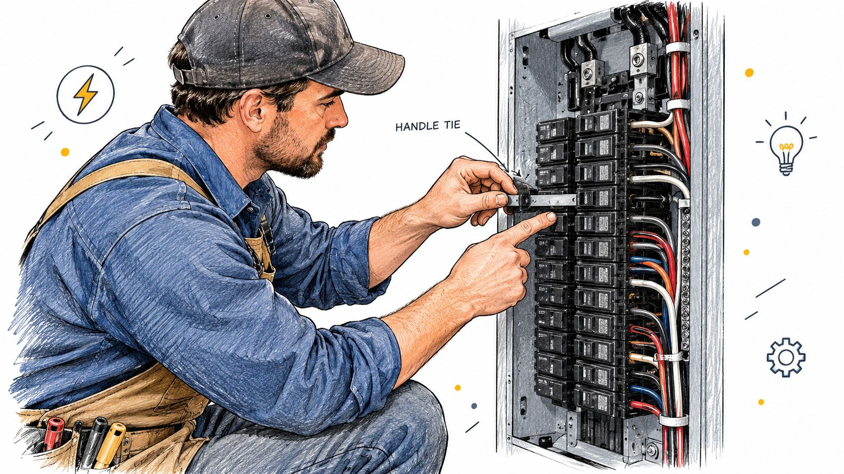
A breaker handle tie is a mechanical accessory used to connect the handles of adjacent single-pole breakers. In a shared-neutral multiwire branch circuit, it gives the electrician one linked operating point for the ungrounded conductors. The purpose is practical. A worker who switches the circuit off manually should not leave one ungrounded conductor energized while assuming the entire circuit is isolated.
The U.S. electrical code addresses this condition directly. NEC 210.4(B) requires a means of simultaneously disconnecting all ungrounded conductors at the origin of a multiwire branch circuit, while NEC 240.15(B)(1) permits individual single-pole breakers with identified handle ties for single-phase line-to-neutral loads. These provisions are summarized in manufacturer guidance on breaker handle ties and multiwire circuits.
What the tie actually does
The accessory transfers movement between the breaker handles. If an electrician manually moves one handle, the connected handle moves with it, creating the required simultaneous manual disconnect when the assembly is properly listed and installed.
That mechanical action is different from automatic operation during an overload or short circuit. A handle tie doesn't necessarily connect the internal trip mechanisms. If one single-pole breaker trips electrically, the other may remain closed. The ABB installation material referenced in the field guidance makes this distinction clear: a handle tie doesn't provide common tripping.
Field rule: A tied pair can satisfy a manual disconnect requirement in an approved application, but it isn't automatically equivalent to a two-pole common-trip breaker.
Why the distinction matters at the panel
The usual mistake is to inspect only the visible handles. A pair may look joined while using an accessory that isn't listed for the breaker, isn't secured correctly, obscures markings, or isn't suitable for the circuit voltage. A proper evaluation also considers the breaker model, panel compatibility, conductor arrangement, load type, and the behavior required when a fault occurs.
The small accessory therefore has two separate jobs in the conversation. It can provide linked manual operation, and it can support a compliant MWBC arrangement when the code and product listing allow it. It can't expand the breaker's electrical rating or supply a common-trip function that the breaker assembly wasn't designed to provide.
NEC Code Requirements for Simultaneous Disconnect
The starting point is the circuit, not the accessory. A multiwire branch circuit uses multiple ungrounded conductors with a shared grounded conductor. Because the conductors share a neutral, a person servicing one portion of the circuit needs a reliable way to disconnect the ungrounded conductors together at the circuit origin.
NEC 210.4(B) requires simultaneous disconnection of all ungrounded conductors of a multiwire branch circuit. That requirement can be met through an approved linked arrangement where the application permits it, or through a breaker assembly designed to operate the poles together. The field question is not whether two handles touch. It's whether the installed means is identified for the breakers and provides the required operation.
NEC 240.15(B)(1) permits individual single-pole breakers with identified handle ties for single-phase line-to-neutral loads. The word identified matters. A listed accessory matched to the breaker series is materially different from a wire, screw, nail, generic clip, or other improvised device.
Voltage rating remains a separate question
A handle tie is a mechanical component. It doesn't change the breaker's voltage rating, interrupting capability, or permitted application. Technical guidance on slash-rated breakers and shared-neutral applications emphasizes that appropriately marked breakers must be used within their voltage-to-ground limits.
A common field shortcut fails here. Two single-pole breakers may each be suitable for line-to-neutral loads, yet the pair may not be appropriate for a line-to-line load just because a handle tie has been added. A slash-rated breaker must be applied within the voltage-to-ground conditions for which it is marked. The tie doesn't turn an unsuitable pair into a compliant device for a different voltage relationship.
What to document on a submittal
For procurement and plan review, document the complete assembly rather than listing only “handle tie.” A useful specification identifies:
- Circuit arrangement: State whether the circuit is a shared-neutral MWBC and identify the ungrounded conductors.
- Load relationship: Confirm whether the loads are line-to-neutral or whether the conductors supply a line-to-line load.
- Breaker series: Name the manufacturer, breaker family, pole configuration, ampere rating, and voltage marking.
- Accessory identity: Specify the manufacturer's handle-tie accessory identified for that exact breaker series.
- Disconnect behavior: State whether the application needs simultaneous manual disconnect only or common tripping as well.
A plan reviewer or inspector can then verify the actual equipment against the documents. This approach also works well alongside broader arc-flash labeling requirements for electrical installations, because both tasks depend on accurate equipment identification and clear field documentation.
Handle Ties vs Common Trip Breakers
A handle tie and a two-pole common-trip breaker may occupy adjacent positions and present a similar front-panel appearance, but their internal behavior differs. The handle tie links operating handles. A common-trip breaker links the poles' trip functions inside the breaker assembly.
That difference becomes important during a fault. If one single-pole breaker in a tied pair trips, the mechanical tie may not force the other breaker to trip. The remaining breaker can stay closed, leaving part of the circuit energized. A two-pole common-trip breaker is designed so a qualifying trip event on one pole operates the linked trip mechanism for both poles.
| Feature | Handle Tie, Single-Pole Pair | 2-Pole Common Trip Breaker |
|---|---|---|
| Primary linkage | External mechanical connection between operating handles | Internal connection between both poles and their trip mechanisms |
| Manual operation | Both handles should move together when the listed accessory is correctly installed | Both poles operate together through the factory assembly |
| Automatic fault response | One pole can trip while the other remains closed because the tie doesn't provide common tripping | A trip on one pole operates both poles through the common-trip mechanism |
| Procurement check | Accessory must be identified for the exact breaker model and series | Breaker must be the correct factory-listed two-pole device |
| Typical code question | Is simultaneous manual disconnect sufficient and permitted for this application? | Does the circuit require common tripping or a factory common-trip assembly? |
| Improvised substitution | Unacceptable. A field-made tie doesn't establish listing or suitability | Not applicable. The common-trip function is built into the breaker |
When the handle tie can be appropriate
For a permitted single-phase line-to-neutral MWBC, an identified handle tie can provide simultaneous manual disconnect. The breaker pair still has to be correctly rated, installed in the permitted panel positions, and matched to the manufacturer's accessory. The installer must also account for the actual load and voltage arrangement, rather than assuming every adjacent pair is interchangeable.
The phrase manual disconnect should stay explicit in the specification. It tells the electrician and inspector what the accessory provides, and it prevents the common mistake of treating the pair as though it had an internal common-trip mechanism.
When common trip is the correct choice
A factory two-pole common-trip breaker is the appropriate choice when both ungrounded conductors form a single line-to-line circuit or when the application requires both poles to open under an automatic fault condition. It is also the safer specification when the project documents require common tripping and the manufacturer offers the correct factory assembly.
A handle tie shouldn't be used to approximate a two-pole breaker for a load that depends on both ungrounded conductors being disconnected and tripped together. For breaker sourcing and configuration review, ATEK's circuit breaker product range can be used as one procurement reference, but the final selection still has to match the panelboard, breaker series, rating, and application.
The question isn't “Can these handles be joined?” It's “What must happen when the circuit is manually switched off, and what must happen when one pole trips?”
Types of Handle Ties and Compatibility Rules
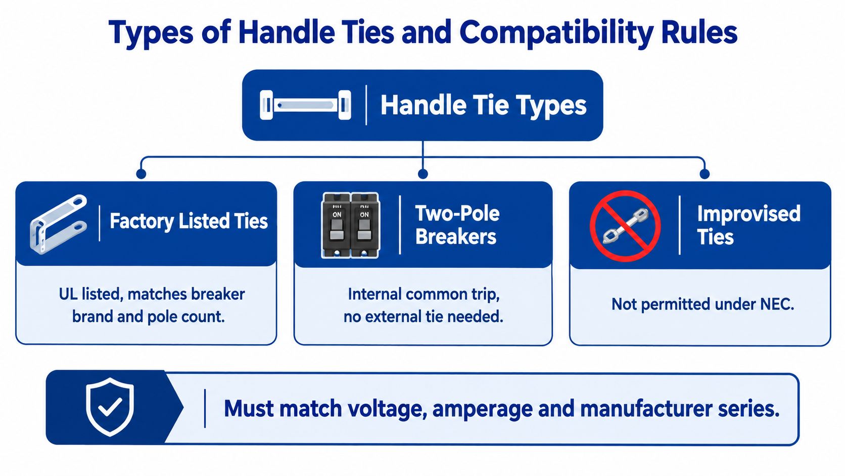
Handle ties aren't universal hardware. A tie that fits one breaker family may not fit another, may interfere with the handle geometry, or may lack the listing needed for that assembly. Procurement should begin with the breaker label and catalog information, not with a visual guess based on handle spacing.
Physical designs you may encounter
Rigid clip systems use a molded accessory that engages the two breaker handles. The clip must match the handle shape, spacing, and breaker family. A loose fit can allow independent movement or damage the handle mechanism.
Metal pin or bar systems use a dedicated connecting piece that passes through or engages designed features in the breaker handles. The installation method varies by manufacturer, so the product instructions control. Drilling, bending, or modifying the breaker face isn't an acceptable way to make a pin fit.
Factory-linked toggles are built into a multi-pole breaker or a manufacturer's integrated assembly. They don't depend on a separately sourced field accessory for the operating linkage, and a common-trip version also contains the required internal trip relationship.
The compatibility matrix
Use this sequence before ordering:
| Verification point | Acceptable evidence | Stop and investigate when |
|---|---|---|
| Manufacturer | Breaker and accessory come from the identified product family | Brand or product family is unknown |
| Series and model | Manufacturer literature names the exact series or compatible models | The listing says only “universal” or gives no model range |
| Pole arrangement | Accessory is designed for the installed adjacent poles | Breakers aren't positioned or configured as the accessory requires |
| Voltage application | Breaker markings match the circuit's line-to-neutral or line-to-line use | The tie is being used to overcome a voltage-rating mismatch |
| Listing and instructions | Product literature identifies the accessory for that breaker assembly | The accessory is generic, unmarked, or field modified |
| Panel acceptance | The breaker is permitted in the specific panelboard | The breaker itself isn't approved for the panel |
The exact breaker model and panelboard matter because a physically successful installation can still be electrically or administratively wrong. Older installations are especially prone to substitutions made after the original equipment became unavailable. If the original tie can't be identified, replacing the breaker pair with the correct listed assembly is often more defensible than trying to preserve an uncertain accessory.
What doesn't work
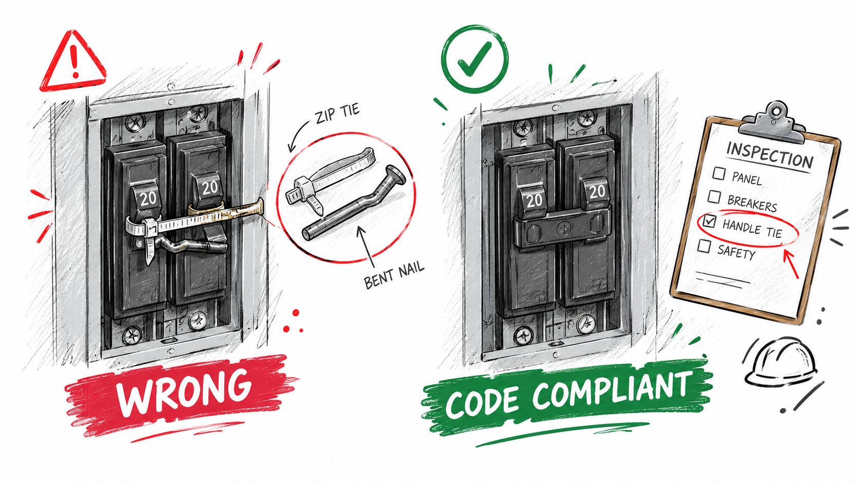
A zip tie, piece of wire, screw, nail, adhesive, or generic plastic clip doesn't establish a listed handle-tie assembly. It may prevent normal handle movement, create stress on the breaker housing, obscure the face markings, or fail during operation. It also gives an inspector no reliable basis for verifying the accessory's suitability.
For retrofit work, record a photograph of the breaker label, panel schedule, catalog designation, and installed tie before placing the order. That information gives the distributor or manufacturer a basis for confirming the accessory instead of guessing from a front-panel image.
UL Listing and Physical Installation Requirements
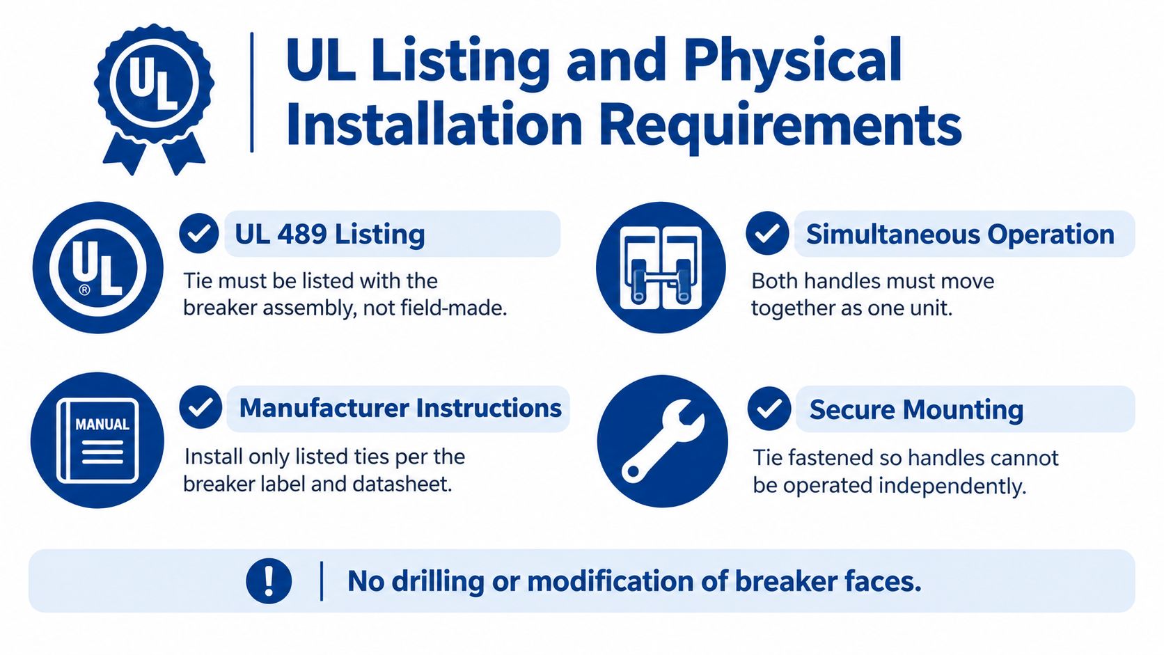
A listed handle tie has physical performance requirements that go beyond “the handles move together.” UL 489-based requirements specify that the tie must operate both breaker handles when either handle is manually operated, must not be readily removable, and must not obscure the ampere marking on either breaker, as summarized in the IAEI technical discussion of slash-rated breakers and shared neutrals.
Installation sequence
- De-energize and verify. Follow the site's lockout and verification procedure. Never rely on the panel handle position as proof that the conductors are dead.
- Identify the breaker pair. Confirm that the two breakers are the adjacent, compatible units named by the accessory instructions. Check the panelboard listing and circuit schedule.
- Set both handles to the same position. The manufacturer's instructions control, but installation generally begins with both breakers in the same physical position, commonly OFF. This avoids forcing one toggle against the other.
- Install the listed accessory. Engage the tie exactly as shown in the product instructions. Don't pry, drill, file, bend, or reshape the breaker housing.
- Test manual movement. Move either handle through its intended operating path and confirm that both handles move together. A tie that shifts, binds, or permits independent movement isn't ready for service.
- Inspect the markings. Confirm that the accessory doesn't hide the ampere marking or other required breaker identification.
- Record the assembly. Update the panel schedule and retain the product identification with the project documentation.
Why secure mounting matters
The accessory must not be readily removable during ordinary operation. That doesn't mean a worker can never remove it under controlled service conditions. It means the installed assembly shouldn't behave like a loose cap that can fall away, slide off, or be pulled off without the deliberate procedure intended by the product design.
A secure tie also protects the breaker from misuse. If the accessory doesn't match the handle geometry, the installer may apply pressure to the toggles or housing. That can create a mechanical problem even if the pair appears linked after installation.
The following video can supplement the written instructions, but it doesn't replace the breaker manufacturer's installation documentation or the authority having jurisdiction's requirements.
The final inspection should confirm operation, markings, secure retention, and product identity. Passing a simple movement check doesn't prove that the breaker pair is correct for the voltage or that the tie provides common tripping. Those are separate verification tasks.
Common Field Mistakes and Code Violations
The most serious errors usually start with a reasonable-looking shortcut. Someone sees two adjacent single-pole breakers, needs linked operation, and reaches for whatever is available. The result may hold the handles together physically while failing the listing, compatibility, and fault-response requirements of the installation.
Improvised ties
Nails, screws, wire, zip ties, and cut pieces of plastic aren't substitutes for an identified accessory. They don't establish that the breaker assembly was evaluated with that device, and they may prevent the breakers from moving as intended. A field-made connection can also obscure ampere markings or damage the handle mechanism.
Inspection test: If the installer can't identify the accessory by manufacturer documentation or the breaker assembly's listing information, treat the tie as unverified.
Wrong breaker family
A tie designed for one series may not engage another series correctly, even when the breakers look similar. Different handle dimensions, pole spacing, case geometry, and accessory retention methods can change the result. The same caution applies to older breakers installed in a replacement panel or modern breakers installed in an older panel without confirmation that the combination is permitted.
Confusing adjacent with compatible
Physical adjacency isn't enough. The pair must be the correct poles for the circuit, and the panel must accept the breaker arrangement. A tie installed across breakers that aren't intended to operate as a pair can create an ambiguous panel schedule and a service hazard.
Using a handle tie where common trip is needed
A tied single-pole pair isn't a replacement for a two-pole common-trip breaker when the circuit requires both ungrounded conductors to trip together. This mistake is particularly dangerous on line-to-line loads, where opening one conductor can leave the equipment partially energized.
The same principle applies to projects affected by jurisdiction-specific amendments. Before finalizing a retrofit or inspection response, review the applicable Minnesota NEC changes and confirm which edition and amendments govern the work.
Incomplete documentation
A panel schedule that says only “MWBC” doesn't tell the next technician whether the circuit uses a listed tie or a common-trip breaker. Record the breaker manufacturer, series, ampere rating, voltage marking, accessory identification, and the connected load arrangement. That record reduces repeat troubleshooting when a future service call involves a panel modernization or replacement.
Quick Reference Guide for Multiwire Branch Circuits
Use this field matrix before ordering parts or approving a panel alteration. It separates the manual disconnect question from the automatic trip question, which is where many incorrect substitutions begin.
| Circuit condition | Handle tie may be acceptable | Specify a 2-pole common-trip breaker |
|---|---|---|
| Single-phase line-to-neutral MWBC | When the code permits the arrangement, the breakers are compatible, and the handle tie is identified for the exact assembly | When the project specification or application requires common tripping |
| Line-to-line load | Don't treat a handle tie as a substitute based only on linked handles | Use the properly rated factory common-trip assembly |
| Fault isolation requirement | Not sufficient if one pole must force the other pole open automatically | Appropriate when both poles must trip together |
| Unknown existing equipment | Only after the breaker series, listing, panel acceptance, and circuit arrangement are verified | Preferred when the existing tie or breaker relationship can't be positively identified |
| Improvised or generic accessory | Never accept it as a compliant listed solution | Replace with the correct listed breaker assembly |
Rapid verification checklist
- Trace the conductors: Identify each ungrounded conductor and the shared grounded conductor at the panel.
- Confirm the load relationship: Determine whether the loads are line-to-neutral or whether the conductors supply a line-to-line load.
- Inspect the neutral: Verify that the grounded conductor is sized, routed, terminated, and identified according to the design and applicable code requirements.
- Read the breaker label: Record the manufacturer, series, model, pole count, ampere marking, and voltage marking.
- Verify panel acceptance: Confirm that the breaker is listed or identified for the panelboard.
- Match the accessory: Require manufacturer documentation naming the exact breaker family and handle-tie accessory.
- Check physical position: Confirm that the breakers are in the permitted adjacent positions and that the tie engages both handles.
- Operate the assembly: Move either handle manually and confirm that both handles move together.
- Check visibility: Ensure the tie doesn't obscure the ampere markings.
- Decide on trip behavior: Ask whether the application requires only simultaneous manual disconnect or automatic common tripping.
- Update records: Mark the panel schedule and retain the product documentation.
A clean result requires all of these checks to agree. A handle tie that passes the movement test can still be wrong for the voltage application, and a correctly rated breaker can still have the wrong accessory.
Glossary of Related Electrical Terms
Multiwire branch circuit, or MWBC: A branch-circuit arrangement with two or more ungrounded conductors and a grounded conductor that is shared by the circuit conductors. The shared neutral is why the ungrounded conductors need coordinated disconnect treatment at the circuit origin.
Ungrounded conductor: A current-carrying conductor commonly called a hot conductor. In an MWBC, each ungrounded conductor supplies its associated line-to-neutral load and participates in the circuit arrangement that must be evaluated for simultaneous disconnect.
Grounded conductor: The conductor intentionally connected to the grounded system point, commonly called the neutral. In a shared-neutral circuit, it serves more than one ungrounded conductor and must be considered in the circuit design, loading, routing, and maintenance procedure.
Simultaneous disconnect: An arrangement that opens all ungrounded conductors of the applicable circuit at the same time when the disconnecting means is manually operated. NEC 210.4(B) uses this concept for multiwire branch circuits.
Handle tie: A mechanical accessory that links the operating handles of compatible single-pole breakers. It provides coordinated manual handle movement, but it doesn't automatically mean the breakers have common-trip behavior.
Common trip: An internal breaker function that causes the linked poles to trip together when the breaker detects a qualifying fault condition on one pole. A factory two-pole common-trip breaker contains this relationship as part of its breaker assembly.
Two-pole breaker: A breaker assembly with two poles intended to operate as one device. The term alone doesn't communicate every detail of the trip mechanism, so the product documentation must still be checked for common-trip performance and application suitability.
Slash-rated breaker: A breaker marked with a voltage format that distinguishes voltage-to-ground limits from voltage-to-voltage limits. The marking must be applied as intended. A handle tie doesn't change those limits.
Line-to-neutral load: A load connected between an ungrounded conductor and the grounded conductor. This relationship is central to the situations where identified handle ties may be permitted under NEC 240.15(B)(1).
Line-to-line load: A load connected between two ungrounded conductors. It requires careful evaluation of breaker voltage ratings and disconnect behavior. A tied pair shouldn't be assumed to provide the same protection as a factory common-trip breaker.
Identified accessory: A manufacturer-recognized component specified for use with a particular breaker, series, or assembly. For a handle tie, identification means more than physical fit. It connects the accessory to the product listing and installation instructions.
Panelboard: The enclosure and distribution assembly that houses the breakers, bus structure, wiring terminations, and associated equipment. Breaker compatibility must be verified against the panelboard, not just against the breaker's appearance.
Trip-free operation: A breaker characteristic that allows the internal trip mechanism to open the circuit even when the operating handle is being held in the ON position. This is one reason an external handle tie shouldn't be assumed to transfer one breaker's automatic trip action to another.
Ampere marking: The breaker's current rating shown on the device. UL 489-based requirements call for a handle tie that doesn't obscure the ampere marking on either breaker, so the rating remains visible for inspection and service.
Factory common-trip device: A breaker manufactured with internal mechanisms that coordinate the poles during automatic tripping. It is the appropriate specification when the circuit requires both ungrounded conductors to open together during a fault.
Procurement verification: The process of matching the circuit requirements, breaker model, panelboard, voltage marking, accessory listing, and manufacturer instructions before purchase or installation. This is the step that prevents a generic “fits the handle” decision from becoming a field compliance problem.
ATEK Distribution helps contractors, engineers, and facility teams source circuit breakers, panelboard equipment, listed accessories, and related electrical hardware while supporting specification review and compliance documentation. Visit ATEK Distribution with the breaker model, panel information, and circuit requirements when you need a verified replacement or a compatible handle-tie solution.