
A panel schedule just landed with a service SPD, a distribution SPD, and a point-of-use unit. The three part numbers differ mainly by a Type mark and a large surge-current figure. That package can still be the wrong buy. Surge protection devices types name a permitted place and a test duty. They don't rank quality, and a bigger kiloampere claim doesn't finish the selection.
The service device may be marked only for the load side of the service overcurrent device. The downstream unit may clamp at a voltage the controls can't ride through. A communications line or a DC circuit may have been given an ordinary AC panelboard device. Work the checks in order. Match the mark to the location, the waveform to direct-lightning versus induced or switching duty, then continuous voltage, let-through, discharge current, and short-circuit rating. Stage the devices so the upstream unit takes the higher-energy event and the downstream unit cuts residual voltage near the load.
Table of Contents
- Where a Surge Spec Usually Goes Wrong
- Where Surge Protection Devices Types Belong
- Why Type Labels Are Not a Quality Ranking
- How SPD Elements Handle the Surge
- Specs That Separate One SPD from Another
- Protection Layouts for Real Facilities
- Selecting SPDs During BOM Review
Where a Surge Spec Usually Goes Wrong
The submittal looks complete on a first pass. Three devices, three locations, three surge-current headlines. The service entrance calls for protection ahead of, or at, the main overcurrent device. The distribution panel calls for a second device. Sensitive controls call for something at the equipment. Procurement lines them up by ampere claim and treats the Type mark as a grade.
That comparison misses the failure modes that show up after the gear is on site. A device investigated only for load-side use can't fill a line-side service location just because the enclosure matches the switchboard. A branch device with a high surge-current number can still let through more voltage than a PLC, drive, or medical load will tolerate. An AC panelboard SPD on a PoE run, a PV DC circuit, or another DC power circuit is the wrong family of device, not a close alternate.
What the cut sheet didn't settle
The package fails for reasons that never appear in the surge-ampere column.
- Location mismatch: The service unit's marking doesn't permit the side of the service overcurrent device where the one-line puts it.
- Let-through mismatch: The downstream clamp voltage sits above the withstand of the control equipment, so the load still sees a damaging residual.
- Circuit-family mismatch: Communications, photovoltaic DC, or another DC circuit received an AC power SPD.
Practical rule: The type name starts the selection. It doesn't finish it.
Those misses also show up as nuisance trips, burned equipment, and warranty arguments that trace back to power quality issues the SPD was supposed to limit. The rest of a defensible spec is a sequence, not a bigger catalog number. Confirm where the mark may be installed. Confirm whether the test waveform matches direct lightning current or induced and switching duty. Then compare continuous voltage, protection level, nominal discharge current, and short-circuit rating against the system in front of you.
Where Surge Protection Devices Types Belong
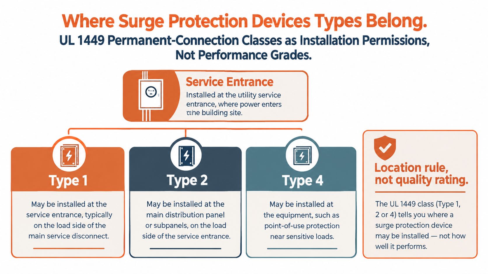
UL 1449 sorts permanently connected surge protective devices by where they may be installed. The classes are installation permissions, not performance grades. Place the mark on the one-line before anyone argues about joules or kiloamperes.
Under that classification, a Type 1 SPD may be installed between the service transformer secondary and either the line or the load side of the service-equipment overcurrent device. It is intended to operate without an external overcurrent protective device. A Type 2 SPD is installed on the load side of that service overcurrent device, including branch panels. A Type 3 device is a point-of-use product, cord-connected, plug-in, or receptacle, and the conductor length from the service panel to the utilization point must be at least 10 meters (30 feet), per UL's SPD classification summary.
A sketch before the ratings
Think of the building in three stops, and assign the mark before you open a datasheet.
- Service entrance. This is the only stop where a line-side landing is even in play. The device has to carry a Type 1 evaluation if the design puts it on the line side of the service overcurrent device, or if the spec calls for a device intended to run without an external overcurrent protective device.
- Distribution and branch panels. These land on the load side of the service overcurrent device. A Type 2 mark fits that location, including panels that feed industrial equipment.
- Utilization equipment. A Type 3 plug-in, cord, or receptacle device belongs here, and only when at least 10 m (30 ft) of conductor separates that point from the service panel.
What procurement has to reject
A branch-panel device doesn't become a service device because the enclosure looks similar or the surge-current claim is larger. A line-side or other Type 1 location needs the Type 1 evaluation on the marking. A point-of-use strip doesn't replace the service or distribution device, even when the conductor-length rule is met.
The mark tells you the legal landing. It doesn't tell you the device is adequate for the exposure.
Contractors can use that sketch on a walkthrough. Service gear gets the Type 1 question first. Distribution panels get a Type 2 question. The receptacle or cord device is a supplement at the load, and only past the 10 m conductor boundary. Sensitive industrial equipment still needs the service and distribution layers. The point-of-use unit is not the scheme.
Why Type Labels Are Not a Quality Ranking
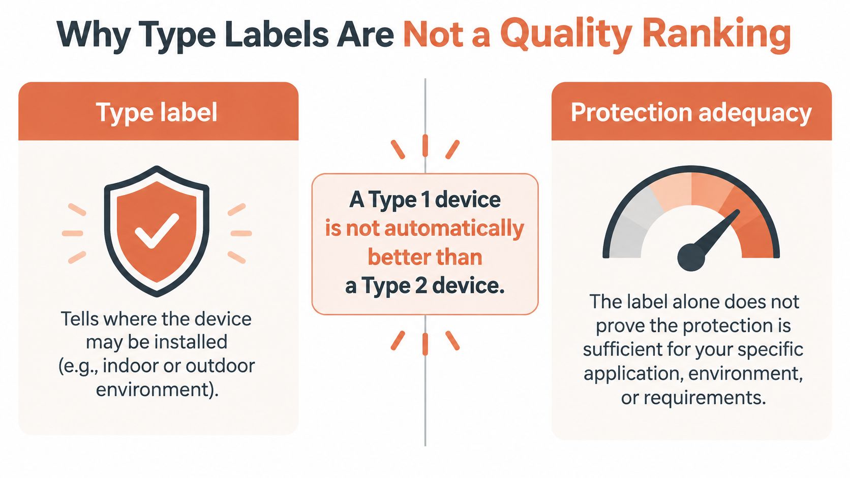
A higher type number is not better protection. Treat the common upgrade path, Type 3 to Type 2 to Type 1, as a location map someone misread as a performance ladder.
A Type 1 device isn't automatically better than a Type 2 device. A Type 3 plug-in unit isn't a stand-in for coordinated protection at the service and at distribution. UL 1449's type structure describes where the device may be installed. Adequacy is a separate question, and the label alone doesn't answer it.
Location marks versus test class
The IEC duty split is about the transient, not a grade.
- Type 1 duty, IEC framing: These devices are for locations where a portion of lightning current may enter the installation. You can't assume a Type 2 device replaces that duty where higher-energy lightning current is expected.
- Type 2 duty: These devices protect downstream distribution against induced lightning effects and switching transients.
- Type 3 duty: These devices give localized, equipment-level protection. They don't absorb the service event by themselves.
IEC Class I uses a 10/350 μs waveform associated with direct-lightning exposure. Class II uses an 8/20 μs waveform for switching surges or indirect lightning. Those shapes aren't interchangeable labels. A device proven on the shorter switching waveform hasn't been shown, by that test alone, to carry partial lightning current at the service.
What to ask for on the submittal
Ask for two things, and don't let either one stand in for the other.
| Ask | What it settles | What it doesn't settle |
|---|---|---|
| Marked UL type | Permitted installation location | Whether let-through and fault rating fit the load |
| IEC test class and waveform | Direct-lightning (10/350 μs) versus induced or switching (8/20 μs) duty | Which side of the service overcurrent device is legal |
A facility with an external lightning protection system, or a service where part of the lightning current can enter, needs the higher-energy duty called out. A plant whose main threat is contactor and drive switching still needs distribution devices tested for that induced and switching waveform. Buying "Type 1 everywhere" wastes locations where a Type 2 device is the correct landing and still leaves residual voltage at the load if nothing is staged downstream.
How SPD Elements Handle the Surge
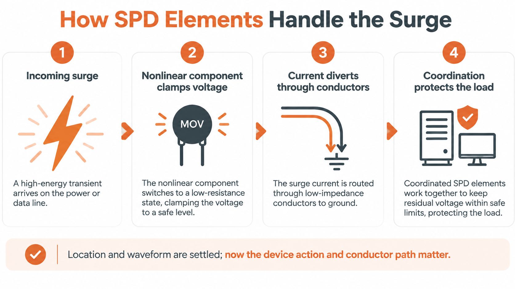
An SPD contains at least one nonlinear component whose job is to limit surge voltage and divert surge current. IEC 61643 is the reference for that definition and, in IEC 61643-12, for selection, location, operation, and coordination on 50/60 Hz AC systems up to 1,000 V RMS. Naming that role isn't a substitute for the applicable code, the listing, or the manufacturer's instructions.
Three element behaviors
Voltage-limiting parts, metal-oxide varistors or avalanche components, reduce impedance continuously as voltage rises. They clamp fast transients. They also leak, run warm, and age. A limiting element that looks "always ready" is also a thermal and end-of-life problem the panel has to live with.
Voltage-switching parts, such as gas-discharge devices, stay comparatively high impedance until a breakdown threshold, then conduct heavily. Surge-current capability can be high. Let-through can also be higher, and follow current has to be considered, because the device may keep conducting after the surge until the system voltage and the circuit allow it to extinguish.
Hybrid assemblies combine the two. The switching element takes energy. The limiting element holds residual voltage down. That balance is the point. A high surge-current element can still hand the load too much voltage if nothing clamps the front of the wave.
Leads are part of the scheme
Coordination is the layer outside the case. Upstream and downstream devices have to be chosen together, and the connecting conductors have to be short and straight. Lead length adds voltage while surge current is flowing. A tidy loop of extra wire can erase the clamp the cut sheet advertised.
The check that matters at the load is simple. The downstream device's voltage protection level has to remain below the equipment withstand level. If the upstream hybrid handles energy but the downstream leads are long, the control power supply still sees a high residual. Installers should treat conductor geometry as protection design, not as a neatness item on the punch list. IEC 61643-12 is the coordination reference for those AC systems. It doesn't replace the project engineer's withstand review.
Specs That Separate One SPD from Another
Behavior inside the case doesn't replace the side-by-side rating check. Nominal system voltage and a surge-current headline aren't enough to accept a substitute. UL certification records identify maximum continuous operating voltage (MCOV), voltage protection rating (VPR), nominal discharge current (In), short-circuit current rating (SCCR), phase configuration, and protection mode.
One documented UL-listed Type 2 device for a 120 V single-phase system shows how those numbers read in job language. The record lists a 150 V MCOV, 400 V VPR line-to-neutral and line-to-ground, 500 V VPR neutral-to-ground, 3 kA nominal discharge current, and 5 kA SCCR, according to the UL certification record for that Type 2 SPD. Those figures are an example of what a listing contains. They aren't a target to copy onto a 480 V board.
Ratings to compare on an SPD cut sheet
| Parameter | Example from the listing | What to verify |
|---|---|---|
| MCOV | 150 V | Sits above the continuous voltage the grounding arrangement actually applies |
| VPR, L-N and L-G | 400 V | Let-through versus equipment withstand, mode by mode |
| VPR, N-G | 500 V | Neutral-to-ground mode isn't the same number as the line modes |
| In | 3 kA | Discharge current used in the nominal test, not the largest marketing surge claim |
| SCCR | 5 kA | Compatible with available fault current, plus any required backup overcurrent protection |
| Marked type and phases | Type 2, 120 V single-phase | Location permission and system configuration match the one-line |
MCOV is a withstand-the-system number. Set it from the actual continuous voltage, including how the system is grounded, not from the nominal nameplate alone. VPR is the let-through figure. Compare it mode by mode. A device that looks fine line-to-neutral can still be the wrong clamp neutral-to-ground.
In is the nominal discharge current in the listing. It isn't the catalog surge-ampere banner. SCCR has to live with the available fault current at that panel. If the listing requires backup overcurrent protection, that device has to be on the bill too. A deeper pass on how surge protection ratings are read keeps two candidates from being compared on mixed modes.
If MCOV, VPR, In, SCCR, or the marked type doesn't fit the system, a larger surge-ampere number doesn't save the substitution.
Protection Layouts for Real Facilities
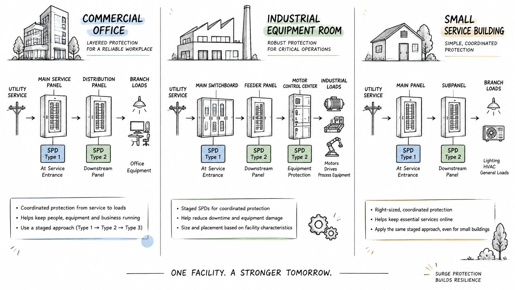
Individual ratings become a scheme only when each device has an exposure, a panel, and a load. The diagram below is the pattern. Service duty first, distribution next, equipment last. One part number doesn't cover the building.
Three AC layouts
Commercial or institutional service. Where the design expects service-entrance duty, specify a Type 1 device, or a device marked for both Type 1 and Type 2, at the service. Put Type 2 devices at distribution or branch panels so induced and switching energy doesn't travel the full feeder into lighting and HVAC controls. The service unit takes the higher-energy event. The panel units cut what remains.
Industrial control lineup. Keep the panel SPD on the load side of the service overcurrent device. Add localized protection only where conductor distance and a sensitive load justify a Type 3 device, such as a PLC rack or a drive that has already shown surge damage. A 100 A class distribution point is a common place this decision shows up. The panel device and the feeder arrangement on a 100-amp 3-phase panel still have to match the marked type before anyone adds a receptacle SPD.
Data room or healthcare branch. Treat the plug-in or receptacle device as the last reduction of residual voltage at servers, nurse-call gear, or imaging controls. It isn't the only SPD on the building. Upstream service and distribution devices still have to be there. The point-of-use unit cleans up what those stages let through.
The short video below walks the same staging idea from service to equipment. Use it as a briefing clip, then put the marks on your own one-line.
Circuits that are not AC panel SPDs
A power-panel type mark doesn't transfer to every circuit on a modernization. IEC 61643 standards for other circuits draw that line clearly.
- Telecommunications and signaling: IEC 61643-21:2025 covers SPDs on those networks up to 1,000 V RMS and 1,500 V DC, including lines that also carry power, such as Power over Ethernet. Clamping or switching elements here aren't an AC panelboard SPD with a different label.
- Photovoltaic DC: IEC 61643-31:2018 covers SPDs on the DC side of PV systems up to 1,500 V DC, including PV generator and inverter DC. It addresses permanently connected devices that need a tool for removal, and it excludes portable SPDs.
- Other DC power: IEC 61643-41:2025 covers SPDs for DC low-voltage power circuits up to 1,500 V DC.
Stop the substitution when the circuit family changes. PoE, PV generator DC, and a DC power circuit each need their own device standard. An AC Type mark on the panel schedule doesn't cover them.
Selecting SPDs During BOM Review
Drawing the one-line and buying the alternate are different jobs. On alternate-product review, compare the complete certification marking. A similar voltage, a similar enclosure, or a similar surge-current claim isn't a match.
Under UL 1449, an SPD investigated for Type 1 applications is suitable for Type 2 applications and may be marked for both. An SPD marked only Type 2 isn't suitable for a Type 1 installation. That checkpoint is documented in the UL record on Type 1 and Type 2 marking. A line-side or other Type 1 location can't be filled with a Type 2-only device.
The pass that rejects a bad alternate
Run the markings in one pass, and stop at the first miss.
- Application category: Type 1 where the spec requires Type 1. A dual mark is acceptable for a Type 2 landing. A Type 2-only mark isn't acceptable for a Type 1 landing.
- Electrical fit: Nominal system voltage, MCOV, VPR by mode, nominal discharge current, SCCR, and phase configuration have to agree with the system.
- Protection hardware: Any required backup overcurrent device is on the bill, not assumed.
- Documentation: The manufacturer's certification marking and application category are in the submittal, not reconstructed from a catalog photo.
ATEK Distribution can review that bill of materials, chase a hard-to-source protective device, coordinate with the manufacturer, and check an approved alternate when lead time threatens a service, distribution, or controls package. Send the one-line location, system voltage, available fault current, and the marked type the spec requires. Ask for availability and documentation, and accept a like-for-like alternate only when the markings match the location. Applicable codes, the manufacturer instructions, and the project engineer still govern the installation.
ATEK Distribution helps engineers, contractors, and procurement teams source surge protective devices and the distribution gear around them, including hard-to-find alternates and the certification markings a submittal needs. If a service, panel, or controls package is waiting on the right SPD, send the location and the required type. Visit ATEK Distribution to start a BOM review or a quote.