
If you're staring at a BOM, a damaged field unit, or a substitution request that says “same plug, different vendor,” pin sleeve connectors are where the easy assumptions start to break down. The connector may fit, but that doesn't mean it belongs on the job, especially when voltage, phase, current, ingress protection, conductor type, and listing all have to line up before anyone signs off.
Table of Contents
- What Are Pin Sleeve Connectors
- Origins and the IEC 60309 Standard
- Ratings, Poles, and Color Clock Keying
- UL 1682 vs IEC 60309 for North American Projects
- Conductor Compatibility and Assembly Markings
- Installation Practices and Field Safety
- Diagnosing Overheating Before Failure
- Compatibility Matrix and Substitution Review
- Quick Reference for Specifying and Sourcing
What Are Pin Sleeve Connectors
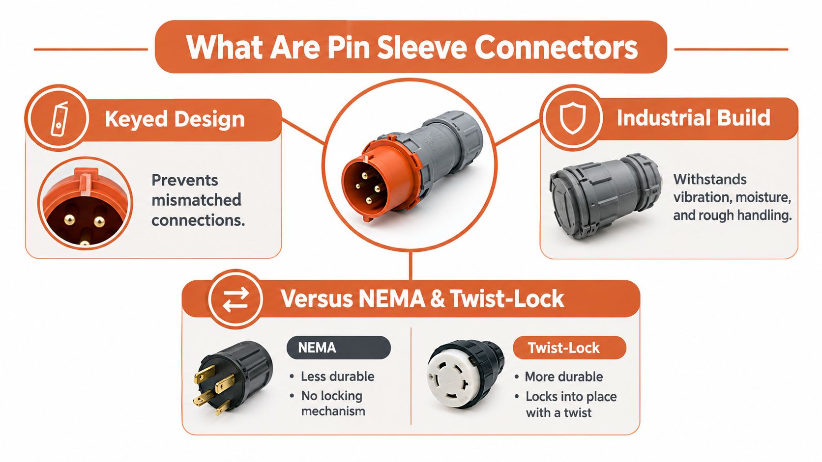
Pin sleeve connectors are rugged, keyed industrial plugs and receptacles built so the wrong connection is hard to make and easy to avoid. In practice, that means a pin, sleeve, and protective-earth arrangement designed for harsh service, not the loose-fit convenience of a light-duty cord cap.
Why the format exists
The value is mechanical and electrical keying. Each configuration is built to mate with only one matching socket arrangement, which helps prevent incompatible voltage, frequency, or phase connections. That's a big reason these devices show up on construction sites, in manufacturing, around utilities, in temporary power setups, and in entertainment power where people need deliberate incompatibility, not improvisation.
Where they sit compared with ordinary plugs
Standard NEMA devices and twist-locks solve some applications well, but they don't give you the same industrial keying structure or the same intentional separation between electrical systems. Pin sleeve connectors are chosen when the cost of a wrong connection is higher than the extra attention the device demands. They also bring the protective-earth connection into the design, which matters whenever the equipment is going to be handled, moved, or connected in the field.
Practical rule: if the job site has more than one voltage system, the connector family should do part of the safety work for you.
That's why specifiers treat this format as an industrial interface, not just a plug. The rest of the selection process is about proving that the connector family, rating, and listing all match the project, not just the opening in the wall.
Origins and the IEC 60309 Standard
The modern pin sleeve connector family traces back to the CEE 17 industrial plug-and-socket standard developed in the 1960s. It was published in Europe in 1966, entered the IEC framework as IEC 309 in 1969, and was later renamed IEC 60309. The United Kingdom aligned with the design as BS 4343 in 1968, which shows how quickly the format moved from a European industrial initiative into broader use. Historical overview of CEE 17 and IEC 60309
Why that history matters on real projects
That background isn't trivia. It explains why one connector family can be recognized as IEC 60309, pin-and-sleeve, or CeeForm depending on the market and application. The same industrial geometry carried through different regions because it gave buyers a stable way to specify dimensional, wiring, and safety requirements across multiple markets.
For procurement teams, that consistency is the whole point. If a project spans borders or uses mixed sourcing channels, a connector conforming to IEC 60309 can be evaluated against the same basic mechanical and safety expectations instead of being treated as a one-off custom item. That lowers substitution risk, but only if the full rating still matches the job.
What IEC 60309 covers
IEC 60309 covers plugs, socket-outlets, connectors, couplers, and appliance inlets for industrial applications. Its core design principle is compatibility control, not universal interchangeability. Mechanical and electrical keying helps keep incompatible systems apart, and that remains the reason the format is still recognized decades after its introduction.
A connector family stays relevant when buyers can repeat the same specification logic from one market to the next.
Ratings, Poles, and Color Clock Keying
Pin sleeve connectors are not one connector size with one current class. They span a broad electrical range, and the first mistake buyers make is treating the housing shape as the selection criterion. The key filter is a combination of voltage, current, poles, grounding, frequency, and enclosure protection.
Selection variables that actually matter
IEC technical summaries identify standard limits up to 1,000 volts AC or DC, 800 amperes, and 500 hertz. Common IEC current classes include 16 A, 32 A, 63 A, 125 A, and 200 A, while North American product families often include 30 A, 60 A, 100 A, 200 A, and 400 A versions. The system supports 2P+E, 3P+E, and 3P+N+E arrangements, so the same broad family can serve single-phase, three-phase, or three-phase-plus-neutral loads. Industrial and multiphase power plug summaries
Environmental protection is separate from electrical rating. Commercial devices are offered with ratings such as IP66, IP67, IP68, and IP69K, but that doesn't mean every product in the family carries every protection level. For outdoor, washdown, or temporary service, the actual assembly has to be checked, not assumed.
Color and clock position
IEC 60309 also uses housing color and clock-position keying to reduce mis-mating. Yellow commonly identifies 100 to 130 VAC, blue identifies 200 to 250 VAC, gray identifies 277 VAC, red identifies 380 to 480 VAC, and black identifies 500 to 690 VAC. The grounding contact sits at one of 12 clock positions in 30-degree increments, so voltage and frequency identity are confirmed both visually and mechanically. IEC 60309 color and clock keying reference
| Voltage Range | Housing Color | Clock Position | Typical Use |
|---|---|---|---|
| 100 to 130 VAC | Yellow | Varies by configuration | Lower-voltage industrial or temporary circuits |
| 200 to 250 VAC | Blue | Varies by configuration | Common industrial single-phase and three-phase applications |
| 277 VAC | Gray | Varies by configuration | Building and facility power systems |
| 380 to 480 VAC | Red | Varies by configuration | General industrial distribution and machinery |
| 500 to 690 VAC | Black | Varies by configuration | Higher-voltage industrial applications |
What the color code doesn't do
Color helps, but it doesn't complete the spec. Current rating, phase arrangement, grounding/neutral configuration, ingress protection, and regional certification still have to be verified. A connector can look right and still be wrong for the load, which is why substitution review has to go deeper than physical fit.
UL 1682 vs IEC 60309 for North American Projects
North American buyers usually live in two worlds at once. On one side is the global IEC family, and on the other is the UL and CSA framework that governs many domestic projects. If you're building for a U.S. or Canadian site, the list on the submittal has to match the code path the AHJ and design team expect.
The North American listing path
For North American projects, specify pin-and-sleeve plugs, receptacles, power inlets, and cable connectors against UL 1682 and, where applicable, the harmonized CSA C22.2 No. 182.1 requirements. UL 1682 covers devices rated up to 800 A and 600 V AC or DC, including configurations with up to eight pilot contacts, for branch-circuit use with copper conductors in indoor or outdoor nonhazardous locations. UL 1682 scope summary
How it differs from IEC 60309
IEC 60309-1 and IEC 60309-2 are the principal framework for globally deployed industrial interfaces. They rely on dimensional and color keying, and the IEC framework extends to devices up to 690 V with current classes typically discussed up to 125 A or higher depending on product category and source summary. The point isn't that one standard is “better.” It's that the project market and approval path decide which listing belongs in the BOM.
| Attribute | UL 1682 / CSA C22.2 | IEC 60309-1 / 60309-2 |
|---|---|---|
| Region | North America-focused | Global industrial use |
| Devices Covered | Plugs, receptacles, power inlets, cable connectors | Plugs, socket-outlets, connectors, couplers, appliance inlets |
| Electrical Scope | Up to 800 A, 600 V AC or DC | Up to 690 V in the IEC framework, with defined current classes |
| Keying Method | Listing and product configuration details | Dimensional keying, color coding, clock position |
| Typical Use | North American branch-circuit projects | Multinational industrial and temporary power systems |
What belongs in the submittal
Include the actual listing, the marked voltage and current, the pole and pilot-contact configuration, and the installation scope. Certification doesn't override the device's marked ratings, and it doesn't replace NEC or manufacturer instructions. If the project is U.S.-based, that paperwork matters as much as the connector body itself.
Conductor Compatibility and Assembly Markings
A connector spec that ignores the conductor is only half a spec. The device rating has to align with the cable, the termination method, and the way the assembly is built.
Read the markings as a full assembly check
UL 1682 expects copper conductors, and that single detail already rules out a lot of lazy substitutions. The listed wire range, conductor size, cable diameter range, strain relief, and temperature rating all have to fit the exact assembly. An ampere marking tells you the family, but it doesn't prove the terminal, jacket, or entry system will accept the actual cable on site.
That's why a connector from the right family can still fail a submittal. Fine-stranded and class B conductors can behave differently at termination, and the assembly may need a specific ferrule or termination approach to stay within the listing. If the connector body is certified but the cable entry isn't, the whole assembly is still wrong.
For cable terminations that need clean conductor preparation before the plug or inlet is built, a practical reference like this ferrule crimp guide can help crews avoid sloppy end prep. On the cable side, a product set such as 22kW cables at EVChargers.eu is a useful reminder that the conductor side of a power connection is part of the specification, not an afterthought.
What to verify before approval
- Conductor material: Confirm the listing matches the actual conductor material, especially on branch-circuit work.
- Wire size range: Check the terminal's accepted range, not just the amp rating stamped on the housing.
- Cable entry: Match the jacket diameter to the strain-relief window.
- Temperature rating: Make sure the conductor insulation and connector terminal ratings work together.
- Termination method: Verify ferrules, lugs, or direct terminations only where they're explicitly accepted.
A connector can be the right current class and still be a bad fit if the wire range or strain relief doesn't match the cable on the truck.
Installation Practices and Field Safety
The best-listed connector still fails if it's installed carelessly. Torque, strain relief, and the way the assembly is handled on the jobsite decide whether the device performs as intended.
What disciplined installation looks like
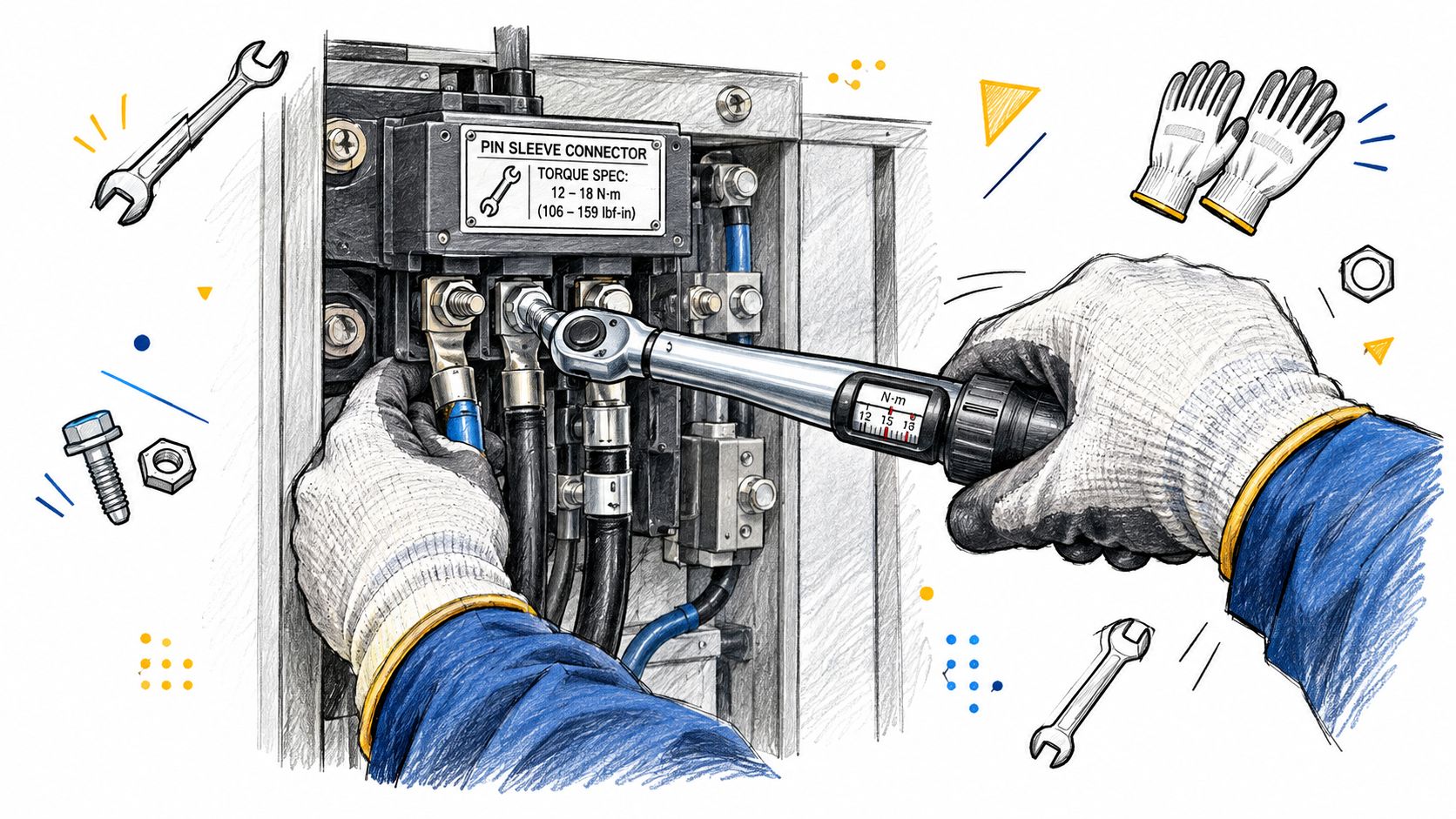
Start with the manufacturer's listed torque values, not a feel-based tighten-and-hope method. Then match the cable jacket and conductor diameter to the listed strain-relief range, because a connector body that grips the wrong cable size can loosen, overheat, or fail mechanically under vibration. Wiring strain relief reference
The assembly also has to be seated and locked correctly. If the device is tested for load make-and-break, that doesn't mean an installer should treat live disconnection as routine practice. De-energize before unplugging unless the manufacturer and the application specifically allow otherwise under the applicable rules.
Code and enclosure checks
UL certification authorizes use only within the device's marked ratings. It doesn't override the NEC, manufacturer wiring instructions, or local code requirements. For washdown and outdoor service, confirm the IP rating on the complete mated assembly, not just on the catalog line for the connector family.
The field failures that show up again and again are simple: loose terminals, wrong cable size, damaged locking features, and assemblies left half-seated. Those are avoidable when the install crew treats the connector as a controlled electrical interface, not just a rugged plug.
Diagnosing Overheating Before Failure
A connector can still pass power and still be unsafe. That's the part most maintenance programs miss, because “it still works” is not the same thing as “it's thermally healthy.”
Why heat is a warning, not a byproduct
Contact resistance in connectors is measured in milliohms, so normal heating is usually small. When a connector runs hot, the problem is usually excessive current or a contact defect that creates a localized hot spot. A loose connection is especially risky because it can arc and heat without enough overcurrent to trip upstream protective devices. Electrical-connection failure guidance
A practical inspection workflow
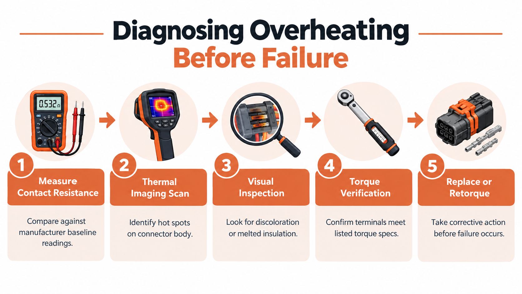
- Inspect visually. Look for discoloration, contamination, looseness, damaged sleeves, or insulation deterioration.
- Compare temperatures. Check the connector body against the attached conductor under representative load.
- Use infrared thermography. A thermal scan helps find hot spots that aren't obvious during a quick walkdown.
- Verify the termination. Recheck torque and locking condition if the temperature pattern looks abnormal.
- Repair or replace. If the connector is running hotter than the conductor, treat that as a functional failure.
Functional rule: a connector hotter than its conductor has already failed the maintenance test, even if the circuit is still live.
The threshold that matters
Thermal inspection is separate from upstream protection. A breaker that hasn't tripped doesn't prove the connection is healthy. Maintenance teams often use 90°C or the insulation limit as the lower threshold for corrective action, but the true trigger is the temperature behavior of the assembly under load. The point is to catch degradation before it becomes a burn-up, not after.
Compatibility Matrix and Substitution Review
Mechanical fit is the starting point, not the approval decision. Two connectors can mate cleanly and still fail the project because one of the hidden variables doesn't match.
What belongs on the review sheet
Substitution review should capture voltage and frequency, phase and pole count, ampacity, grounding and neutral configuration, ingress protection, hazardous-location suitability, cable type and termination method, temperature, duty cycle, and local code approval. That list is long because the project risks are real. A plug that fits the receptacle can still be rejected if it fails the environmental spec or the wiring method.
A practical procurement checklist
| Variable | Verification Required | Approval Evidence |
|---|---|---|
| Voltage and frequency | Must match the system and application | Device marking, submittal, catalog data |
| Phase and pole count | Must match the power arrangement | Wiring diagram, product literature |
| Ampacity | Must suit the load and protective device | Rating label, listing documentation |
| Grounding and neutral | Must match the circuit design | Configuration code, cut sheet |
| IP or enclosure rating | Must fit the environment | Listed enclosure rating for the complete assembly |
| Cable type and termination | Must match the actual conductor and entry | Wire range, terminal data, installation instructions |
| Code approval | Must satisfy the project jurisdiction | Approved submittal, AHJ review if required |
What buyers should reject
If the vendor only proves that the plug fits, that's not enough. If the alternate has the right amperage but the wrong grounding clock, the wrong cable entry, or the wrong environmental rating, it's still the wrong part. That's the kind of failure that shows up late, after the shipment is already on the dock.
A clean review package beats a rushed field correction every time.
Quick Reference for Specifying and Sourcing
The fastest way to specify pin sleeve connectors is to stop thinking of them as one item and start treating them as a controlled assembly. Pick the standard first, then the electrical rating, then the environment, then the conductor and termination details.
Quick decision path
- Choose the standard: Use UL 1682 / CSA C22.2 No. 182.1 for North American projects, or IEC 60309 where the global industrial format is acceptable.
- Match the keying: Confirm color and clock position before approving a replacement.
- Verify the load path: Check voltage, current, poles, grounding, and frequency together.
- Check the cable side: Confirm conductor material, wire range, strain relief, and temperature rating.
- Confirm the enclosure: Don't infer IP performance from the connector family name.
- Review the paperwork: Installation instructions, product markings, and listing documentation belong in the submittal set.
Good sourcing habits
When a project is short on time or the exact part is hard to find, the substitute still has to pass the full compatibility check. A generic “same family” match won't help if the cable entry, rating, or certification is off. For cable and cord sourcing support that fits into a broader industrial BOM review, wire cords and cables is a useful category to keep in mind during procurement planning.
The best alternate part is the one that survives both the spec review and the field install.
If you're comparing replacements, building a submittal, or trying to keep a mission-critical job moving, ATEK Distribution can help with BOM review, hard-to-source pin sleeve components, approved alternatives, and compliance documentation. Visit ATEK Distribution to request sourcing support and keep the project moving with the right electrical components.