
You've opened a dark fixture expecting a lamp change, but the replacement tube won't start. The ballast label is faded, the spare on the truck looks close, and maintenance needs the area back in service. Choosing a ballast for T5 lamps at that point requires more than matching the wattage printed on the glass.
The useful question isn't whether the replacement fits inside the housing. It's whether the replacement matches the complete electrical system, and whether repairing that fluorescent system still makes sense.
Table of Contents
- Why T5 Ballast Selection Goes Deeper Than Lamp Wattage
- Electronic Versus Magnetic T5 Ballasts
- Identifying the Correct Ballast for a T5 Fixture
- Wiring and Installation Practices for T5 Ballasts
- Repair, Replace, or Retrofit to LED
- Troubleshooting Common T5 Ballast Failures
- Sourcing, Compliance, and Next Steps for T5 Projects
Why T5 Ballast Selection Goes Deeper Than Lamp Wattage
Consider a replacement that bolts into the existing mounting holes and lists the expected lamp wattage. After installation, the lamps start poorly or the fixture no longer responds correctly to its controls. That's a hypothetical service call, but it illustrates the selection error: mechanical fit and nominal wattage don't establish compatibility.
The missing detail might be the supply-voltage rating, starting method, supported lamp count, or control interface. A different ballast factor can also change the fixture's output even when the lamps appear to operate normally.
Treat the fixture as an assembly
The ballast, lamps, sockets, controls, and fixture wiring have to work together. Substituting a component without identifying the rest of that assembly turns a straightforward repair into troubleshooting by trial and error.
Before requesting a replacement, separate what you know from what you're assuming:
- Confirmed information: Legible lamp markings, ballast model, fixture label, supply identification, and control model.
- Unverified information: A replacement someone previously installed, a handwritten stockroom description, or an assumption based on the neighboring fixture.
- Missing information: An unreadable wiring diagram, undocumented emergency equipment, or sockets whose configuration hasn't been inspected.
Practical rule: An installed component is evidence of what's present, not proof of what belongs there.
This distinction matters especially in buildings maintained through several repair cycles. Don't automatically reproduce the last technician's substitution. Compare the installed equipment with the fixture documentation and the proposed manufacturer's application data.
Define an acceptable replacement before ordering
For a maintenance repair, the objective is usually to restore the intended operation without changing the lighting design or controls. For a planned upgrade, a different output or control arrangement may be acceptable, but it needs engineering approval rather than an undocumented field substitution.
A useful purchasing description therefore identifies the operating requirements, not just a discontinued catalog number. That gives the supplier a basis for evaluating an alternative and gives the installer a clear acceptance standard.
The right replacement is a documented system match, not just the nearest available ballast.
Electronic Versus Magnetic T5 Ballasts
For conventional linear T5 fluorescent systems, electronic operation is the starting point for selection. Treat magnetic equipment encountered in an unusual fixture as a reason to investigate its documentation, not as an interchangeable T5 ballast category.
The comparison below is a useful orientation, but individual product data must govern selection.
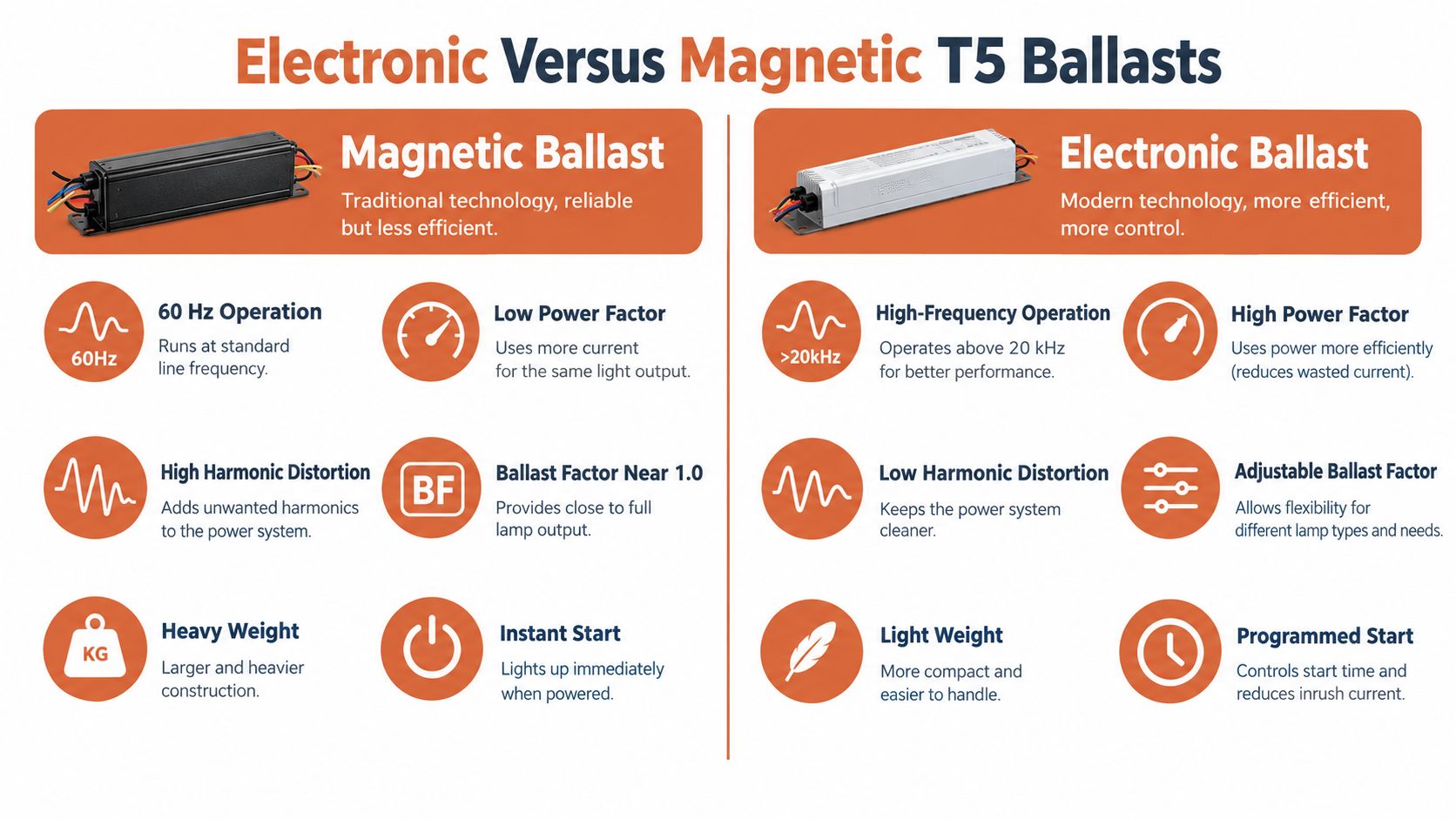
What the efficiency comparison actually means
T5 lamps were designed for high-frequency electronic ballasts rather than conventional magnetic arrangements. A Hong Kong government technical review of T5 lighting reports improved fluorescent efficacy above 10 kHz, ballast losses falling from 24 W to approximately 6 W in its cited twin-lamp circuit, and potential overall lighting-energy reductions of approximately 20% to 30% with a suitable luminaire.
Those are system-specific comparisons, not a savings guarantee for every replacement. In particular, reducing ballast losses isn't the same as reducing total fixture consumption by the same proportion.
Electronic vs Magnetic T5 Ballasts at a Glance
| Criterion | Electronic T5 Ballast | Magnetic T5 Ballast |
|---|---|---|
| Application suitability | Intended operating approach for conventional linear T5 systems | Don't assume suitability without explicit fixture and lamp documentation |
| Operating frequency | High-frequency operation specified by the product | Conventional magnetic operation isn't a substitute for the specified electronic system |
| Power factor | Verify the published value at the intended operating condition | Check the complete circuit and any compensation |
| Harmonic distortion | Require documented performance | Don't assign a value based only on ballast construction |
| Ballast factor | Match the lighting calculation | Don't assume an equivalent output |
| Starting method | Confirm the exact starting designation | Don't infer starting behavior from appearance |
| Weight and mounting | Verify dimensions, mounting, and thermal instructions | Neither weight nor mounting-hole alignment establishes compatibility |
The infographic's simplified categories shouldn't be treated as universal specifications. Magnetic doesn't automatically mean instant start, and electronic doesn't automatically mean dimmable or adjustable.
Power quality needs a datasheet
A Philips fluorescent-ballast technical specification illustrates the detail involved: programmed start, automatic restart, 120–277 V operation, frequency above 42 kHz, power factor above 0.98, total harmonic distortion below 10%, and lamp-current crest factor no higher than 1.7.
These aren't interchangeable terms. Power factor concerns the relationship between real and apparent power; harmonic distortion describes current-waveform distortion. Ballast factor concerns relative lamp output. A favorable value for one doesn't establish acceptable performance for the others.
For submittals, ask for those characteristics explicitly. A description that says only “electronic T5 ballast” leaves too much unresolved.
Identifying the Correct Ballast for a T5 Fixture
Start with the lamp marking, then reconcile it with the ballast and fixture labels. Don't begin with the replacement catalog and work backward toward something that looks plausible.
This field guide summarizes the identification sequence.
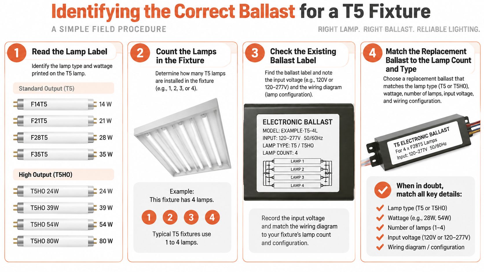
Read the complete lamp designation
Capture the entire marking, including the output-family designation. Relevant families include F14T5, F21T5, F28T5, F35T5, and T5HO lamps at 24, 39, 54, and 80 W, as reflected in T5 electronic-ballast application listings.
Don't shorten a high-output designation to “T5” on the purchase request. The supplier needs the actual lamp application, not just the tube family.
T5 tubes are 16 mm, or approximately 5/8 inch, in diameter and are approximately 50 mm shorter than commonly used T8 lamps, according to the Manual on Efficient Lighting. That dimensional difference matters when checking socket placement and fixture fit, but dimensions still don't establish electrical compatibility.
Match the operating configuration
Count the lamps connected to each ballast, rather than assuming the fixture's total lamp count equals its ballast configuration. Photograph any separate emergency equipment and identify which lamps it serves.
Next, verify supply voltage against the replacement's actual rating. The commercial voltage range discussed earlier doesn't mean every ballast accepts every supply within that range. A fixed-voltage product and a broadly rated product require different purchasing descriptions.
Starting method deserves its own check. Programmed start, rapid start, and instant start aren't procurement synonyms. Confirm the manufacturer's designation, then verify that the socket and wiring arrangements support it.
Ballast factor must also be deliberate. Published T5 ballast application and performance data identify 1.00 as common for T5HO applications and 0.95 or 1.15 for some T5HE applications; those latter values correspond to approximately 95% and 115% of reference lamp output.
A higher factor isn't automatically an upgrade. It can change input demand and thermal loading, so select the factor required by the lighting design.
Inspect the sockets before sending the request
Identify miniature-bipin arrangements, rotary-locking sockets where specified, and four-pin locking arrangements on applicable twin-tube lamps. Don't assume all small fluorescent sockets provide the same electrical connections.
Send the supplier a compact identification package:
- Lamp information: Full designation and clear photographs of the markings.
- Ballast information: Model, supported applications, lamp count, voltage, starting method, and ballast factor.
- Fixture information: Label, internal layout, mounting space, and socket photographs.
- Control information: Dimmer or control model, interface, and emergency-lighting arrangement.
- Wiring information: A legible diagram and photographs taken before disconnection.
If a label is unreadable, say so. A documented information gap is safer than a guessed specification.
Wiring and Installation Practices for T5 Ballasts
A replacement should begin with circuit isolation, not wire cutting. Qualified personnel should de-energize and lock out the circuit, verify the absence of voltage under the site's electrical-safety procedure, and identify any additional supply associated with emergency equipment.
Safe access comes before component replacement.
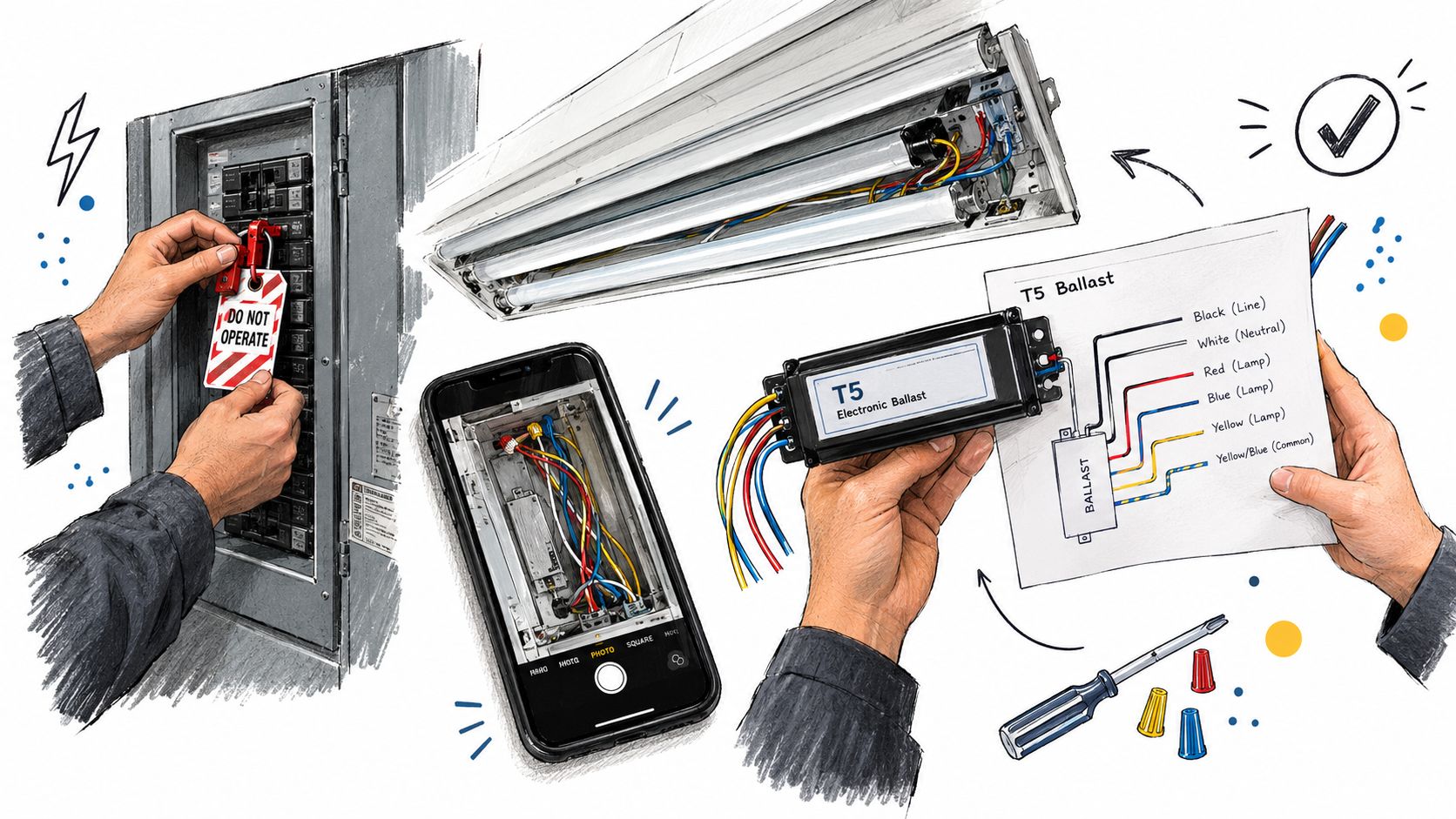
Follow the replacement diagram
Photograph the existing connections before disturbing them, but use those photographs as a record rather than an installation authority. Compare the replacement ballast's diagram with the actual fixture arrangement, including sockets, controls, and grounding.
Lutron's fluorescent dimming-system installation guidance identifies several important checks: fully seated lamps, correct socket selection, proper dimmed-hot and switched-hot connections, maximum lamp-wire length, and grounding.
- Socket connections: Confirm that the required contacts remain separate and intact.
- Control conductors: Identify conductors by function and the applicable diagram, not by an assumption about color.
- Lamp leads: Keep routing and length within the replacement manufacturer's limits.
- Grounding: Verify continuity through the intended grounding path before energizing.
Connector selection also needs application-specific review. The discussion of whether WAGO connectors are code approved is a useful starting point, but a connector still has to suit the conductor, enclosure, ratings, and installation instructions.
Preserve the intended heat path
Mount the ballast using the specified fixture-body arrangement. Where the manufacturer requires flush mounting, raised supports or attachment to a lamp-cover plate can defeat the intended thermal contact.
The heat-management principle is straightforward: restoring light doesn't prove that the ballast is operating under acceptable thermal conditions. Check the mounting interface and enclosure condition rather than judging the repair only from lamp operation.
Commissioning check: Accept the repair only after the fixture starts, operates, and responds to its controls as intended.
Use the video as supplementary installation context, not a substitute for the replacement's wiring diagram or the site's safety procedures.
After reassembly, check starting behavior, visible flicker, control response, dimming range where applicable, and abnormal heating. Confirm that lamps are fully locked into their sockets and that no lead has been pinched during closure.
Record the installed model and any approved changes in the maintenance file. That record prevents the next service call from beginning with the same identification problem.
Repair, Replace, or Retrofit to LED
A failed ballast creates a purchasing decision, but it should also trigger a lifecycle review. Repair is reasonable when it preserves a serviceable, supported system. It's less attractive when the facility is repeatedly investing labor in deteriorated equipment.
The available paths have different prerequisites.
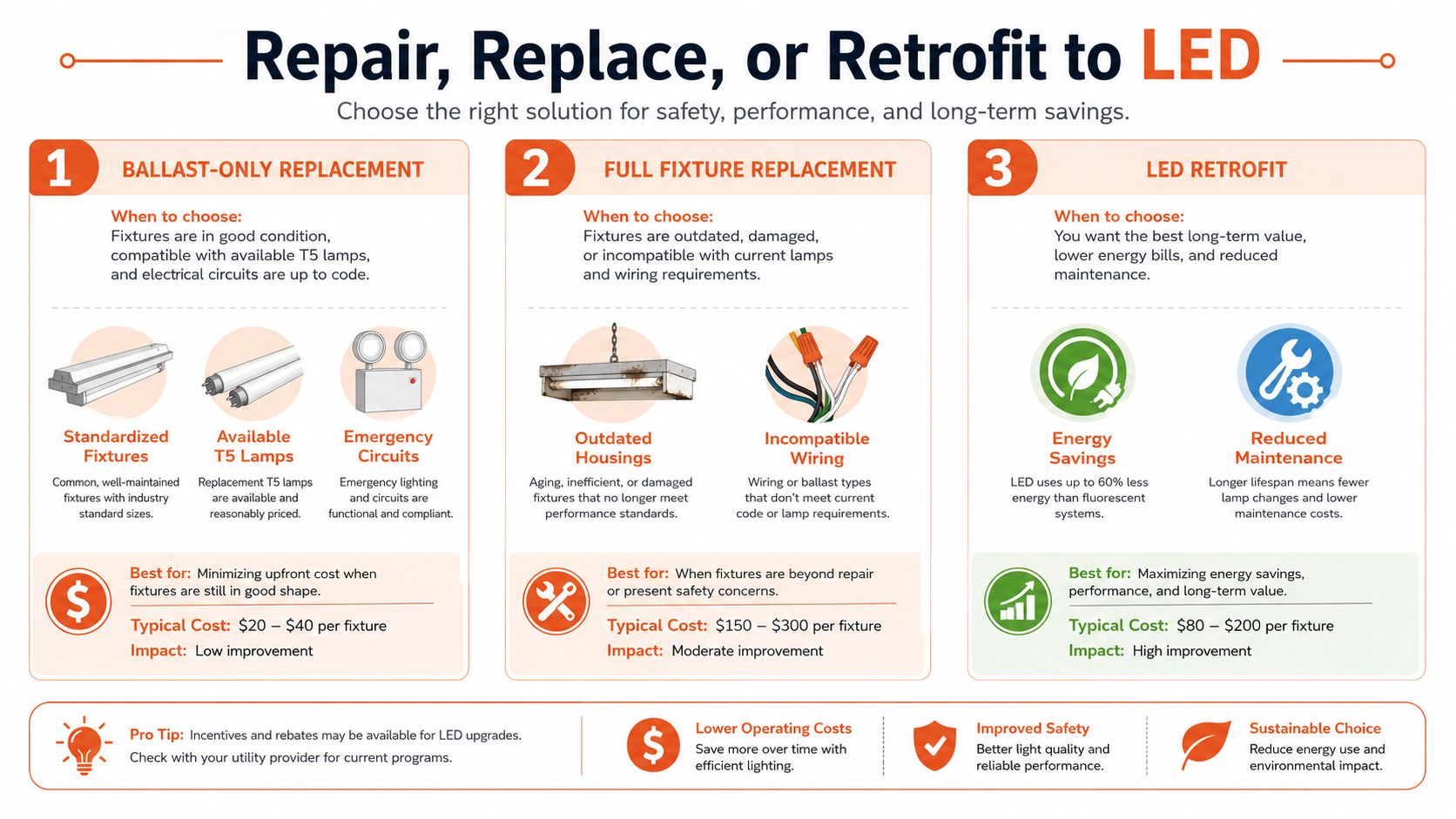
When retaining fluorescent makes sense
A ballast-only repair can be a practical choice where housings and optics remain sound, replacement lamps are available, and the existing emergency-lighting and control arrangements should remain unchanged. It can also suit a building awaiting a broader renovation.
That's a continuity decision, not necessarily the lowest lifecycle-cost decision. Include future lamp procurement, maintenance access, and mercury-containing-lamp handling in the evaluation.
Availability must be checked by market and lamp category. For example, the European lighting-industry lamp-exit timetable identifies February 25, 2023 as the market-placement cutoff for circular T5 fluorescent lamps under RoHS. That specific restriction shouldn't be generalized into a claim that every T5 lamp is prohibited everywhere.
Separate the LED options
For a ballast-compatible LED proposal, require the exact existing ballast model to be accepted by the LED manufacturer. For ballast bypass, require the specified rewiring arrangement and socket requirements. Neither option should proceed on physical fit alone.
Review the proposed retrofit's applicable UL listing, installation instructions, dimming behavior, and emergency-lighting compatibility. If the housing, wiring, or optical system needs substantial rehabilitation, include complete fixture replacement in the comparison.
A project-level LED lighting retrofit evaluation should compare installed scope and continuing maintenance, not just tube prices.
| Decision input | Ballast-only repair | LED tube retrofit | Full fixture replacement |
|---|---|---|---|
| Existing housing and optics | Retain if serviceable | Inspect suitability for reuse | Replace the assembly |
| Controls and emergency operation | Confirm restoration of existing functions | Require documented compatibility | Specify the required functions |
| Procurement | Confirm ballast and lamp support | Confirm tube, wiring, and compatibility documentation | Confirm complete luminaire submittal |
| Cost worksheet | Parts, access, labor, future relamping | Parts, conversion labor, controls work | Equipment, installation, controls work |
| Energy comparison | Actual system input | Proposed system input | Proposed luminaire input |
Populate the worksheet with your own fixture count, lamp cost, labor cost, operating schedule, and energy rate. Compare alternatives at acceptable illumination and control performance. Lower input power isn't a useful saving if the replacement no longer supports the work performed below it.
Troubleshooting Common T5 Ballast Failures
Symptoms narrow the investigation; they don't identify the failed component by themselves. A dark lamp can point to a lamp, socket, wiring, control, or supply problem before the ballast is condemned.
Use the identification record to establish what should be installed, then compare that with the fixture's condition.
No start or intermittent starting
Check the lamp application and starting arrangement against the approved configuration. With the circuit safely isolated, inspect lamp seating, socket contacts, damaged leads, and connections.
For applicable multi-lamp systems, Lutron's T5 socket and wiring guide requires sockets on yellow or blue-with-white-stripe leads to be connected in parallel rather than series. An incorrect connection can resemble a ballast failure, so verify topology before ordering another component.
| Symptom | Investigation priority | Verification |
|---|---|---|
| No start | Lamp condition, contacts, supply, starting configuration | Compare the installed assembly with its application diagram |
| Intermittent operation | Loose seating or connections | Inspect under isolation, then test after correction |
| Flicker or cycling | Connections and control compatibility | Compare behavior with the approved operating configuration |
| Unexpected light output | Lamp designation and specified ballast factor | Compare the installed label with the lighting schedule |
Flicker, dimming instability, and noise
If the problem occurs only during dimming, investigate the control interface and operating configuration rather than immediately replacing the ballast. Don't attempt to solve a control mismatch by changing lamp wattage.
Buzzing or ticking warrants inspection, but the sound alone doesn't establish harmonic interaction or a failed internal component. Where several fixtures behave abnormally together, evaluate the shared supply and controls; the discussion of power quality issues provides useful context for that broader investigation.
Heat, odor, and immediate isolation
Fluorescent ballasts can remain energized and reach approximately 150 °F even when the fixture is switched off; buzzing, ticking, vibration, melting-plastic or ozone odors, charring, and deformation are warning indicators requiring isolation and investigation, as described in fluorescent-lighting loss-prevention guidance.
A wall switch in the off position is not a safe-isolation procedure.
Smoke, a melted housing, or charring takes the fixture out of routine troubleshooting. Disconnect the affected equipment, preserve required illumination through an approved temporary arrangement, and investigate the damage before returning it to service.
Don't open the ballast or infer internal capacitor temperature from the switch position or exterior appearance. Follow the manufacturer's handling instructions and site isolation procedure. Review application loading, thermal contact, and obstructed ventilation without energizing visibly damaged equipment merely to reproduce the fault.
Sourcing, Compliance, and Next Steps for T5 Projects
Procurement should receive a verified application package, not just a photograph accompanied by “send an equivalent.” Include fixture quantities, full lamp designations, existing ballast labels, supply information, controls, emergency arrangements, and the required repair or retrofit scope.
Define documentation before approving alternatives
A federal fluorescent-luminaire specification requires nationally recognized testing-laboratory listing, UL 935 compliance, and ANSI C82.1 compliance for its covered T4/T5 compact-fluorescent ballasts. Apply those requirements within their stated scope rather than treating that document as a universal specification for every linear T5 installation.
For federal procurement, identify any Buy American Act or Trade Agreements Act requirements in the contract and request product-specific documentation.
- Technical approval: Require the alternate's application data, wiring diagram, and relevant compliance documents.
- Supply planning: Confirm availability and identify who approves substitutions if lead times change.
- Lifecycle alignment: Specify whether the purchase supports continued fluorescent maintenance or a planned conversion.
A distributor can review the BOM, coordinate manufacturer questions, and identify hard-to-source or alternate components. Engineering approval still belongs with the responsible project authority. Selecting a ballast for T5 equipment works best when sourcing and technical acceptance use the same documented requirements.
ATEK Distribution offers BOM review, hard-to-source component sourcing, manufacturer coordination, and compliance-documentation support for T5 repairs and lighting upgrades. Visit ATEK Distribution with your lamp markings, ballast-label photographs, wiring diagram, and project specification to request availability, alternate-part identification, or project-specific procurement assistance.