
A crimped splice can look finished when the panel door closes and still become the source of a difficult callback. The usual causes aren't mysterious: the installer used the wrong tool, stopped before the controlled cycle released, stripped the conductor too far, or selected a connector for a different wire combination. Permanent connections demand more discipline than a quick squeeze with whatever tool is already on the belt.
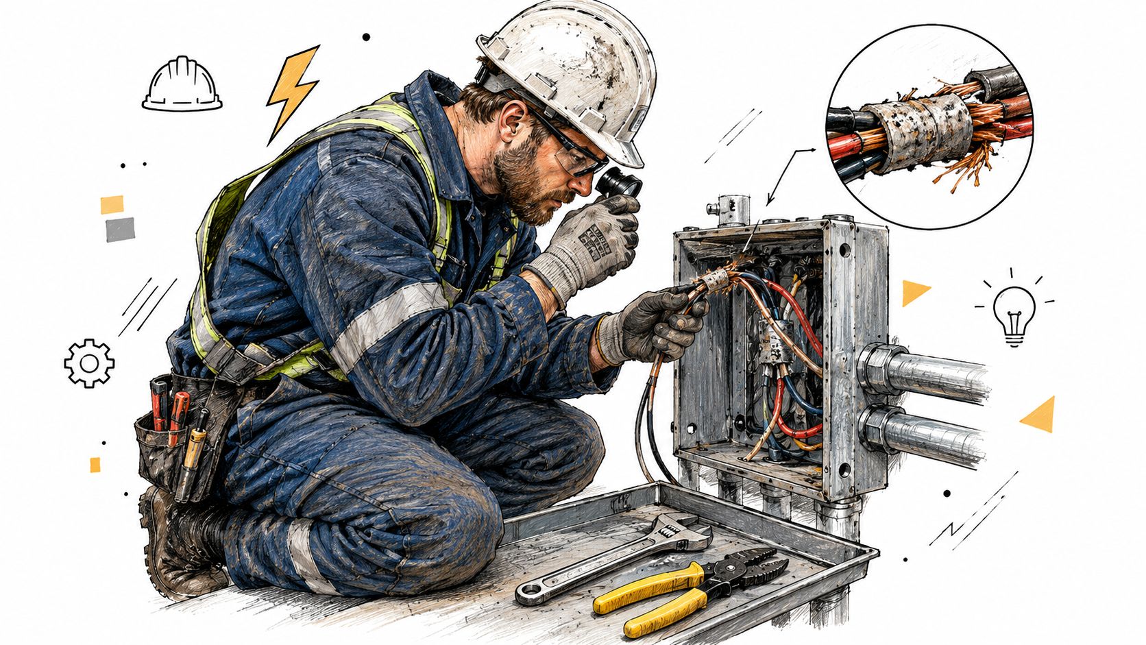
Table of Contents
- Why Buchanan Crimp Connectors Matter in Industrial Electrical Work
- Crimp Connectors vs Wire Nuts vs Soldered Splices
- Buchanan Crimp Splice Families and Specifications
- Proper Crimping Procedure and Tool Selection
- Why Generic Lineman Pliers Undermine Crimp Quality
- Matching Connectors to Circuits and Environments
- Practical Installation Examples by Application
- Compliance Context and UL CSA Listing Guidance
- Troubleshooting Common Crimp Problems
- How to Choose the Right Buchanan Crimp Connector
Why Buchanan Crimp Connectors Matter in Industrial Electrical Work
Buchanan crimp connectors are permanent, pressure-type splice devices. Unlike a removable terminal, the connector is compressed around the conductors with a dedicated tool, creating a mechanical and electrical joint intended to stay in place. That makes the connector useful where vibration, limited access, or the need for a compact splice makes other methods less practical.
Buchanan's tooling history reaches back to the formalization of high-reliability crimping. The company introduced a 4-indent crimp tool with a ratchet in 1960, while the first crimp tool standard, MS3191-1, was published in 1963. MIL-T-22520 followed in 1969, later becoming MIL-C-22520 and then MIL-DTL-22520, as documented in this high-reliability electrical tooling guide. Buchanan was also listed in the first Qualified Products Listing for QPL-22520 in 1969, placing the brand within the early standardized crimp-tooling ecosystem.
What the method changes in the field
A wire nut is convenient and readily removable. A soldered splice can provide a sound electrical joint when the process, support, insulation, and applicable requirements are all controlled. A Buchanan crimp splice takes a different route. It relies on a correctly sized sleeve, the right conductor combination, and repeatable compression.
That repeatability is why tooling matters more than the connector's unit price. A government technical report estimated that about 70 billion crimp-type wire terminations were used annually in the United States, and its collected field data recorded no failures in the observed set. The report concluded that field failures of crimp connections were rare, supporting the method's broad use in demanding electrical and electronic applications. Read the technical report on crimp termination reliability for the historical context.
This guide focuses on the 2006S family and 2011S class, their conductor ranges, the Buchanan C24 and P24 tools, installation checks, and the situations where generic pliers are a poor substitute. That information helps contractors, panel builders, engineers, and buyers make a defensible selection before material reaches the jobsite.
Crimp Connectors vs Wire Nuts vs Soldered Splices
The right termination method depends on more than speed. The crew has to consider vibration, access for future work, conductor compatibility, enclosure space, and the documentation required for approval.
| Termination type | Vibration resistance | Rework capability | Installation speed | Best industrial use case |
|---|---|---|---|---|
| Buchanan crimp connector | High when correctly matched and compressed with the specified tool | Low after crimping | Fast after the process is established | Permanent splices in equipment, panels, utility, and industrial wiring |
| Wire nut | Suitable only where the connector and application permit it | High | Fast | Accessible junctions where removable splicing is appropriate |
| Soldered splice | Depends heavily on workmanship, mechanical support, and environment | Low to moderate | Slower | Specialized electronics or assemblies designed around soldering |
Wire nuts remain useful where technicians need to open a junction repeatedly, provided the connector is listed and suitable for the conductors and enclosure. They can be a poor choice in locations where vibration, movement, or limited inspection access makes loosening and conductor disturbance a concern. Solder can also be appropriate, but solder alone shouldn't be treated as a mechanical strain-relief system for ordinary building or industrial wiring.
For a broader comparison of removable twist-on methods and push-in products, see this comparison of push-in connectors and wire nuts. The point isn't that one method wins everywhere. The point is to match the termination to the circuit's service conditions and the approved installation method.
Field rule: If the splice is intended to remain in place and the conductors will see vibration or movement, select the connector and tool as one installation system.
A Buchanan crimp splice makes the most sense when the contractor wants a compact, permanent connection and can control the conductor range, strip length, tool selection, and inspection process. It isn't the answer for every repair. It is a strong option when rework is unlikely and consistent compression is more valuable than easy removal.
Buchanan Crimp Splice Families and Specifications
The two families most relevant to common Buchanan splice-cap work are the 2006S family and the 2011S class. They aren't interchangeable just because both are copper crimp connectors. The wire range and approved combinations determine which one belongs on the bill of materials.
| Connector family | Conductor range | Voltage rating | Key compliance note |
|---|---|---|---|
| Buchanan 2006S | 18 to 10 AWG solid copper | 600 VAC | Listings note UL 486C and CSA C22.2 #188 |
| Buchanan 2011S / 2011SB | 14 to 4 AWG | 600 V AC | Intended for permanent pressure-type connections, with published wire-combination limits |
The 2006S family is specified for 18 to 10 AWG solid copper conductors, with a 600 VAC rating and a maximum operating temperature of 221 °F. Its approximate physical envelope is 0.211 inches in diameter by 0.425 inches in length. The product listing identifies 2006S specifications and compliance details, including UL 486C and CSA C22.2 #188.
That compact size can help in a crowded enclosure, but the small body doesn't eliminate the need to confirm conductor count and combination. Use the listed combination, not just the nominal gauge, when ordering.
Where the larger family fits
The 2011S and 2011SB class extends the range to 14 through 4 AWG. Listings describe the products as fast, permanent, pressure-type connections and identify compatibility with the Buchanan C24 crimp tool. The solid copper sleeve is described as requiring less crimping pressure and offering improved corrosion resistance in harsh environments, a useful characteristic for vibration-prone OEM, utility, and facility wiring. Review the 2011SB product details before approving a substitute.
The 2011S listing shows approved combinations including two 10 AWG conductors at the minimum and two 6 AWG conductors at the maximum, with the product rated for 600 V AC. Those details appear in the 2011S wire-combination listing.
Don't choose the larger body only because it feels more substantial. Choose the family that matches the conductor material, gauge, count, and approved combination. For copper solid conductors, the sleeve and tool pairing must agree with the product documentation.
Proper Crimping Procedure and Tool Selection
A reliable splice starts before the tool touches the connector. Confirm the connector family, conductor combination, and tool compatibility against the product documentation. Buchanan splice-cap listings identify the C24 or P24 pres-SURE tool for applicable models, including the 2006S, 2008S, and 2011S families.
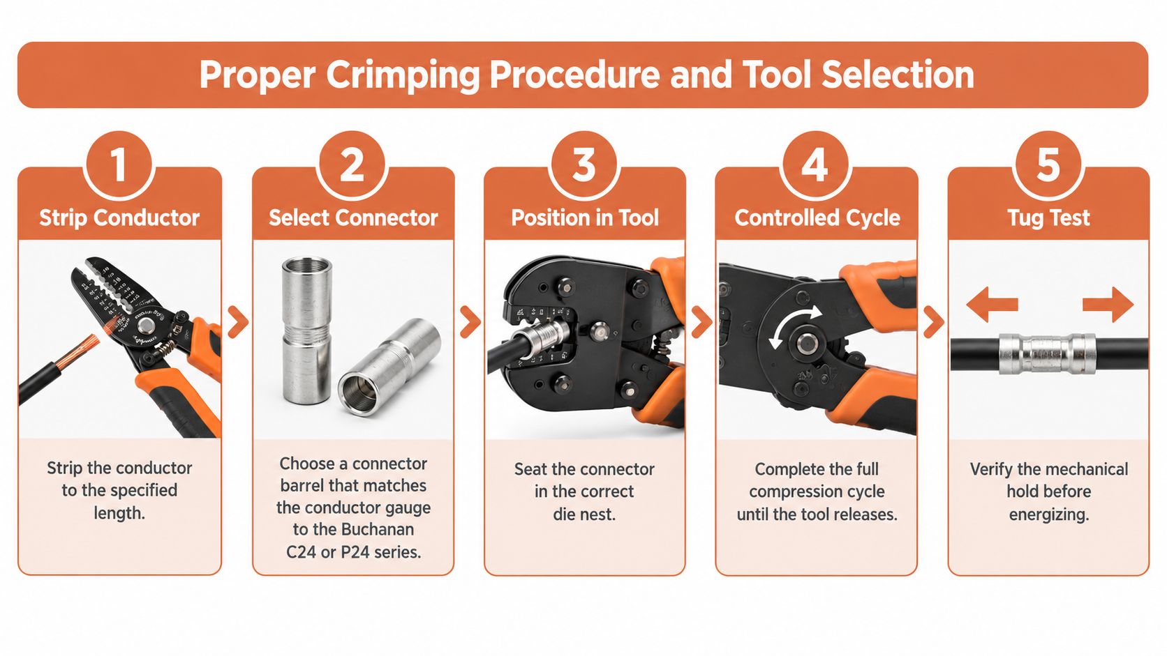
A controlled installation sequence
-
Strip the conductor. Remove insulation to the specified strip length, commonly around 3/4 inch for the listed Buchanan splice-cap applications. Don't nick or reduce the copper strands, and don't leave excess bare conductor outside the cap.
-
Select the connector. Match the sleeve to the conductor material, gauge, and number of wires. For the families covered here, the relevant listings specify solid copper conductors. A connector that fits physically can still be wrong electrically or mechanically.
-
Insert the conductors fully. Bring the conductors together, insert them into the sleeve, and verify that the ends reach the intended insertion depth. Keep insulation out of the crimp area while preventing unnecessary bare copper from extending beyond the finished splice.
-
Seat the connector in the correct tool position. Place the splice cap in the appropriate C24 or P24 die position and engage the tool's latch or controlled-cycle mechanism. The latch setting controls how the tool completes compression, so don't substitute a guessed position.
-
Complete the cycle and inspect. Close the tool until the mechanism releases according to its designed cycle. Then perform the prescribed mechanical check, including a firm tug test, and flush-cut any protruding conductor ends where the product instructions call for it.
The cable ferrule crimping guide covers the same broader principle, namely that conductor preparation, die selection, and complete tool operation determine the finished connection. A partial squeeze isn't a controlled crimp. If the tool won't complete its cycle, remove the assembly and find the cause instead of forcing the handles or accepting the result.
Why Generic Lineman Pliers Undermine Crimp Quality
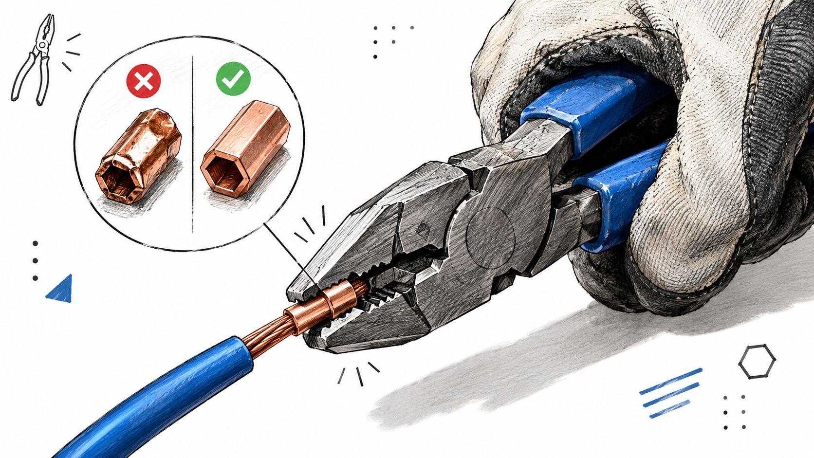
Lineman pliers are excellent for cutting, holding, twisting, and many general electrical tasks. They aren't a controlled-cycle crimper. The jaws apply force according to hand position and mechanical advantage, not according to a defined compression sequence and die geometry.
A splice made with generic pliers may appear tight while leaving uneven pressure around the sleeve. One side can be crushed more than the other, the conductor can shift inside the barrel, or the sleeve can be distorted without producing a stable mechanical hold. Visual inspection alone won't reliably distinguish a uniform crimp from a loosely formed one.
The practical issue is variation. Two installers can use the same pliers and produce different results, while one installer can produce different results as hand position, access, fatigue, and conductor arrangement change. A controlled-cycle tool reduces those variables by guiding the compression and requiring completion of the cycle before release.
What the shortcut costs
The common defense is that pliers are faster. They may be faster for one isolated squeeze, but rework, inspection questions, and inconsistent connections erase that advantage quickly on a production run. A distributor description specifically contrasts controlled-cycle uniformity with plier-made crimps, which is why the role of a dedicated PAT750Li crimper matters when the connector and application call for a different compression system.
For Buchanan splice caps, use the specified Buchanan C24 or P24 tool where the product documentation identifies it. Don't assume another crimper, a different die, or ordinary pliers will produce an equivalent result.
The following demonstration is useful for discussing tool technique with a crew, but it doesn't replace the connector manufacturer's installation requirements.
Matching Connectors to Circuits and Environments
Connector selection should follow the circuit, not the other way around. A product's voltage rating, temperature limit, conductor range, and environmental suitability all have to agree with the installation.
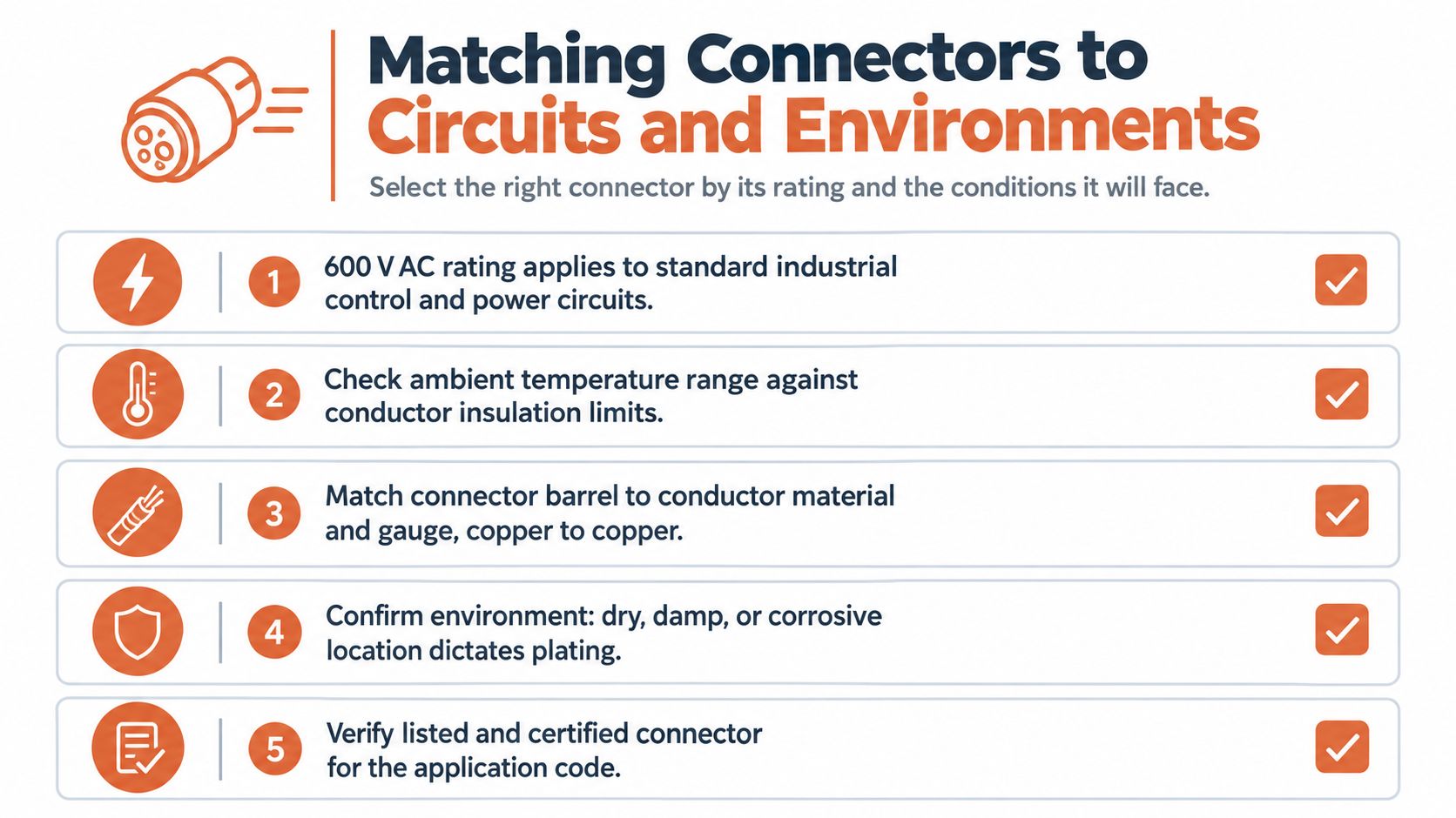
Use this checklist during BOM review:
-
Confirm voltage. The 2006S and 2011S listings identify a 600 VAC or 600 V AC rating. That rating must still be appropriate for the complete circuit and installation.
-
Check temperature. The 2006S listing specifies a maximum operating temperature of 221 °F. Compare that limit with the actual location, nearby heat sources, conductor insulation, and enclosure conditions before placing a splice near a hot component.
-
Match conductor material and gauge. The covered families are listed for solid copper conductors. Verify gauge, conductor count, and the approved combination. Never treat a broad gauge range as permission to combine any wires within it.
-
Evaluate the environment. Vibration, moisture, chemicals, and corrosion exposure influence the connector and enclosure decision. The 2011S class is described as offering better corrosion resistance through its solid copper sleeve, but that doesn't remove the need for suitable enclosure and installation practices.
-
Verify documentation. Confirm the product listing, tool pairing, installation instructions, and project requirements before approving a connector or alternate.
For procurement teams, this checklist also helps separate a technically acceptable alternate from a visually similar part. If the original connector is unavailable, compare the conductor range, wire combination, rating, material, dimensions, listing, and required tool before requesting approval.
Practical Installation Examples by Application
A control-panel splice usually brings tight space and a high expectation for orderly workmanship. A 2006S-family connector may suit the conductor range when the wiring uses compatible solid copper conductors, but the installer still has to maintain the specified strip length and keep the completed splice clear of terminal blocks, sharp edges, and moving hardware. The C24 tool should be available at the panel, not improvised after the conductors are already prepared.
Branch-circuit and equipment wiring can involve larger conductors and greater mechanical exposure. The 2011S class covers larger wire sizes than the 2006S family, including published combinations such as two 10 AWG conductors at the minimum and two 6 AWG conductors at the maximum. That makes it a more relevant candidate for larger equipment or branch-circuit splicing, subject to the circuit design and applicable requirements.
Different job conditions, same quality controls
In an OEM panel assembly, repeatability is often more important than field convenience. Establish the approved connector and tool at the work instruction, train assemblers on the complete cycle, and inspect sample crimps before production continues. A connector that passes a quick visual check but spins on the conductor should be rejected.
A utility or facility repair can add vibration, restricted access, and pressure to restore service quickly. Those conditions are exactly when generic pliers become tempting. Prepare the conductors carefully, use the specified tool, verify the mechanical hold, and leave enough room for inspection and future maintenance.
For each application, the load and circuit design remain the engineer's responsibility. The crimp connector only addresses the splice. It doesn't correct an undersized conductor, poor routing, inadequate overcurrent protection, or an enclosure problem.
Compliance Context and UL CSA Listing Guidance
The UL 486C and CSA C22.2 #188 references associated with the 2006S listings indicate that the splice devices have been evaluated within the scope of those standards. For a contractor or inspector, that documentation supports the use of a listed permanent splice device when the product is installed within its ratings and instructions.
A listing isn't a blanket approval for every circuit. It doesn't replace conductor sizing, overcurrent protection, enclosure requirements, accessibility decisions, or the applicable NEC provisions for the installation. It also doesn't make an unapproved tool acceptable. The product, conductor combination, crimp tool, and installation method must remain aligned.
What to retain in the project file
During submittal review, request the current product data, listing information, installation instructions, and any tool compatibility documentation. Procurement should preserve those records with the BOM, especially when a project uses an alternate connector because of availability.
The product listing cited for the 2006S family places it in the common North American permanent splice category for low-voltage building and industrial wiring. That context is useful, but the authority having jurisdiction and the project's engineering requirements still control acceptance.
Inspectors should look for more than a familiar brand name. Check the connector family, conductor range, visible crimp, insulation clearance, and evidence that the installer used the specified process. A compliant component can still be installed incorrectly.
Troubleshooting Common Crimp Problems
Most crimp defects leave a physical clue. The key is to stop before energization or panel shipment, identify the cause, and replace the defective splice rather than trying to rescue a damaged sleeve.
| Symptom | Likely cause | Corrective action |
|---|---|---|
| Sleeve spins or feels loose | Wrong connector range, incomplete cycle, or insufficient insertion | Cut out the splice and remake it with the approved family and complete tool cycle |
| Sleeve is flattened or split | Excessive force, wrong die, or incorrect tool | Discard the damaged connector and verify the C24 or P24 position |
| Bare copper extends too far | Strip length was excessive | Remove and restrip to the specified length |
| Insulation is inside the crimp area | Strip length was too short or conductor wasn't seated | Replace the splice and confirm full conductor insertion |
| Indent is off-center | Connector wasn't seated correctly in the tool | Reposition the connector and use the correct tool nest |
| Conductor pulls free | Wrong wire combination or incomplete compression | Replace the assembly, then verify the listing and cycle completion |
Don't squeeze a loose connector again with pliers. That may hide the symptom while leaving the sleeve with an unknown compression profile. Permanent splices should be replaced when the crimp is suspect.
A tug test is useful for finding a weak mechanical hold, but it isn't a substitute for correct tool selection or product instructions. Inspectors and foremen should also look for nicked copper, damaged insulation, exposed conductor beyond the finished cap, and a connector body that has been crushed out of shape.
How to Choose the Right Buchanan Crimp Connector
Start with the conductor combination, not the connector package. Record the wire material, solid or stranded construction as applicable to the listing, gauge, number of conductors, and circuit rating. Then narrow the choice to a family whose published range and combination cover that arrangement.
Use the 2006S family when the documented application falls within 18 to 10 AWG solid copper, the connector's 600 VAC rating and 221 °F maximum operating temperature suit the installation, and the physical envelope works in the enclosure. Use the 2011S class for combinations within 14 to 4 AWG, including the published larger-conductor combinations, when the circuit and installation requirements support that choice.
A job-ready selection check
-
Validate the wire combination. Gauge alone isn't enough. Check conductor count and the manufacturer's published minimum and maximum combinations.
-
Confirm the ratings. Review voltage and temperature against the actual circuit and environment, not just the nominal project category.
-
Pair the connector with the tool. Confirm whether the job calls for a Buchanan C24 or P24 pres-SURE tool, and verify the correct latch or die position.
-
Plan the installation. Make sure the crew has stripping tools, the dedicated crimper, space for a complete cycle, and a way to inspect and test the finished splice.
-
Document alternates. When supply constraints force a substitution, compare listing, material, dimensions, conductor range, wire combination, and tooling before submitting it for approval.
That process gives engineers and contractors a clear basis for procurement decisions. It also helps purchasing teams avoid a common mistake, ordering a connector that fits the wire diameter but doesn't match the approved combination or available tool.
ATEK Distribution can help with connector and crimper sourcing, BOM review, product submittals, compliance documentation, and approved alternatives when an industrial project has a difficult lead-time or availability problem. Contact ATEK Distribution with the connector family, conductor combination, tool requirement, and project documentation so the sourcing team can help verify the material before it reaches the field.