
You're reviewing a one-line, the cable schedule is still moving, and someone has already asked for a wire cable tray part number. That's the wrong starting point. The tray decision should follow the run, not precede it: classify the cables and environment, calculate the working load, select the tray family, then lay out supports, fittings, bonding, and future access.
Wire mesh tray often earns the first look on indoor industrial, communications, and data-center runs because installers can load cables from the side, inspect the run quickly, and make field changes without threading cables through a closed raceway. But it isn't a universal answer. Heavy feeders, long unsupported spans, severe corrosion, and high concentrated loads can push the design toward ladder, solid-bottom, or another tray system.
Table of Contents
- Why Wire Cable Trays Are the First Decision on Most Industrial Runs
- Tray Types Compared for Real-World Applications
- Load Classes and Support Span According to NEMA VE 1
- Wire Mesh Cable Tray Specifications for Data and Power
- Support Layout, Hangers, and Span Planning
- Bonding and Grounding Requirements for Metallic Trays
- Routing, Fittings, and Installation Sequence
- Quick Reference for Wire Cable Tray Selection
Why Wire Cable Trays Are the First Decision on Most Industrial Runs
An engineer standing over a one-line usually needs to answer four questions in order:
- What is in the run? Separate power, control, communications, fiber, and special-purpose circuits by cable construction, voltage, heat, and required separation.
- What load will the tray carry? Use the cable schedule, not the empty-tray appearance.
- Which tray family fits the work? Wire mesh, ladder, ventilated trough, and solid bottom solve different problems.
- How will the system be supported and bonded? A correctly selected tray can still fail inspection or field acceptance if the support and grounding plan is incomplete.
Wire cable trays are particularly effective for indoor distribution runs with frequent cable additions. The open grid lets an installer drop or side-load cables at accessible points instead of pulling every new cable through a continuous enclosure. The same structure promotes airflow around the cable bundle, which is useful where power and communications cables share a managed corridor under the project's separation requirements.
The tray's low dead weight also simplifies bracket and trapeze work compared with heavier enclosed systems. That advantage matters in congested electrical rooms, overhead utility corridors, and data-center spaces where access is more valuable than a perfectly enclosed route. The open construction makes visual inspection easier too. A technician can see cable identification, bend conditions, unused capacity, and damaged insulation without removing a cover.
Know when mesh has lost the argument
Wire mesh becomes less attractive as the run becomes structurally demanding or environmentally aggressive. Heavy feeders may need the greater stiffness and deeper support structure of ladder tray. Long spans can require more supports than the project allows. Outdoor or corrosive environments may call for a material and finish selected specifically for exposure rather than a standard indoor wire product.
The category is formally standardized. In North America, metal cable tray systems are covered by NEMA VE 1 and installation guidance in NEMA VE 2, while IEC 61537 provides the international reference for cable tray and ladder systems, including wire mesh trays. NEMA VE 2 was later renumbered as NEMA BI 50016-2024, identified as the fourth edition, which reflects continued formal development rather than an informal product category.
Practical rule: Don't select mesh because it is easy to install. Select it when its access, ventilation, and changeability solve the actual constraints of the run.
Tray Types Compared for Real-World Applications
The fastest way to choose a tray family is to compare each one against the same field questions: how cables enter and leave, how the tray manages heat, how fittings affect the route, and whether the structure suits the expected span and load.
| Tray Family | Cable Exit | Ventilation | Typical Span | Best Application |
|---|---|---|---|---|
| Ladder tray | Cable exits between rungs or over the side | Very good | Often preferred for longer, heavier runs | Large feeders, industrial power distribution, and runs requiring strong support |
| Ventilated trough | Side or top exit through perforated construction | Good | Moderate, dependent on load and profile | Control wiring, instrumentation, and general industrial distribution |
| Solid-bottom tray | Exit requires fittings, drops, or planned openings | Limited compared with open tray | Moderate, subject to loading and support design | EMI-sensitive routing, drip protection, and enclosed cable environments |
| Wire mesh tray | Side loading and exit through the grid | Very good | Moderate, dependent on product rating and support spacing | Data, communications, control, and mixed-power indoor runs with frequent changes |
Where each tray family wins
Ladder tray wins when the cable mass is high and the route needs strong longitudinal support. It also provides straightforward access for large cables, but the rung arrangement can make small cable management and frequent branch-offs less tidy.
Ventilated trough is a practical middle ground for control and instrumentation. It offers a more continuous base than mesh while retaining ventilation. It can lose time on dense branch routing because installers may need more fittings or field openings.
Solid-bottom tray earns its place where cable protection, falling debris, or electromagnetic considerations matter more than maximum airflow. The trade-off is heat management and less convenient side loading. It shouldn't be treated as a default substitute for mesh in a high-change installation.
Wire mesh is usually the efficient choice for communications, fiber, and indoor mixed services. A broader cable-management overview, including how organized routing supports safer installations, is available in safer homes cable management. The link is residentially oriented, but the routing principles around access and organization transfer well to industrial planning.
For a mixed-services corridor, use mesh where the run is light to moderate and changes are expected. Reserve ladder for the feeder route, use trough for control groups that benefit from a continuous base, and use solid bottom only where its protection or shielding benefit justifies reduced ventilation.
Load Classes and Support Span According to NEMA VE 1
A tray rating becomes useful only after the run is classified and the cable schedule is calculated. Determine the installed cable weight per foot, identify the proposed support span, then select a tray class rated for the working load at that span.
NEMA VE 1 commonly uses these working-load designations: Class A is 50 lb/ft, Class B is 75 lb/ft, and Class C is 100 lb/ft. The class is tied to both load and support span, so one tray profile can have different ratings as the distance between supports changes. The Eaton NEMA-based cable tray specification gives a 20C tray example, rated for a 20-foot support span at 100 lb/ft.
| NEMA Class | Working Load (lb/ft) | Typical Span (ft) | Deflection Limit |
|---|---|---|---|
| A | 50 | Product-specific, verify the tested rating | Verify the manufacturer's NEMA data |
| B | 75 | Product-specific, verify the tested rating | Verify the manufacturer's NEMA data |
| C | 100 | 20-foot example for 20C | Verify the manufacturer's NEMA data |
Size the tray with this calculation:
Required tray capacity = calculated cable load per foot ÷ selected allowable load fraction
The allowable load fraction is the portion of the published working load that the project permits. For example, using 0.8 reserves capacity for future additions. If the calculated cable load is 40 lb/ft and the selected fraction is 0.8, the required published capacity is 50 lb/ft, which corresponds to the Class A working-load value before checking the manufacturer's span and deflection data.
Use the rating for the exact tray width, depth, construction, and support span. Do not divide total project cable weight by the route length unless the load is genuinely distributed along that route. A concentrated bundle at a drop, reducer, splice, or fitting can control the design even when the straight section passes its load check.
Published class versus installed working load
The working-load value covers the cable load within the tested arrangement. It is not a target for filling the tray to the catalog limit. Future additions, uneven distribution, splice locations, and fittings reduce the margin available in the field.
Verify the manufacturer's tested span and deflection data during submittal review. Project documents may require a welded wire pattern to carry a uniformly distributed load over a defined span, tested as a simple span to NEMA VE 1. That requirement links the tray's published class to the actual support arrangement, rather than treating the class as a standalone product label.
Wire Mesh Cable Tray Specifications for Data and Power
Specify wire mesh tray by the conditions it must handle, not by its appearance. Classify the route first as data, control, or power. Then check cable size, heat dissipation, bend radius, environmental exposure, and required accessories before selecting the mesh, depth, width, finish, and support arrangement.
For communications work, confirm the opening against the selected manufacturer's cut sheet. A 3.7-inch by 5-inch welded wire pattern retains small cables differently from a 2-inch by 4-inch grid, and the opening can affect which divider strips and other accessories fit. The Panduit cable-tray specification illustrates the type of construction detail that belongs in a project specification. A denser grid can retain small cables more effectively, while a more open grid improves access and may provide fewer surfaces for dust to collect.
Construction details that affect installation
Project specifications may call for 4 mm or 5 mm wire, depths from 30 mm through 150 mm, and widths from 50 mm through 600 mm. Confirm each dimension against the manufacturer's product data. Nominal width and depth alone do not establish load capacity, deflection, or accessory compatibility.
The welded joint affects field work. T-welded and resistance-welded construction can respond differently when an installer cuts a side opening or modifies a section. Any cutout must protect the cables and retain joint strength. Remove burrs and sharp projections, and provide support near modified areas rather than relying on an improvised field cut.
| Depth | Width Range | Wire Diameter | Mesh Pattern | Typical Finish | Application |
|---|---|---|---|---|---|
| 30 to 150 mm | 50 to 600 mm | 4 or 5 mm, where specified | Open grid selected for cable size and retention | Zinc-plated mild steel or stainless steel | Indoor data, control, and power-support routes |
Zinc-plated mild steel is commonly specified indoors. For corrosive exposure, evaluate 304 or 316 stainless steel against the actual environment. IEC 61537 provides the performance framework for cable tray systems, but the manufacturer must still identify corrosion classification and environmental suitability. Do not infer a C1 through C5 rating from the metal name alone.
Set cable fill to preserve space for heat dissipation, bends, drops, and future changes. Include Category 6A and single-mode fiber bend-radius requirements in the tray layout. Show splices, drop-outs, divider strips, and transitions on the plan so installers do not have to improvise around a loaded bundle.
For communications infrastructure sourcing, see ATEK's data and telecommunications infrastructure category.
Support Layout, Hangers, and Span Planning
Tray selection ends where support engineering begins. A wire mesh tray can meet its product rating and still produce a poor installation if the supports are too far apart, the bracket is undersized, or a fitting carries a load it was never intended to carry.
Common support arrangements include cantilever brackets, trapeze assemblies, and direct-mount brackets. Strut channel systems using 41 by 41 mm or 41 by 21 mm profiles can work with standard fittings, but the complete assembly must be checked for the tray width, cable load, bracket projection, and anchor condition.
Match the support to the load
Use the tested support spacing for the selected NEMA class and product. Light Class A runs may use shorter support spacing such as 1.5 m, while Class C applications may use 2.4 to 3.0 m spacing when the specific tray rating permits it. The field acceptance criterion is the manufacturer's stated deflection requirement, not a visual judgment made from the floor.
Provide additional support at reducers, tees, crosses, elbows, vertical transitions, and locations where cable bundles enter or leave the tray. Concentrated loads can control even when the straight section carries a modest uniform load. Expansion fittings and thermal transitions also need a planned location, with bonding continuity maintained across any movement joint.
Worked layout example
Consider a 9 m straight run of 300 mm wire mesh tray carrying 30 kg/m. The total distributed cable load is 270 kg across the run. That figure alone doesn't select the tray or support spacing, because the engineer must convert the project load to the applicable product rating and verify whether the stated load is uniform, whether accessories add weight, and whether the selected support centers are tested.
If the approved product allows the chosen span, lay out supports at the manufacturer's centers and place end supports so the tray overhang remains within the installation instructions. A 9 m route may require multiple support bays rather than a support at each end. Select a cantilever or trapeze bracket based on the 300 mm width, the total reaction at each support, and the structure available above the route.
Use conduit, raceway, and cable support products when coordinating the tray with adjacent raceway and support hardware. On site, verify anchor installation, bracket torque, tray level, splice alignment, and clearance from mechanical and process piping before the cable crew arrives.
Bonding and Grounding Requirements for Metallic Trays
A metallic tray is part of the electrical installation, not just a support shelf. The design must establish mechanical continuity, bonding continuity, and a documented grounding path under the applicable project requirements.
NEMA VE 2 states that metallic cable trays should be bonded to building steel and earth as supplemental grounding for ground-fault protection and signal-grounding noise prevention. It also identifies a maximum bonding interval of 18 m, or 60 ft, between bonded sections, as described in the NEMA VE 2 installation guidance.
The tray is not automatically the EGC
NEC guidance summarized by the Electrical Association grounding presentation permits a metallic cable tray to serve as an equipment grounding conductor only when continuous maintenance and supervision ensure that qualified people service the installed system and the applicable bonding provisions are satisfied. That condition is often misunderstood. Many industrial specifications require a separate green equipment grounding conductor even where the tray could qualify under the applicable code conditions.
Where a separate bonding jumper is required, size it under the applicable NEC rules, including the largest circuit overcurrent device used for the calculation. Provide jumpers across expansion fittings, flexible sections, and discontinuous segments. Use listed grounding clamps and listed splicers, and remove paint or nonconductive finish at contact points where the listed hardware requires metal-to-metal continuity.
Don't treat a bolted splice as proof of grounding continuity. Check the product listing, hardware, jumper requirement, and project specification together, then document the installed condition during the QA walk-down.
Routing, Fittings, and Installation Sequence
Start with the one-line and cable schedule, not the warehouse pile of tray. Plot the route, identify elevation changes, choose fittings, and only then release the material list.
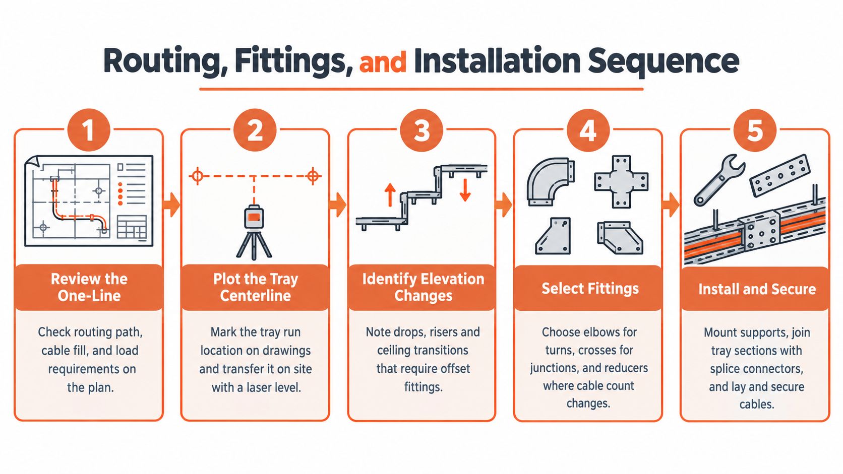
Build the route before ordering fittings
Pull the one-line and cable schedule into the plan review. Plot the tray centerline, transfer it to the field with a laser level, and mark every riser, drop, ceiling transition, wall penetration, and equipment entry. A route that looks straight on the plan can require several elevation offsets once it meets ductwork, process piping, doors, structural steel, and equipment maintenance clearances.
Select factory elbows, crosses, tees, reducers, and drop-outs where the manufacturer provides them. Factory fittings preserve the intended geometry and cable protection. Field-fabricated miters can work when permitted by the manufacturer and project specification, but the cut must be smooth, structurally sound, and compatible with the cable bend radius. Keep bends within the manufacturer's limits. A 30-degree bend rule, where specified by the system, helps keep pull tension and cable bending under control.
At wall and floor penetrations, coordinate the sleeve, tray opening, fire-rated assembly, and annular space. Products such as 3M FB-3000 WT and Hilti CFS-IS may be used only where their listed system covers the actual wall or floor construction, cable configuration, and opening condition. The listing controls the permitted annular space and installation method. Don't substitute a sealant because its name sounds similar.
For cable pulling, stage reels so the cable enters the tray without a sharp reverse bend. Place rollers at bends and along long straight runs, with project practice often calling for rollers at every 30 ft and at each bend. Match the pull rope and pulling method to the tray length, cable cross-section, and manufacturer's cable-handling requirements. Before energization, complete the splice-hardware torque check and confirm that cables are supported without crushed jackets or violated bend radii.
The cable management category from ATEK can help consolidate tray, fittings, connectors, and related support items for a coordinated material release. For dense rack environments, a practical reference on managing dense rack cables is useful when the tray route transitions into cabinets and overhead rack pathways.
The video below provides a visual installation reference.
A QA walk-down commonly finds missing bonding jumpers at expansion joints, unsupported reducers, sharp field-cut edges, unsealed penetrations, poor tray level, loose splice hardware, and covers left off where the specification required them. Resolve those items before the cable installation hides the work.
Quick Reference for Wire Cable Tray Selection
Use this field card before releasing a tray bill of material. The sequence is deliberate: classify the run, size the tray for its load, select the tray family, then document supports and bonding. That order keeps the cable schedule, route, and installation requirements aligned.
| Check | Field decision |
|---|---|
| Run classification | Identify power, control, communications, and fiber cables. Record the environment, required separation, bend radius, and allowance for future changes. |
| Load and span | Compare the calculated cable load with the selected product's working-load rating at the proposed support span. Confirm deflection limits from the submittal. |
| Tray family | Use mesh for accessible indoor routes, ladder for heavy feeder work, trough for many control cables, and solid bottom where protection or shielding outweighs reduced ventilation. |
| Dimensions and finish | Confirm width, depth, wire size, material, coating, fittings, and manufacturer's specified welded-grid pattern. |
| Supports | Show brackets, trapezes, reducers, vertical transitions, expansion locations, and structural attachment points on the layout. |
| Bonding and grounding | Identify listed splice hardware, jumper locations, bonding surfaces, grounding method, and whether the tray may serve as the EGC under the project rules. |
| Fill and working space | Calculate the applicable NEC fill requirement and preserve the required access around the route. |
| Standards check | Apply the NEMA class, tested span, installation requirements, and product documentation applicable to the selected system. |
NEMA classes A, B, and C, with their respective working-load values, are defined earlier in this guide. Use that table for the class comparison, then confirm the tested span, deflection, fittings, and finish for the exact product under consideration. Classification and installation guidance follow NEMA VE 1 and VE 2. The international benchmark is IEC 61537, which specifies requirements and tests for cable tray and cable ladder systems used to support cables and potentially other electrical equipment in electrical and communication installations.
Before procurement, verify that the proposed tray can carry the actual cable schedule at the specified span. A rating that works on a straight run may not cover concentrated loads, fittings, vertical sections, or changes in support spacing. Resolve those conditions in the design rather than relying on field adjustments.
If the cable schedule is incomplete, hold the release. Obtain the missing cable sizes, quantities, route information, environmental requirements, and grounding criteria, then select a product family with documented load, finish, fittings, and compliance data.
ATEK Distribution can review a tray bill of material, source wire mesh tray and support hardware, coordinate manufacturer documentation, and identify approved alternatives when availability changes. Visit ATEK Distribution for project-specific sourcing, submittal support, and procurement assistance for industrial electrical infrastructure.