
A technician is standing in front of a control panel with a failed relay, a replacement in hand, and eight terminals that look familiar enough to invite a guess. That guess is where many avoidable faults begin. An eight pin relay may use the same terminal count as a compact PCB relay, but the wiring logic, socket geometry, contact arrangement, and load limits can be very different.
For panel builders, maintenance teams, OEMs, and electrical contractors, the reliable approach is straightforward: identify the relay's physical format, verify the manufacturer's pin map, match the socket to the load, and derate contacts for the actual application. The octal eight pin relay remains useful because it combines a separated coil with two independent changeover contact sets in a replaceable plug-in assembly.
Table of Contents
- Understanding the Role of the Eight Pin Relay in Control Panels
- Internal Components and Basic Functionality
- Standard Octal Pinout Configurations
- Relay Base and Socket Selection
- Wiring Examples for Control Circuits
- Understanding Current Ratings and Derating
- Comparing Eight Pin Relays to Other Types
- Procurement and Sourcing Considerations
- Technical Reference and Quick Lookup Summary
Understanding the Role of the Eight Pin Relay in Control Panels
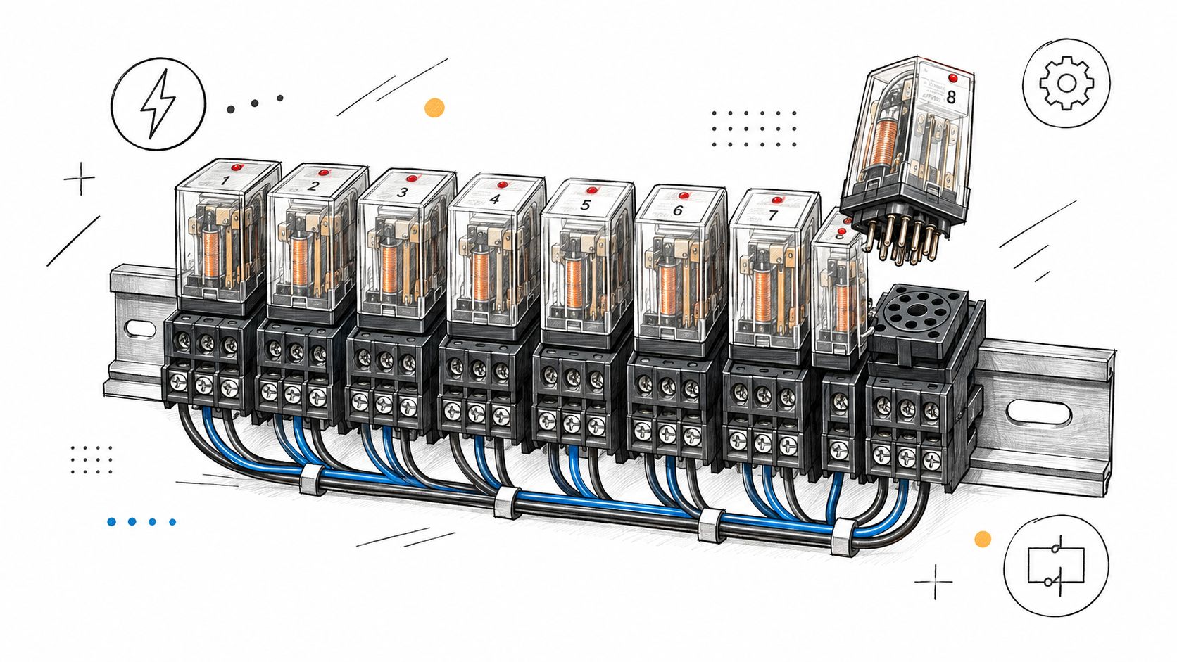
A replacement relay can fit the socket and still be wrong for the circuit. The octal eight pin relay is a panel component with a defined mechanical layout, not any relay with eight terminals. Its socket, retaining method, contact spacing, and wiring logic must match the relay body and the intended load.
In a typical control panel, the relay sits between a PLC or other low-power output and field wiring. The coil receives the control signal, while its contacts switch an interlock, alarm, valve command, or motor-control circuit. The common octal arrangement is a DPDT relay. One coil operates two electrically independent changeover poles, normally comprising two coil pins, two common pins, two normally open pins, and two normally closed pins.
That layout belongs to the plug-in octal family. Compact PCB relays may also expose eight terminals, yet place the coil and contacts in a different physical pattern and assign them according to a different wiring logic. A socket selected by terminal count alone can therefore put the wrong function on the wrong conductor. Confirm the manufacturer's pin map, relay outline, and socket keying before wiring. A breakdown of the octal relay architecture used in modular control systems provides a useful reference for this distinction.
Why the octal format remains practical
A socket keeps field conductors terminated while a technician replaces the relay. That reduces disturbance during fault-finding and makes spare replacement quicker, provided the base, clip, and relay are approved as a matching assembly.
The socket also exposes the mechanical limits that drawings can miss. Check terminal clamping, clearance, vibration resistance, and the relay's contact derating curve for the actual load. For wider panel and automation requirements, see ATEK's industrial control and automation offering. A sourcing partner can help verify the relay, socket, retaining clip, and protection accessory as one compatible family.
Internal Components and Basic Functionality
Inside an eight pin relay, the coil, magnetic circuit, armature, and contacts work as a mechanical switching system. The coil is an insulated winding around a magnetic core. When the correct control voltage is applied, current through that winding creates a magnetic field and pulls the armature toward the core.
The armature carries or operates the movable contacts. With the coil de-energized, each common terminal rests against its normally closed contact. When the coil energizes, the armature transfers the common connection to the normally open contact. The two contact poles operate from the same coil but remain electrically independent on the load side. Omega's relay reference identifies the eight pin octal relay as a DPDT device with separated coil and load contacts.
What the contact action means in practice
The labels describe the relay's state when the coil is off:
- COM is the moving contact connection.
- NC is connected to COM while the coil is de-energized.
- NO connects to COM after the coil energizes.
That operating sequence is useful for fail-safe signaling. A fault alarm can remain connected through NC until the relay energizes, while a pump permissive or valve command can be routed through NO. The correct choice depends on what the circuit must do during loss of control power.
Mechanical action and troubleshooting
A relay can fail electrically in its coil or mechanically in its contact system. A coil may be open, shorted, or receiving the wrong voltage. Contacts may become resistive, weld closed, or fail to transfer cleanly after repeated switching of a demanding load.
Listen for the armature movement, but don't treat an audible click as proof that the load contacts are healthy. Verify coil voltage at the relay terminals, then check continuity between COM and NC with the coil off and between COM and NO with the coil energized. Always isolate hazardous power and follow the equipment manufacturer's procedure before testing exposed terminals.
Field check: A relay that clicks but doesn't pass load current often has a contact, socket, or termination problem rather than a coil problem.
Standard Octal Pinout Configurations
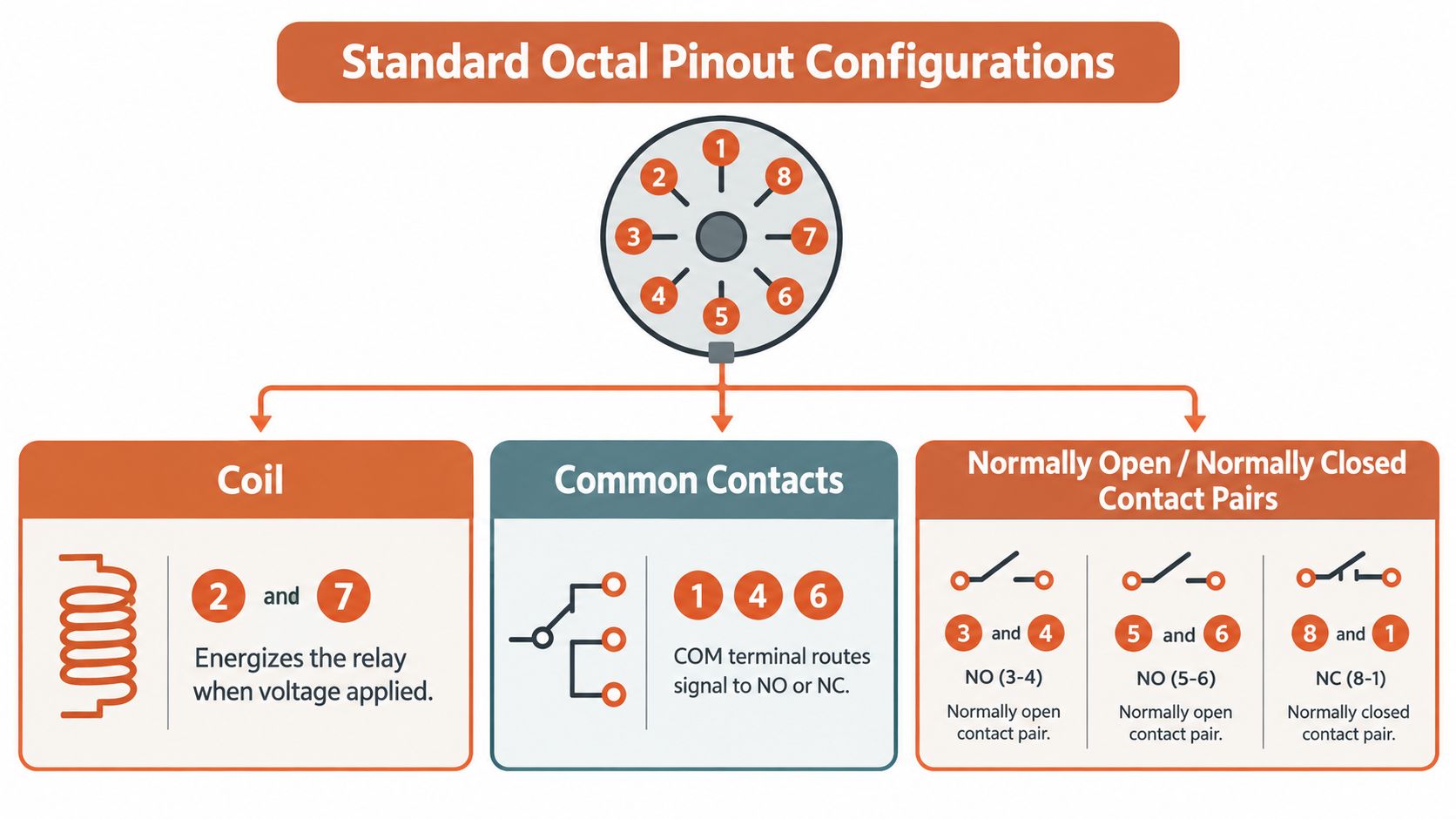
A relay can have eight terminals and still use the wrong wiring logic for an octal socket. In a standard octal layout, the coil commonly sits on pins 2 and 7, while the remaining terminals serve two changeover contacts. This standard octal wiring schematic shows pin 1 as one common, pin 4 as its NC contact, and pin 3 as its NO contact. The second pole uses pin 8 as common, pin 5 as NC, and pin 6 as NO.
Some industrial octal relays use a different contact numbering. In that arrangement, common terminals are pins 1 and 8, NC terminals are pins 3 and 6, and NO terminals are pins 4 and 5. A diagram of the alternate contact numbering used in some industrial octal relays illustrates this layout. Confirm the exact relay and socket diagram before wiring. Compact PCB relays may also have eight terminals, but their board footprint and terminal logic can differ from the round octal pattern.
A dependable identification sequence
-
Confirm the physical format. Check for the round plug-in body and matching octal socket. An eight-terminal square PCB relay may follow a different pin map.
-
Read the part documentation. Use the relay label, datasheet, socket markings, and panel drawing for the exact component family.
-
Locate the coil pair. Pins 2 and 7 are common in one standard octal arrangement. Verify them before applying control voltage.
-
Trace both poles. Identify each COM terminal and its matching NC and NO terminals. Mark conductors before replacing a failed relay.
-
Test both states. With power isolated, verify COM-to-NC continuity. Apply only the specified coil voltage for an energized test, then confirm transfer to NO.
-
Check viewing orientation. Relay underside numbering may appear reversed relative to markings beside the socket terminals.
The operating rule remains simple: coil off means COM touches NC, and coil on transfers COM to NO. Industrial relay-base guidance describes this relationship for plug-in relays used in control panels.
Relay Base and Socket Selection
The socket is part of the current path, not just a mounting accessory. A relay with suitable contact ratings can still produce a hot termination, unreliable connection, or damaged base if the socket is underspecified, poorly tightened, or mechanically unsuitable for the panel environment.
A compact PCB socket may be appropriate for a board assembly, but it isn't automatically a substitute for an industrial octal base. DIN-rail sockets typically provide a more serviceable installation, with screw terminals, relay retention, labeling space, and a replaceable plug-in interface. The mechanical choice should follow the panel layout, conductor size, vibration exposure, service requirements, and approved component family.

Compare the complete relay interface
| Selection point | PCB-style socket | Industrial octal socket |
|---|---|---|
| Mounting | Board-mounted | Plug-in panel or DIN-rail mounting |
| Wiring access | Usually through PCB traces | Dedicated screw or terminal connections |
| Service method | Board-level replacement | Relay replacement at the socket |
| Mechanical concern | Board fit and pin pattern | Keyway, retention, terminal access, and conductor security |
| Best fit | Compact electronic assemblies | Control panels and field-serviceable equipment |
Socket ratings may be independent of the relay rating. One industrial octal socket datasheet lists approvals including UL E59244 and CSA LR15734, with published configurations reaching 300 V and 15 A, or 600 V and 10 A, depending on the configuration. The socket datasheet provides the relevant approval and rating examples.
That doesn't mean every socket has those ratings. Confirm the exact base, terminal arrangement, voltage, current, conductor requirements, and mounting method. The lower-rated component governs the usable circuit.
A short demonstration can help technicians recognize the physical relationship between an octal relay and its base:
Installation rule: Match the relay, socket, retaining hardware, and any indicator or suppression module as a documented assembly. A relay that fits physically may still have the wrong pin logic or accessory compatibility.
Wiring Examples for Control Circuits
Start with the control side, not the load side. Confirm the coil voltage printed on the relay and compare it with the control circuit shown on the drawing. For a DC coil, observe polarity if the relay or its plug-in protection module includes a polarity-sensitive device. For an AC coil, follow the manufacturer's terminal instructions and the panel schematic.
A basic control sequence looks like this:
- Bring the control supply through the appropriate protective and switching devices.
- Connect the control return through the relay coil.
- Verify that the coil receives its specified voltage only when the command is active.
- Use one DPDT pole for the primary control signal and reserve the second pole for an interlock, status contact, or separate circuit when the application permits.
- Keep coil conductors and load conductors identified and segregated according to the panel design.
The contact wiring depends on the desired default state. A circuit that must remain complete while the relay is off uses COM and NC. A circuit that should become complete only after energization uses COM and NO. The second pole can switch another isolated circuit, but don't assume both poles may be used interchangeably without checking the relay's contact and insulation specifications.
Resistive and inductive loads
A resistive load is generally easier for a relay contact to interrupt because it doesn't produce the same stored-energy release as a coil or motor. Inductive loads, including contactor coils, solenoids, and motors, can generate arcing when the contacts open. Use the specified suppression method, such as an appropriately selected diode, RC network, or varistor, only where it's compatible with the circuit and approved by the design requirements.
A relay contact should not be treated as a motor starter because its nominal current appears adequate. Use a contactor, overload protection, or other purpose-built switching equipment where the application requires it. The eight pin relay can command that equipment rather than carry the motor circuit directly.
For secure field terminations, see ATEK's wire termination and supplies. The right ferrule, terminal accessory, conductor preparation, and labeling practice can prevent a good relay selection from being undermined at the connection point.
Understanding Current Ratings and Derating
Many general-purpose eight pin relays are cited at 10 A for 250 VAC or 10 A for 30 VDC on resistive loads. Relay rating and derating guidance explains that this figure applies to a specified resistive-load condition and shouldn't be carried directly into motor or solenoid service.
The contact rating is not a universal permission to switch every load at that current. Contact material, voltage, inrush, interruption frequency, load power factor, ambient temperature, enclosure heat, and suppression all affect service life. Inductive loads can sustain an arc as the contacts separate, which may pit or weld the contact surfaces.
What derating changes
Derating means applying a lower usable load limit than the headline resistive rating when the actual circuit is more demanding. A relay switching a contactor coil, pump motor, or solenoid should be evaluated against the manufacturer's load category and contact-life data, not just the steady-state current shown on a nameplate.
Look for these factors in the selection review:
- Load type: Resistive, inductive, motor, lamp, and electronic loads behave differently at make and break.
- Inrush current: A device may draw substantially more current during energization than during steady operation.
- Ambient temperature: Heat inside a crowded enclosure raises relay and socket stress.
- Switching frequency: Frequent operation increases mechanical and electrical wear.
- Suppression: Proper suppression can reduce contact arcing, but the device must suit the voltage and circuit type.
If the load is close to the nominal limit, select a larger switching device or use the relay to control a contactor. A fuse-selection reference from ATEK can also support the upstream protection review, but fuse protection doesn't replace correct relay derating or load classification.
Practical rule: Treat the published resistive rating as a starting point. The application decides the usable rating.
Comparing Eight Pin Relays to Other Types
An eight pin octal relay is a strong choice when the panel needs two changeover poles, a replaceable plug-in device, and a familiar round socket. It becomes less suitable when the design needs only one changeover pole, more than two poles, a compact PCB footprint, or a different terminal convention.
A five pin relay commonly serves a single changeover function with one coil and one contact pole. That can reduce wiring and physical size when a second independent circuit isn't required. The trade-off is obvious: it can't provide the same two-pole switching function as a DPDT eight pin relay.
A fourteen pin relay typically supports a higher contact count or a denser control function, depending on the product family. It may be the better fit when several isolated circuits must transfer from one command, but it also introduces a different base, terminal map, and panel footprint. An eleven pin device is another distinct format, often used where three changeover poles are required. Don't force a relay into a socket because the body appears similar. Pin geometry and numbering must match.
| Requirement | Practical direction |
|---|---|
| One changeover circuit | Consider a five pin format |
| Two independent changeover circuits | Consider an octal eight pin DPDT relay |
| More contact poles | Evaluate eleven or fourteen pin families |
| Board-level assembly | Use the matching PCB relay and socket pattern |
| Field-serviceable panel | Favor a documented plug-in base system |
The decision should follow the circuit count and installation method, not the terminal count alone. A compact relay with eight terminals may have a blade or PCB layout that has no relationship to the standard octal arrangement.
Procurement and Sourcing Considerations
Buying an eight pin relay by description alone creates avoidable risk. “Eight pin” identifies a terminal count, not a complete electrical specification. Procurement should capture the relay function, coil voltage and type, contact configuration, load category, contact material where specified, socket type, mounting method, approvals, and accessory requirements.
Use this verification sequence before releasing a purchase order:
- Match the part family: Confirm that the relay and socket share the same mechanical keying and terminal map.
- Check the load: Record whether the switched circuit is resistive, inductive, motor-related, or an interface to another control device.
- Review the socket: Verify current, voltage, terminal, mounting, retention, and approval information independently from the relay.
- Confirm documentation: Request datasheets, wiring diagrams, approval information, and product traceability where the project requires them.
- Plan alternatives: Pre-qualify an approved substitute before a shortage turns into a panel delay.
UL and CSA markings may apply to a socket, relay, or complete assembly in different ways. Don't treat a listing on one component as automatic approval for the entire installed combination. The project engineer, authority having jurisdiction, and manufacturer documentation determine what evidence the application requires.
ATEK Distribution can support BOM review, hard-to-source relay and socket identification, manufacturer coordination, approved alternative evaluation, and compliance documentation. That type of review is particularly useful when an obsolete relay must be replaced without changing the socket layout or when a control-panel build has a long-lead component.
Technical Reference and Quick Lookup Summary
The octal eight pin relay is easiest to manage when the electrical function and mechanical interface are recorded together. The coil pins, contact assignments, socket ratings, mounting arrangement, and load category all belong on the selection record.
| Reference item | Practical lookup |
|---|---|
| Common function | DPDT, with two independent changeover contact sets |
| Terminal count | Eight terminals |
| Coil arrangement in a common octal layout | Pins 2 and 7 |
| Common contact arrangement | Often pins 1 and 8, subject to the manufacturer's map |
| Typical general-purpose contact rating | 10 A at 250 VAC or 10 A at 30 VDC for resistive loads, when specified by the product |
| Socket rating | Independent of relay rating, with examples reaching 300 V, 15 A or 600 V, 10 A depending on configuration |
| Mounting options | Plug-in socket, panel mounting, or DIN-rail style industrial base |
| Default contact state | COM connects to NC with the coil off |
| Energized contact state | COM transfers to NO with the coil on |
Use the table as a starting point, not as a substitute for the exact datasheet. Published pin assignments vary, even among products described as octal or eight pin relays. Verify the relay face marking, socket diagram, and schematic before moving conductors.
For maintenance, record the relay part number and coil rating on the panel documentation. Mark the socket terminals clearly, test the de-energized and energized contact states, and inspect for heat discoloration, loose terminations, damaged retention hardware, or contact welding. If a relay fails repeatedly, investigate the load and suppression rather than treating replacement as the complete repair.
The most reliable selection combines four checks: correct pin logic, correctly rated socket, application-specific contact derating, and documented procurement traceability. That combination prevents the common mistake of selecting a relay that fits the hole but not the circuit.
ATEK Distribution helps contractors, engineers, facilities teams, OEMs, and procurement professionals source eight pin relays, matching sockets, protective devices, and related control-panel components. For BOM review, hard-to-source parts, approved alternatives, compliance documentation, or project-specific procurement support, visit ATEK Distribution.