
A crew finishes pulling tray cable wire through an industrial cable tray and routes it toward a motor starter. The cable is supported neatly, the terminations look clean, and the material matches the approved conductor size. At rough inspection, the installation still receives a correction because the cable leaves the tray and continues exposed to the equipment without the required exposed-run rating.
That failure rarely comes from bad workmanship. It usually starts earlier, when a purchasing description says “tray cable” without distinguishing standard Type TC from Type TC-ER. The difference affects routing, support, physical protection, environmental suitability, submittal approval, and the labor needed to complete the transition into equipment.
Table of Contents
- Why “Tray Cable” on a Purchase Order Isn't Enough
- Anatomy and Flame Performance of UL 1277 Cable
- Standard TC Versus TC-ER Exposed Run Ratings
- Navigating NEC Article 336 and Tray Fill Limits
- Matching Cable Construction to Industrial Environments
- Procurement Verification and Submittal Best Practices
- Sourcing Mission-Critical Electrical Infrastructure
Why “Tray Cable” on a Purchase Order Isn't Enough
A motor feeder can pass through an industrial tray correctly and still fail inspection at the equipment approach. The common mistake is ordering standard Type TC, then routing it from the tray to a motor, panel, or junction box as an exposed cable. Straps may be installed neatly, but the product marking may not permit that portion of the route. The inspector then treats the installation as an unapproved wiring method.
The correction costs more than conduit and fittings. A crew may need to return, install a short raceway, replace fittings, add supports, and reschedule inspection. On a congested project, that can consume a shift of electrician time and delay energization while the equipment and other trades wait for the revised connection.
Field rule: Never approve a tray cable purchase from the words “tray cable” alone. Confirm the exact listing and the complete route from the tray to the equipment.
Tray cable wire is a factory-assembled product class, not a generic name for any cable installed in a tray. NEC Article 336 defines Type TC as a factory assembly of two or more insulated conductors, with or without associated grounding conductors, under a nonmetallic jacket. The article addresses its installation and permitted uses, while UL 1277 governs the product standard. Review the NEC Article 336 definition and installation overview before accepting a substitution.
That construction distinguishes tray cable from individual building wire. Building wire can be suitable inside a raceway, but it does not automatically provide the factory assembly, jacket, flame performance, or listing required for a Type TC application. A Type TC listing also does not authorize every exposed transition, unsupported drop, or outdoor route.
Why the route matters more than the label
Trace the route physically. Mark the tray section, transition point, equipment approach, and each location where the cable becomes exposed. The rating must suit the complete path, not just the segment inside the tray. Put those points on the drawing and submittal so procurement, installation, and inspection use the same description.
The engineer identifies the wiring method, procurement verifies the cable marking, and the installer follows the approved route. If those descriptions differ, the inspector must resolve an ambiguity that should have been settled before delivery.
The practical distinction is direct. Standard TC belongs within the conditions allowed for Type TC. TC-ER is intended to support an exposed run when the applicable NEC conditions are satisfied. Neither designation removes the need for proper support, bend control, environmental protection, ampacity calculations, and AHJ acceptance. A small difference in the purchase description can therefore create a field correction, lost labor, and a delayed inspection.
Anatomy and Flame Performance of UL 1277 Cable
UL 1277 tray cable starts with multiple insulated conductors assembled under a nonmetallic jacket. The jacket protects the assembly from the mechanical and environmental stresses associated with cable trays, raceways, and supported outdoor locations. The conductors may be copper, aluminum, or copper-clad aluminum, depending on the listed construction and project specification, as described in the UL 1277 standard scope.
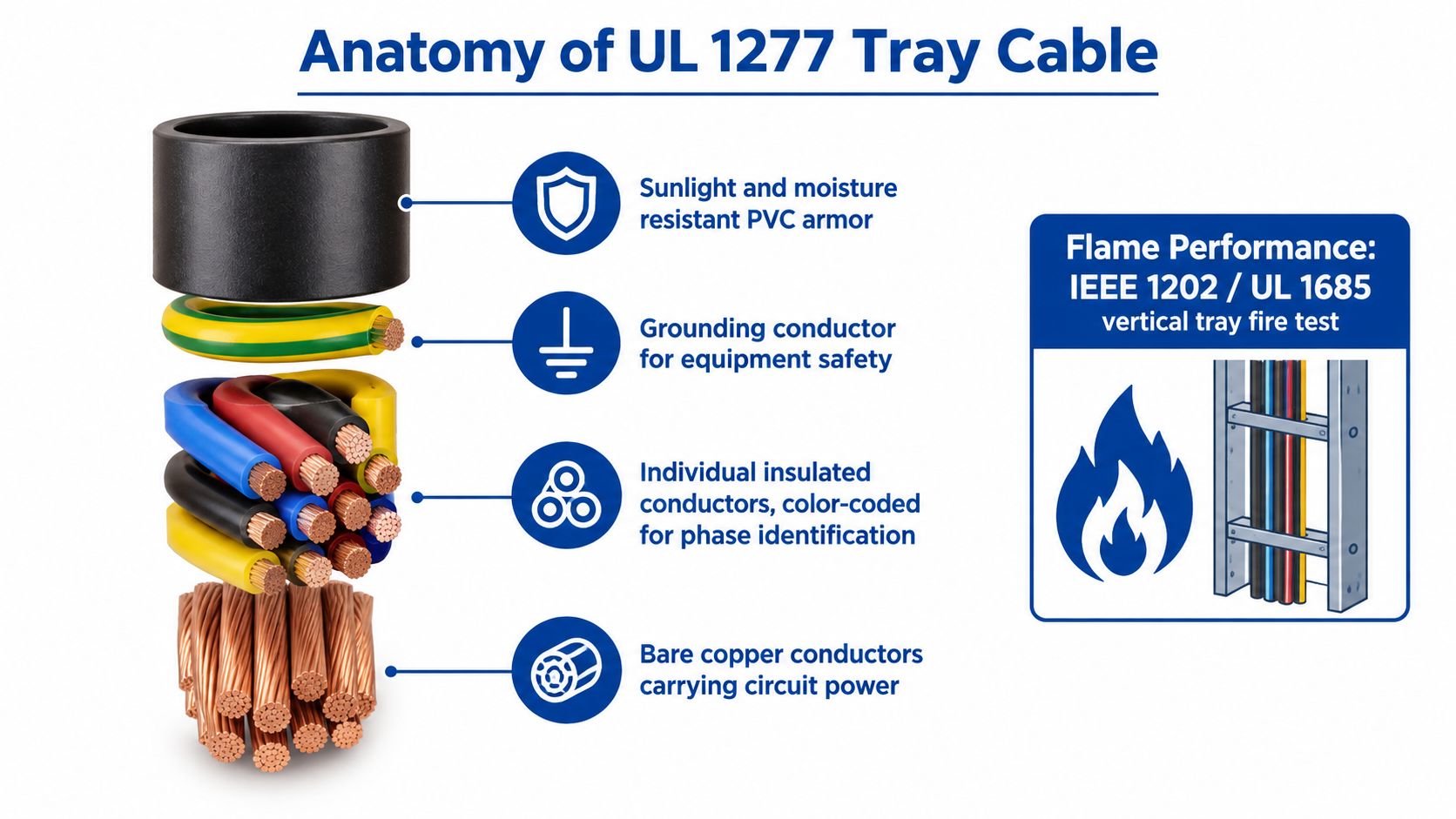
What the jacket and conductors do
The insulated conductors carry the circuit power or control signals. The grounding conductor, where included, provides the equipment grounding path specified by the design. Fillers and assembly components help create a stable, round cable profile, while the outer jacket holds the conductors together and provides the listed environmental and mechanical characteristics.
The minimum conductor size permitted under the UL 1277 definition is 18 AWG, according to published UL 1277 technical guidance. That minimum doesn't mean every small conductor is appropriate for every tray installation. Ampacity, terminal ratings, voltage drop, short-circuit withstand, control function, and the exact cable listing still govern selection.
Modern UL 1277 requirements also support dual-rated 600V/1kV tray cable. Manufacturers can qualify products for the higher voltage class when they use recognized 1 kV conductors and pass the required AC hipot test. A dual rating can simplify a project's approved-material schedule, but it shouldn't be treated as a universal replacement for a cable with a different environmental, flame, or exposed-run listing.
Why flame testing matters in a crowded tray
Cable trays often carry multiple circuits in close proximity. If a fault or external ignition exposes a cable assembly to sustained flame, a weak jacket can allow fire to travel along the pathway and affect neighboring circuits. UL 1277-listed tray cable must pass the UL 1685 vertical flame test, commonly referenced with IEEE 1202 and FT4 performance.
The test uses a 70,000 BTU/hr ribbon burner in a vertical chamber for 20 minutes, as summarized in technical guidance on identifying tray cables. Passing that test doesn't make a cable fireproof. It demonstrates that the construction has been evaluated for limiting flame propagation under a recognized tray-cable test method.
Use the listing as an engineering control, not as a substitute for installation discipline. Tray fill, spacing, support, separation, and the surrounding fire protection strategy still matter. A cable that passes the flame test can't compensate for an overloaded tray or an installation that ignores the manufacturer's instructions.
A product demonstration can help crews visualize the construction and handling requirements. Review the technical material before approving a substitute, and use the wire and cable product range when comparing available constructions.
Standard TC Versus TC-ER Exposed Run Ratings
The key question isn't whether both products can be installed in a cable tray. The question is what happens after the cable leaves the tray.
Standard Type TC is selected for permitted tray, raceway, or supported outdoor conditions. A TC-ER designation adds an exposed-run allowance between the tray and connected equipment, provided the installation satisfies the applicable Article 336 conditions. That can remove a short conduit transition, but it doesn't create permission to leave the cable unsupported or expose it to conditions outside the listing.
| Feature | Standard Type TC | Type TC-ER (Exposed Run) |
|---|---|---|
| Primary route | Cable tray, raceway, or permitted supported outdoor location | Cable tray plus permitted exposed run to equipment |
| Equipment approach | Usually requires a compliant raceway or other approved protection when leaving the tray | May allow the listed cable to continue exposed under the applicable conditions |
| Support | Must follow the cable and installation requirements | Must be secured and supported for the exposed segment |
| Physical damage | Requires protection where the route is vulnerable | The exposed allowance doesn't remove physical-damage limitations |
| Environmental exposure | Must match the product listing | Must match sunlight, moisture, temperature, chemical, and location requirements |
| Procurement check | Verify Type TC and voltage, conductor, jacket, and flame listings | Verify Type TC-ER marking plus all route-specific requirements |
Where TC-ER earns its place
TC-ER can make sense when a tray runs directly toward a motor, control enclosure, or other equipment and the final approach is visible, accessible, and adequately protected. Eliminating a short conduit section may reduce fittings, field measurements, threading or bending work, and installation steps. The benefit is strongest when the equipment layout is stable and the cable can be supported without sharp offsets or tight bends.
The labor advantage disappears when the route still needs conduit for physical protection. It also disappears when the product's sunlight or moisture resistance doesn't match the location, when the cable exceeds its bending limits, or when the crew has to add supports and corrections after inspection.
Practical distinction: TC-ER can simplify a transition. It cannot simplify an unclear design.
When standard TC is the safer choice
Use standard TC with a compliant raceway or protected transition when the cable passes through a location exposed to impact, abrasion, vehicle traffic, sharp edges, or difficult maintenance activity. A full conduit pathway may also be preferable where the AHJ expects a protected equipment approach or where the cable manufacturer's instructions limit exposed installation.
Procurement should put the route description beside the cable description. “Three-conductor tray cable” is incomplete. The purchase specification should identify the voltage class, conductor construction, jacket requirements, flame listing, environmental exposure, and whether the exposed-run segment requires TC-ER.
Navigating NEC Article 336 and Tray Fill Limits
A tray route can pass an initial design review and still fail at inspection when the cable listing, tray capacity, and exposed sections do not match. Article 336 addresses Type TC wiring methods and their permitted uses. Article 392 addresses the tray system. These requirements work together, but approval of the cable does not establish approval of the complete pathway.
Begin with the installed tray conditions. Calculate usable tray area from the cable outside diameters, circuit arrangement, tray type, support spacing, and manufacturer instructions. Check tray fill separately from ampacity adjustment. A cable arrangement can fit physically while requiring a different ampacity calculation, or satisfy ampacity requirements while exceeding the tray's usable capacity.
Keep the cable and the tray approvals separate
Three-or-more-conductor cables may be listed for exposed runs under the conditions in NEC Article 336.10(7), but that allowance depends on the actual cable listing and installation. Confirm the wording on the cable and project submittal rather than applying the allowance to every product described as tray cable.
The tray requires its own review under Article 392. Treat usable space as the manufacturer and design documents define it, not as the full nominal opening. Power, control, grounding, and mixed-voltage circuits may require different arrangements or separation. The cable's actual outside diameter also matters more than a generic product-family name.
A tray-specific field review should include:
- Measure actual cable outside diameter: Compare it with the tray's usable width and cross-sectional area rather than counting conductors.
- Check the fill calculation: Use the selected cable construction and the proposed circuit arrangement, including any planned additions.
- Review ampacity separately: Apply the adjustment requirements for the installed grouping and tray configuration.
- Verify support spacing: Confirm that the tray and any cable supports suit the cable weight, installation method, and manufacturer instructions.
- Confirm vertical sections: Check that drops and risers provide the support required by the cable construction and installation details.
- Document substitutions: Require design review before accepting a different jacket, outside diameter, conductor size, or listing.
Detail the tray-to-equipment connection
A tray calculation does not resolve the final connection. The transition drawing should show the cable's exit point, support method, bend radius, cabinet entry, and the point where additional physical protection begins. Those details affect labor as well as compliance. A standard TC cable may need conduit or other protection at the equipment approach, while a correctly listed TC-ER product may permit a more direct exposed connection where the installation conditions allow it.
The 18 AWG minimum conductor size associated with the UL 1277 definition describes product scope, not a design shortcut. A smaller conductor may fall outside the intended Type TC listing. A larger conductor can still create problems if its outside diameter exceeds the tray calculation or its terminations do not accept the selected construction.
Use cable management equipment and support products when configuring the tray pathway, and match each support method to the cable listing and approved details. The procurement package should show the tray calculation, cable identification, and transition requirements together, so an apparently minor substitution does not create hidden field labor or an inspection failure.
Matching Cable Construction to Industrial Environments
A cable that works inside a controlled manufacturing space may fail quickly on a rooftop or in a wastewater area. Voltage and conductor count are only the starting points. The jacket and insulation system must match sunlight, moisture, oil, chemicals, temperature cycling, movement, abrasion, and the physical access around the tray.
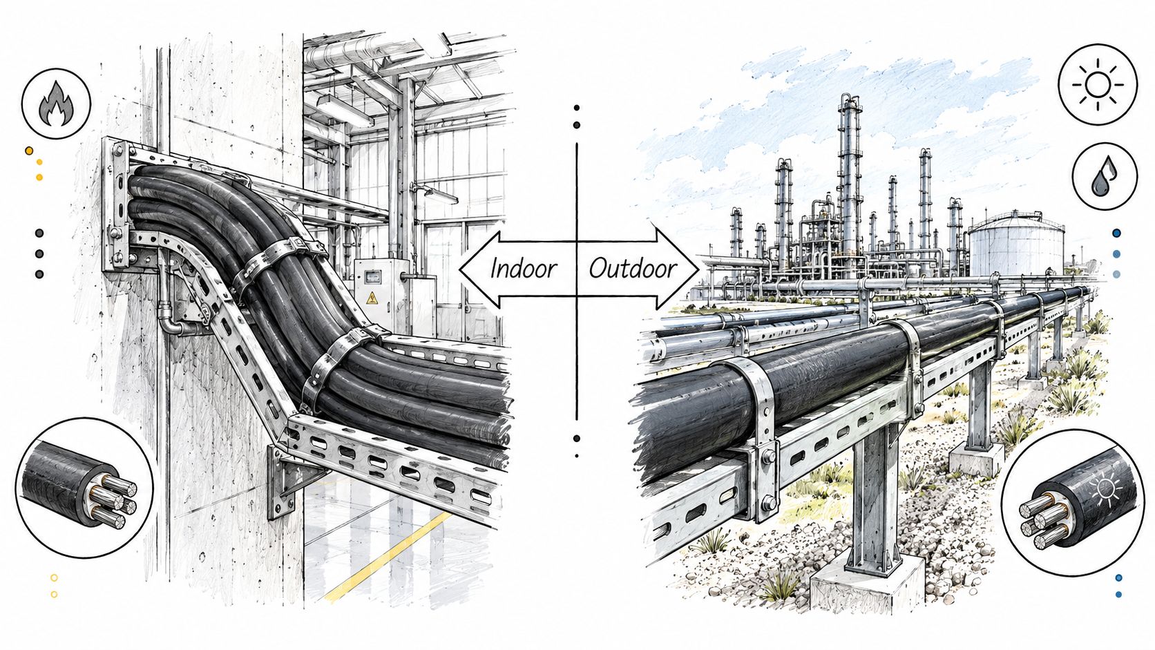
Match the environment before the catalog number
In a climate-controlled plant, the primary concerns may be cable routing, tray organization, ampacity, termination, and maintenance access. That doesn't eliminate the need to verify the jacket rating, but the environment may be less aggressive than an outdoor installation.
Rooftop solar arrays bring direct sunlight, temperature cycling, wind movement, and weather exposure. A tray cable selected for that route should carry the appropriate sunlight and moisture characteristics, and the supporting tray system must keep the cable from rubbing against sharp edges or moving under wind loads. A cable listed for an indoor dry location shouldn't be treated as an outdoor substitute.
Wastewater facilities can expose the jacket to persistent moisture, cleaning chemicals, corrosive atmospheres, and maintenance traffic. Petrochemical racks add another layer of concern, including oil exposure, heat, hazardous-location requirements, and the need to protect cable from impact during plant work.
A practical environment review asks:
- Sunlight: Is the jacket marked or documented for the intended outdoor exposure?
- Moisture: Is the wet-location performance appropriate for the route and drainage conditions?
- Chemicals and oil: Does the jacket resist the substances present at the facility?
- Temperature: Will the cable remain flexible and stable through the site's operating and installation temperatures?
- Physical stress: Could workers, vehicles, tools, vibration, or wind damage the exposed portion?
- Maintenance access: Can technicians reach the cable without creating repeated abrasion or unsupported movement?
Mixed tray and conduit paths need one continuous specification
A cable may pass through several environments on the same circuit. For example, a route can begin in an indoor tray, cross an outdoor rack, enter a conduit, and finish at a motor enclosure. The specification must address the most demanding section and any transition-specific requirements.
Standard TC and TC-ER decisions intersect with construction. An exposed-run rating may solve the routing issue, but it won't correct an unsuitable jacket compound or make a cable resistant to a chemical it wasn't designed to tolerate. Likewise, a sunlight-resistant cable still needs proper support and protection from physical damage.
Ask the manufacturer for the complete data sheet, not just a short catalog line. Confirm the listing, jacket material, wet and dry ratings, sunlight status, oil or chemical resistance, bending guidance, and approved installation methods before the submittal reaches the field.
Procurement Verification and Submittal Best Practices
The reel should be inspected before it reaches the installation crew. A correct purchase order can still result in a wrong shipment, a substituted construction, damaged jacket, or missing exposed-run designation. Receiving personnel need a verification process that compares the delivered cable with the approved submittal.
Verify the jacket marking first
Read the printing along the cable. Confirm the product type, voltage rating, conductor count, conductor size, grounding configuration, and any required TC-ER designation. The marking should support the exact route shown on the drawings. Don't rely on a distributor description that shortens the manufacturer's full marking.
Check the UL listing and product standard against the submitted cut sheet. If the project requires a dual-rated 600V/1kV product, the jacket and documentation should show that rating. If the project requires an exposed run, the marking must support that use rather than merely identify the product as generic Type TC.
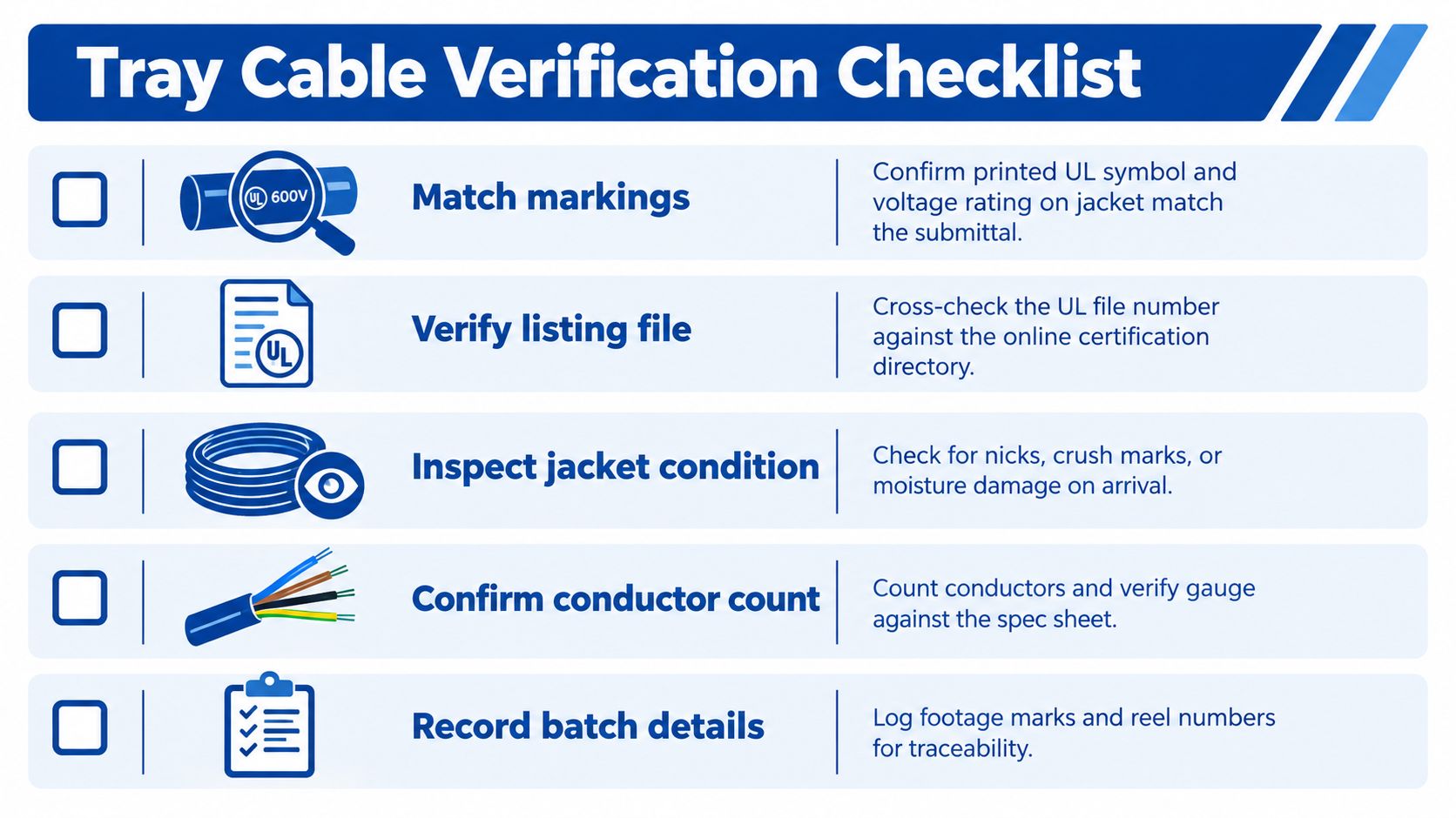
Use a receiving checklist that creates evidence
A short receiving inspection protects the project when a substitution or damage claim arises. Record the result against the reel or shipment, not only against the purchase order.
- Match the markings: Compare the printed jacket information with the approved submittal and equipment schedule.
- Verify the listing: Confirm the applicable UL 1277 listing and any required TC-ER designation in the manufacturer documentation.
- Inspect the jacket: Look for nicks, crushing, abrasion, flattened sections, moisture damage, and exposed conductors.
- Confirm conductors: Check the conductor count, gauge, insulation identification, grounding conductor, and shielding configuration where applicable.
- Record reel details: Capture footage marks, reel identification, manufacturer part number, and delivery documentation.
The UL certification directory can support listing verification when the project requires confirmation beyond the printed jacket. Use the manufacturer's current data sheet for construction and application details, then retain the approved version with the project records.
Control substitutions before they become field work
A substitute can look equivalent on voltage and conductor size while differing on jacket compound, wet rating, sunlight resistance, bend requirements, or exposed-run authorization. Require a written technical comparison before accepting an alternate. Government and institutional projects may also require Buy American Act or Trade Agreements Act documentation, so procurement should collect compliance records before shipment rather than during commissioning.
ATEK Distribution supports contractors sourcing electrical equipment with product sourcing, submittal documentation, alternate evaluations, and procurement coordination. Treat that support as part of the verification process, not as a replacement for the engineer's approval or the AHJ's interpretation.
Sourcing Mission-Critical Electrical Infrastructure
Cable selection and cable availability are connected, but they aren't the same decision. A project may need a particular conductor arrangement, jacket construction, voltage class, flame listing, and TC-ER designation, while the supplier offers only a visually similar product. Ordering the nearest catalog match creates risk if the marking or installation scope differs.
A specialized procurement partner can help the project team compare manufacturers, identify acceptable alternates, gather submittals, consolidate material, and coordinate delivery. That matters when the cable must arrive with the correct documentation and when a late substitution would force an engineering review or inspection correction.
The sourcing process should begin with the route, not the part number. Give the supplier the tray layout, exposed transitions, environmental conditions, conductor requirements, voltage class, termination details, and documentation requirements. Ask for a line-by-line comparison when the proposed product changes the Type TC or TC-ER designation.
ATEK Distribution supplies wire, cable, cable tray, fittings, and related infrastructure products, and provides sourcing, technical specification review, alternate product evaluation, compliance documentation, material consolidation, and expedited procurement support. For a mission-critical installation, that combination helps the project team keep the approved cable, the installation route, and the receiving records aligned.
Before ordering, send ATEK Distribution your tray route, conductor schedule, environmental requirements, and required TC or TC-ER designation for a technical sourcing review. Visit ATEK Distribution to request product options, submittal support, and coordinated procurement for tray cable wire and related cable-management infrastructure.